© 2017, IRJET | Impact Factor value: 5.181 | ISO 9001:2008 Certified Journal | Page 582
Taguchi method of optimization performed on 49 cm
2active area on
interdigitated flow channel of PEMFC
Dr V LAKSHMINARAYANAN
Department of Mechanical Engineering, B V Raju Institute of Technology, Narsapur, Telangana, India - 502313
---***---Abstract -
In this paper, optimization of operating anddesign parameters on interdigitated flow channel with 49 cm2 effective area of the Proton Exchange Membrane Fuel Cell (PEMFC) was considered numerically using CFD and Minitab 17 software. The factors considered for the optimization was landing to channel width ratios (L: C) -1:1, 1:2, 2:1 and 2:2, operating pressure (1, 1.5, 2 and 2.5 bar), temperature (313, 323, 333 and 343 K), anode and cathode reactants as stoichiometric ratios (S/F) of 3, 3.5, 4 and 4.5. Based on the optimization study, the
L:C-1:2
has maximum influence on PEMFC performance and square of response factor (R2) was achieved by Taguchi method as 99.9 %.Key Words: Interdigitated flow channel; CFD; Optimization; Design parameters; operating parameters.
1. INTRODUCTION
The Proton Exchange Membrane Fuel Cell (PEMFC) is an electrochemical device, which is converting chemical energy of fuels (hydrogen and oxygen) directly into electricity without any intermediate stage like classical combustion of two and four stroke engine. The PEMFC performance depends on the channel depth and width, flow channel design, number of flow path, cross section of the flow channel, operating pressure, temperature, relative humidity, mass flow rate of the reactant gases and stoichiometric ratio of the reactants. It is being developed for commercial applications in the field of transportation and back-up power. One of the main advantages of the fuel cells is the negligible emission of pollutants, such as SOx, NOx, particulates. It is Eco-friendly power source which is suitable for powering both portable devices and mobile application due to their high energy density and lower operating temperature range [1 & 2].The effect of the various parameters like landing width to channel width of (L: C) 1:1, 1:2 and 2:2 Multi pass serpentine flow channel PEMFC with 36 cm2 (6cm x 6cm) active area was analyzed numerically by Lakshminarayanan et al [3].The results revealed that the maximum power densities were obtained 0.658W/cm2 for the L: C of 1:1. Guvelioglu & Stenger [4] studied a CFD model to analyse the effects of channel size, electrode porosity and reactant humidification on the performance of PEMFC. The results revealed that smaller sized channels were required to obtain the higher current densities, although larger channels were satisfactory to produce moderate current densities. The effect of the relative humidity of the anode gas stream
was found to be the important factor for affecting the performance of the PEMFC.
Ahmed & Sung [5] investigated the performance of PEMFCs with different flow fields like a rectangular, trapezoidal and parallelogram using CFD. The results showed that a rectangular flow field gave higher cell voltages compared with parallelogram and trapezoidal flow fields. However, the trapezoidal flow field helped reactant diffusion, uniform reactant flow and current density circulations over the reacting area, results in lower cathode over potential of the fuel cell. The performance enhancement of the combined effect of design and operating parameters of both serpentine and interdigitated flow channel with 25 cm2 active area of PEM fuel cell with four different parameters using optimization technique and CFD carried out by Lakshminarayanan and Karthikeyan [6]. The results revealed that the peak power density of interdigitated flow channel with landing to channel width (L:C)1:2 showed better than the serpentine flow channel with L:C-1:2. Grujicic and Chittajallu [7] have studied the performance of PEMFC by using a single-phase two-dimensional electrochemical model. The model was coupled with a nonlinear constrained optimization algorithm to define an optimum design of the fuel cell with respect to the operation and the geometrical parameters of the cathode. The results of the optimization analysis showed that higher current densities at a constant cell voltage were obtained as the inlet air pressure. On the other hand, the statistical sensitivity analysis results showed that the equilibrium cathode/membrane potential difference has the largest effect on the predicted polarization curve of the PEMFC. Karthikeyan et al. [8] studied the performance of single channel PEMFC using Taguchi method for various operating and design parameters like cell temperature, back pressure, anode and cathode inlet velocities, porosity and thickness of the gas diffusion layer, cathode water mass fraction, flow channel dimensions, rib width and porous electrode thickness. The results revealed that the back pressure showed maximum effect and rib width had less effect on the PEMFC performance in the first stage. Further, enhancement of power density by 3% when selected factors in the second stage of fine-tuned optimization has been carried out.
© 2017, IRJET | Impact Factor value: 5.181 | ISO 9001:2008 Certified Journal | Page 583
performance. The results indicated that among the various parameters, temperature and pressure were the major factors to influence the PEMFC performance. The effects of interdigitated flow channel with traditional flow channel, the effects of the flow area ratio and the baffle-blocked position of the interdigitated flow field on the performance of PEMFC were examined experimentally by Yan et al [10]. The results concluded that, the cell performance can be enhanced with an increased inlet flow rate of reactant and cathode humidification temperature. The interdigitated flow fields have better performance than conventional flow field design. Also the results showed that the interdigitated flow field has larger limiting current density, and the power output was about 1.4 times than the conventional flow field. It is clearly indicated that immediate attention is required for optimizing the simultaneous influence of operating and design parameters for the performance of the PEMFC. Hence this paper has a detailed study about the optimization of operating parameters like operating pressure, temperature, stoichiometric ratio of inlet reactant mass flow rate and design parameter like various rib width to channel width (L:C)-1:1, 1:2, 2:1& 2:2 on interdigitated flow channel of 49 cm2 active area of PEMFC are to be studied and compared the influence of individual parameters contribution on the total performance of PEMFC.
2. MODEL DEVELOPMENT
[image:2.595.351.517.44.724.2]The modeling was done by creating all individual parts of the PEMFC and the dimensions of individual parts such as the anode and cathode GDL, solid polymer electrolyte membrane, the anode and cathode catalyst layers as shown in the Table 1. Three dimensional (3-D) PEMFC model with interdigitated flow channel of various landing width to channel width ratio (L: C) -1:1, 1:2, 2:1 and 2:2 was created by Creo Parametric 2.0 and meshed by using ICEM 14.5 (a module of Ansys 14.5) as shown in Fig.1.
Table -1: Dimensions and Zone type of parts assigning of fuel cell
(a)
(b)
(c)
(d)
Fig -1: Various landing to channel width (L: C) (a) 1:1 (b) 1:2 (c) 2:1 and (d) 2:2 of interdigitated flow channel of 49
cm2 active area of PEMFC S.
No Part Name
Wid th
(mm )
Len gth
(mm )
Thickn ess (mm)
Zone type
1 Anode & Cathode Flow channel
70 70
10 Solid
2 Anode & Cathode catalyst 0.08 Fluid
3 Membrane 0.127 Fluid
© 2017, IRJET | Impact Factor value: 5.181 | ISO 9001:2008 Certified Journal | Page 584
After geometry modeling, the next step was discretization of PEMFC done by ICEM software. The Cartesian grid meshing method was used, which is used in the formation of hexahedral mesh to attain accurate results. Split block method was used for blocking and body fitted mesh was used for meshing. The projection factor was set to 1and the projection factor decides how closely the edges of the mesh match up with the grid.
The simulation of PEMFC was solved by simultaneous equations like conservation of mass, momentum, energy, species concentration, butler–Volmer equation, Joule heating reaction and the Nernst equation to obtain reaction kinetics. The model used to consider the system as 3-D, steady state and inlet gases as ideal condition, system as an isothermal and flow as laminar, fluid as incompressible, thermo physical properties as constant and the porous GDL, two catalyst layers and the membrane as an isotropic.
A control volume approach based on commercial solver FLUENT 14.5 was used to solve the various governing equations. Three-dimensional, double precision and serial processing were used for this model. The species concentration on anode side of H2, O2, and H2O were set to 0.8, 0, and 0.2 respectively. Similarly, on the cathode side were set as 0, 0.2 and 0.1 respectively. The porosity at anode and cathode side was 0.5. Open circuit voltage was set at 0.95 V on the cathode and the anode was grounded. The cathode voltage has been varied from 0.05 V to 0.95 V used for solving kinetics reaction in order to get the current flux density H2, O2, and H2O fractions along with the flow field design. Multigrid settings were modified as F-Cycle for all the equations and entered termination restriction value was set as 0.001 for H2, O2, H2O and water saturation. The Anode and Cathode reference current density was set to be 10000 A/cm2 and 20 A/cm2 respectively 0.1 kmol/m3 was set to anode and cathode reference concentration, Anode and cathode exchange coefficient was set to be 2. The Reference diffusivity of H2, O2 and H2O was set to as 3E-5. The electric and proton potential values were set at 0.0001. Stabilization method BCGSTAB was selected for H2, O2, H2O, water saturation, electric and proton potential.
Taguchi method of optimization has been used to find out the most optimum combination among the various input parameters which would result in getting the maximum possible output which causes the performance enhancement of PEMFC. The factors considered for the analysis were rib to channel ratios on interdigitated flow field design (L: C-1:1, 1:2, 2:1 and 2:2), pressure (1, 1.5, 2 and 2.5 bar), temperature (313, 323, 333 and 343 K), anode and cathode reactants as stoichiometric ratios (S/F) of 3, 3.5, 4 and 4.5. The standard L16 orthogonal array with 4-level and 4 factors was used and the parameters were considered as low, high and medium range values. When this orthogonal array was used, significance of factors and optimum combination can be found in 16 runs itself. The theoretical value of hydrogen in the anode side was 4.33E-07 kg/s and oxygen in the cathode side was 3.33E-06 kg/s.
3. RESULTS AND DISCUSSION
As per L16 orthogonal array, the inputs of 16 combination of various parameters were given to the Ansys CFD Fluent analysis software and having all other parameters constant. The obtained power densities from analysis software for all 16 runs were fed in to the Minitab 17 software. The corresponding Signal/Noise (S/N) ratios for all 16 combinations were found from Minitab 17 software itself as shown in the Table 2.
[image:3.595.332.558.423.733.2]The landing to channel width ratio of 1:1 for interdigitated flow field has shown maximum power densities of 0.195 W/cm2 and minimum power densities of 0.142 W/cm2respectively. Similarly for L:C of 1:2 and 2:1 having maximum power density of 0.203W/cm2 and 0.161 W/cm2 respectively. The minimum power densities for the same L:C ratios have 0.157W/cm2 and 0.127 W/cm2 respectively. For the landing to channel width ratio of 2:2 has shown maximum power density of 0.189 W/cm2 and power density of 0.159 W/cm2. The optimization was performed for “Larger the Better” type of Taguchi method since power output of PEMFC must be maximized. The S/N ratio plot for the same were obtained using Minitab 17 software and the corresponding maximum S/N ratio gives better performance as analyzed based on larger the better as shown in the Fig.2.
Table -2: Factors, levels, power density and S/N ratio for 16 runs of optimization
Ru
n R:C
Pr ess ure
Tempe rature
Stoi. Rati o
Power Density
(W/cm2) S/N Ratio
1
1x 1
1 313 3 0.141 -16.9838
2 1.5 323 3.5 0.159 -15.9262
3 2 333 4 0.179 -14.9638
4 2.5 343 4.5 0.195 -14.1839
5
1x 2
1 323 4 0.169 -15.4043
6 1.5 313 4.5 0.157 -16.0978
7 2 343 3 0.203 -13.8341
8 2.5 333 3.5 0.197 -14.1025
9
2x 1
1 333 4.5 0.144 -16.8392
10 1.5 343 4 0.161 -15.8525
11 2 313 3.5 0.127 -17.8901
12 2.5 323 3 0.143 -16.8818
13
2x 2
1 343 3.5 0.189 -14.4271
14 1.5 333 3 0.187 -14.5604
15 2 323 4.5 0.175 -15.1536
16 2.5 313 4 0.159 -15.9489
© 2017, IRJET | Impact Factor value: 5.181 | ISO 9001:2008 Certified Journal | Page 585
Fig.2. Mean S/N ratio plot for Pressure (U1-U4),Temperature (V1-V4), L:C (X1-X4), Stoi.Ratio (Y1-Y4)
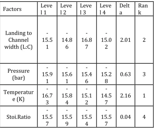
[image:4.595.35.286.99.261.2]Based on the result available from the Table 3, It was concluded that the design parameter such as, landing to channel width ratio of interdigitated flow channel having -1:2 as X2, and the operating parameters like pressure - 2.5 bar as U4, temperature - 343 K as V4, Stoichiometric ratio of inlet mass flow rate - 4 as Y3 were the optimum parameters to show the better PEMFC performance. The optimization results of various parameters were based on S/N ratios and the significance of each factor by ranking them according to their performance. Delta value of each factor available on the Minitab 17 software itself was shown in Table 3.
Table 3. Mean S/N ratios, Delta and Rank for each level of factors
Factors Level 1 Level 2 Level 3 Level 4 Delta Rank
Landing to Channel width (L:C)
-15.5
1 -14.8
6 -16.8
7 -15.0
2 2.01 2
Pressure (bar)
-15.9
1 -15.6
1 -15.4
6 -15.2
8 0.63 3
Temperatur e (K)
-16.7
3 -15.8
4 -15.1
2 -14.5
7 2.16 1
Stoi.Ratio 15.5 -7
-15.5
9 -15.5
4 -15.5
7 0.04 4
The factor with highest delta value indicates higher significance factor. It was found that the operating pressure was the predominant factor affecting the performance and it has been contributed as 45.24 % of overall performance of PEMFC. The other parameters were also influencing the performance to a considerable extent such as, landing to
[image:4.595.304.566.250.522.2]channel width ratio (L:C) of interdigitated flow channel was to be 19.02%, stoichiometric ratio of inlet mass flow rate was 10.54% and operating temperature was to be 0.97% respectively. The combined effect of combination of pressure with temperature and pressure with L:C has shown 0.11 % and 16.95 % respectively contributing to peak power performance of the PEMFC. Also the percentage contribution of individual parameters, P-test and F-test on the interdigitated flow fields for the performance of PEMFC has been shown in the Table 4.
Table 4.The percentage contribution of individual parameters of interdigitated flow channel
Factors DO F
Sum of square
s
Varian
ce F-test
P-Tes
t
Contri bution
(%) Pressure 2 0.000364 0.00018 910.08 0.076 45.24 Tempera
ture 2 0.000808 0.00040 2020.96 0.018 0.97 Stoichio
metric ratio
2 0.0000
14 0.00001 35.55 0.11 10.54
L:C 3 0.003189 0.00106 2659.64 0 19.02 Pressure
& Tempera
ture
1 0.0000
23 0.00002 58.26 0.017 0.11
Pressure
& L:C 3 0.000008 0 6.28 0.14 16.95
Error 2 0.000001 0 7.17
Total 15 0.007708 0.001682167 5684.63 0.361 100
4. CONCLUSIONS
The maximum power density for optimizing the four different parameters on 49 cm2 active area of interdigitated flow channel of PEMFC using CFD Fluent software was found to be 0.203 W/cm2 from L:C-1:2 with 2 bar operating pressure, 343 K temperature and 3 stoichiometric ratio of inlet reactant gases and R2 value was arrived 99.9 %. The maximum to minimum percentage of power deviation in 49 cm2 interdigitated flow channel has found to be 59.8. The performance of PEMFC with various design and operating parameters has been affected considerably.
REFERENCES
[1] Nicholas, S.;Siefert.; Shawn Litster.(2011).Voltage loss
[image:4.595.31.295.466.685.2]© 2017, IRJET | Impact Factor value: 5.181 | ISO 9001:2008 Certified Journal | Page 586
[2] Manso, A. P.;Garikano, X.;GarmendiaMujika, M.(2012).Influence of geometric parameters of the flow fields on the performance of a PEM fuel cell, A review International Journal of Hydrogen Energy, 37,15256-15287.
[3] Lakshminarayanan V, Karthikeyan P, Kiran Kumar DS
and Dhilip Kumar SM K. Numerical analysis on 36cm2 PEM fuel cell for performance enhancement, ARPN Journal of Engineering and Applied Sciences, 2016, 11, no. 2.
[4] Guvelioglu, GH & Stenger, HG 2005, 'Computational
fluid dynamics modeling of polymer electrolyte membrane fuel cells', Journal of Power Sources, vol. 147, no. 1, pp. 95-106.
[5] Ahmed, DH & Sung, HJ 2006, 'Effects of channel
geometrical configuration and shoulder width on PEMFC performance at high current density', Journal of Power Sources, vol. 162, no. 1, pp. 327-339.
[6] Lakshminarayanan V & Karthikeyan P. Optimization of
Flow Channel Design and Operating Parameters on Proton Exchange Membrane Fuel Cell Using Mat lab. Periodica Polytechnica Chemical Engineering. Budapest Univ Technology Economics. 2016, 60, 3; 173-180.
[7] Grujicic, M & Chittajallu, K 2004, 'Design and
optimization of polymer electrolyte membrane (PEM) fuel cells', Applied surface science, vol. 227, no. 1, pp. 56-72.
[8] Karthikeyan, P, Muthukumar, M, Shanmugam, SV,
Kumar, PP, Murali, S & Kumar, AS 2013, 'Optimization of Operating and Design Parameters on Proton Exchange Membrane Fuel Cell by using Taguchi method', Procedia Engineering, vol. 64, pp. 409-418.
[9] Wu, S-J, Shiah, S-W & Yu, W-L 2009, 'Parametric analysis
of proton exchange membrane fuel cell performance by using the Taguchi method and a neural network', Renewable Energy, vol. 34, no. 1, pp. 135-144.
[10] Yan WM, Chen CY, Mei SC, Soong CY & Chen F. 'Effects