© 2017, IRJET | Impact Factor value: 6.171 | ISO 9001:2008 Certified Journal | Page 1951
Design and Analysis of Fixture for component Body in HMC-800
Sanket
1, Ambadas
2, Babu Reddy
31
M.Tech Student, Dept. of Machine Design VTU PG centre kalaburagi -585105, Karnataka, India
2Assistant Professor & Course coordinator, Dept. of Machine Design VTU PG centre kalaburagi -585105,
Karnataka, India
3
Assistant Professor, Dept. of Machine Design VTU PG centre kalaburagi -585105, Karnataka, India
---***---Abstract - Fixture is a work holding device used for holding,
supporting and guiding the workpiece for performing different machining operations. Aim here is to design and analyze the special fixture used to hold, support and guide the component body which is used in defence application. Fixture modeling of each component and its assembly is done in software called solidworks and FE analysis is conducted using ANSYS and correlation studies were carried out.
Key Words: Horizontal Machining Centre-800, Solid
works, Cutting force, Fixture assembly & Ansys Software.
1. INTRODUCTION
Fixture is a holding device for fixing, supporting and positioning the work piece for specific operations. It only provides a reference surface or device. The word “Fixture” is derived from latin word which means fixed or attached. Jig is a work holding device that holds, supports and locates the workpiece and guides the cutting tool for a specific operation. Fixture does not provide any help to guide the tool as that of jig. But it is always fixed in a particular position on the machine. Fixtures are normally designed in order to perform definite operation.
The main purpose of the fixture is to provide a safe mounting point allowing support during process and to provide improved accuracy, reliability and inter changeability in the finished part. It also allows you to quickly set up and smooth the transition from parts to it to reduce working hours. It often reduces the complexity of the process, allowing unskilled workers to perform this process and effectively transfer the skills of toolmakers to unskilled workers.
Machining is essentially a method of removing material or stock to a specified limit or tolerance. In order to control this removal rate, the tool is equipped with a stops and gauges. Many machining operations can be done by clamping the work directly onto the surface of the machine without the use of a fixture, requiring only a few parts to be machined. But the number of parts is large enough to prove the cost of the fixture, usually used for holding and positioning. if fixture is not used during operation the machine may require two or more operators, and when fixture is used it eliminate one of the operators.
1.1 Purpose Of Fixture
The main purpose of the fixture is to locate the workpiece quickly and accurately, Support it properly and hold it securely, thereby ensuring that all parts produced in the fixture will come out like within the specified limits. In this way accuracy and inter-changeability of the parts are provided. By maintaining or even improving the inter changeability of the parts, a fixture contributes to a considerable reduction in the cost of assembly, maintenance and the subsequent the potential of standard machines and the quality of the parts are produced. One important goal, to design a fixture in such a way as to make it foolproof, and there by contribute to added safety for the operator as well as for the machine tools and other parts being used.
1.2 Classification of fixtures
Fixtures are classified according to following factors.
Application Based
1. Work holding fixtures 2. Tool holding fixtures 3. Fit- up fixtures 4. Gauging fixtures 5. Holding fixtures
Based On Degree of Mechanization and Automation
1. Hand operated 2. Power operated 3. Semi-automatic 4. Automatic
Based On Operation
© 2017, IRJET | Impact Factor value: 6.171 | ISO 9001:2008 Certified Journal | Page 1952
1.3 Fixture Materials
Fixtures are made from variety of materials, some of which can be hardened to resist wear. Sometimes it is necessary to use non-ferrous metals such as phosphor bronze to reduce the wear of components or nylon or fibres to prevent damage to the workpiece.
The materials used in fixture are –
1. High-speed steel: Mainly used for cutting tools, such as drill bits, reamers and Cutting cutter. These can be oil or hardened to 64 to 66 Rc.18% tungsten and 22% tungsten HSS also contains 4.3% chromium 1.6% vanadium and less carbon, molybdenum and so on.
2. Die steel: These are mainly used for hot working or cold working moulds, die steel for stamping tools that can be hardened to 65RC, which contains about 1% carbon, 0.5 to 1.5% tungsten and a small amount of silicon, hardening. Mold steel for extrusion, forging and die casting mold, due to hot processing and subject to high temperature. These are usually oil/air hardened to 40 to 50 RC, containing 2-5% chromium, 4-9% tungsten, 0.4-0.5% vanadium and a smaller amount of manganese and silicon.
3. Carbon steel: These can be used for standard cutting tools. They contain 0.85% carbon, 0.5-0.8% manganese and a smaller amount of silicon. These can be hydrated to 62 to 63% of the RC. The steel can be used for drill bushings, locators and other parts that are worn and require hardening.
4. Collet steel: These springs steel contains 1% carbon, 0.5% manganese and a small amount of silicon, chuck steel can be oil / water hardened to 47 RC.
5. Non Shrinking tool steels: This is also known as high carbon (1-2%) or high chromium (4-12%) steel. These steels are distorted during heat treatment and are easy to handle when they are not possible to eliminate heat treatment distortion. Oil is hardened to 60-64 RC. These steels are widely used in fine, complex pressure tools.
1.4 Objective
The objectives of this project are –
a. Design a fixture for component Body.
b. Fixture is designed such that it is suitable only for Horizontal milling machine.
c. The fixture has to be designed for holding and guiding the component body while performing drilling, milling and tapping operations.
d. The Analytical calculation of fixture is validated with FE analysis.
2. LITERATURE REVIEW
N. P. Maniar and D. P. Vakharia, HMC is best solution for particular component but designer can’t ask industries to replace CNC with HMC because of the cost factor, as HMC cost more than CNC. With the help of creo element/ proe5.0 the unbalance mass and its location of C.G are found out and it is remarkably same as experimental result on dynamic balancing machine. So, Computer aided mass balancing of quadrants is found more accurate to decrease in percentage error by almost 6%. [1]
Vaibhav S Warule and Suresh M sawant proposed a computer aided fixture design technique avail the model of designed fixture to the designer before getting manufactured and can show deficiency so that designer can make modification without getting it to manufacture. This saves lot of time and money. Fixture is designed for heavy component to perform milling operations using pegard horizontal boring machine and static workbench analysis is carried out using Ansys. The results obtained are CAFD greatly reduces the time for designing fixture which is hard to design manually. [2]
Iain Boyle et al. To achieve the current market requirement manufacturers need to ensure that their manufacturing practices are sufficiently flexible to allow them to achieve rapid product development. In order to enable flexible fixturing, considerable levels of research effort have been devoted to supporting the process of fixture design through the development of computer-aided fixture design (CAFD) tools and approaches. Over seventy-five CAFD tools and approaches are reviewed in terms of the fixture design phases they support and the underlying technology upon which they are based. [3]
Li B has given a method of solving the clamping force optimization is given in which the positioner is considered to be deformable and the workpiece is rigid. It is found that the optimum clamping force can reduce the position error due to the application of the machining force. [4]
3. DETAILS OF FIXTURE FOR COMPONENT BODY
© 2017, IRJET | Impact Factor value: 6.171 | ISO 9001:2008 Certified Journal | Page 1953 Figure 1: Isometric view of Component Body
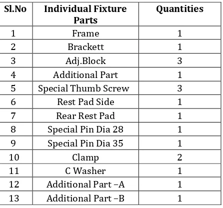
Table 1: Individual parts list with quantities
3.1 Analytical Calculation And Fe Analysis
Cutting force calculation for drilling operation:
In this drilling operation the cutting force has been calculated using the specifications which are given below.
Component name Body Component Material Aluminium Cutting Speed 50
[image:3.595.32.255.426.634.2]Depth Of Cut 3mm Feed Per Revolutions 0.2 Mm Cutter Diameter Ø25mm
Table 2: Specification for Drilling operation
Revolution / minute (rpm)
V = π D n /1000 m/min n = (V x 1000)/ (π D) = (50 x 1000)/( π x 25) n = 636.61
Power at the Spindle (Kw)
N = 1.25 x D2 x k x n (0.056 + 1.5 x s)/ 105
= {1.25 x (25) 2 x 0.55x636.61 x (0.056+1.5x 0.2) }/ 105 N = 0.97381
Power at the motor (Kw)
Nel = N /E
= 0.97381/0.8 Nel = 1.217
Torque at the Spindle (N-m)
Ts = 975 x N / n
= (975 x 0.97381) / 636.61 Ts = 14.63
Cutting Force (N)
Tf = 1.161 x K x D (100 x s) 0.85 = 1.161 x 0.55 x25(100 x0.2)0.85 Tf = 1999.6
The cutting force for drilling operation is 1999.6N
Analytical Calculation For Bolt And Brackett
Bolt and Brackett are two critical parts in fixture, because of that stress and deformation has been calculated for forces calculated under operating condition.
For Bolt ,
Force F=2000N Sl.No Individual Fixture
Parts Quantities
1 Frame 1
2 Brackett 1
3 Adj.Block 3
4 Additional Part 1 5 Special Thumb Screw 3 6 Rest Pad Side 1 7 Rear Rest Pad 1 8 Special Pin Dia 28 1 9 Special Pin Dia 35 1
10 Clamp 2
11 C Washer 1
© 2017, IRJET | Impact Factor value: 6.171 | ISO 9001:2008 Certified Journal | Page 1954 Diameter(mm) Area(mm2)
d1= 40mm A1= (πd2)/4 = (π× (40)2)/4 A1 = 1256.6 d2=12mm
A
2=(π×(12)
2)/4
A
2=113.09
d3=9mm
A
3= (π ×(9)
2)/4
[image:4.595.42.551.46.778.2]A
3= 63.61
Table 3: Calculation of Area
Stress =Force/Area = F/A
=2000[(1/A1)+(1/A2)+(1/A3)]
=2000[(1/1256.6)+(1/113.09)+(1/63.61)] = 50.71N/mm2
Deformation = (FL) /(AE)
=F/E[(L1/A1)+(L2/A2)+(L3/A3)] = (2000/2×105)[(14/1256.6) +(52/113.09)+(7/63.61)] = 5.8× 10⁻³mm
For Brackett,
Moment of inertia (mm4)
I = bh3/12 = 134 (40)3/12 I = 714.6 103
Bending Moment (N-mm) M = Force distance = 2000 88
M =176000
Stress (MPa) =(M/I)
=(176000/714.6 103) 20 = 4.92
Deformation (mm)
= (FL3) /(3EI)=(2000(134)3)/(3x2x105 714.6 103) =0.00112
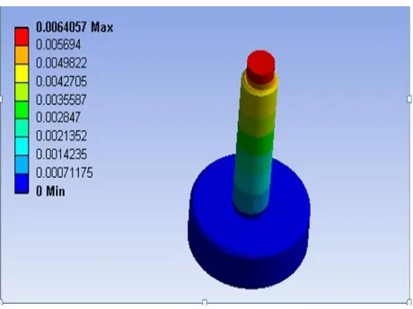
3.2 Static Analysis of Bolt
Bolt has been designed in solid works and it has imported to ansys for analyzing , . Bolt head has been fixed and load of
[image:4.595.321.547.146.325.2]2000N has applied at extreme end of bolt head. Boundary condition and applied load location in the bolt is shown in figure
Figure 2: Boundary condition and load
Figure 3: Deformation Plot of Bolt
[image:4.595.319.549.357.529.2]© 2017, IRJET | Impact Factor value: 6.171 | ISO 9001:2008 Certified Journal | Page 1955 Figure 5: von-Mises Stress plot
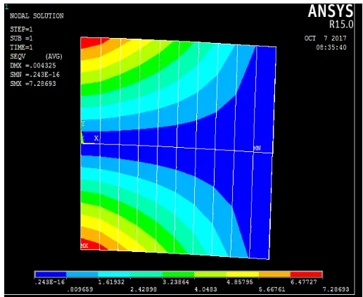
3.3 Static Analysis of Brackett
[image:5.595.39.286.91.263.2]Brackett has been designed in solid works and it has imported to ansys for analyzing. Transverse load is coming on bracket so it solved by considering as cantilever beam. One end of bracket is fixed and transverse load of 2000N had applied at other end of bracket. Boundary condition and applied load is shown in figure 5.
[image:5.595.304.570.104.280.2]Figure 6: Load and Boundary condition
[image:5.595.305.563.317.528.2]Figure 7: Deformation plot of bracket
Figure 8: Stress plot of Brackett
Figure 9: von-Mises Stress plot
3.4 RESULT AND DISCUSSION
Critical
parts Analytical Results FE Results Bolt = 50.71MPa = 55.64 MPa
=5.8× 10⁻³mm =6.4× 10⁻³mm
Brackett = 4.92 MPa = 3.13 MPa =0.0011mm =0.00196mm
[image:5.595.36.287.402.524.2] [image:5.595.35.284.558.724.2]© 2017, IRJET | Impact Factor value: 6.171 | ISO 9001:2008 Certified Journal | Page 1956 Analytical and FE Result comparison for Bolt element.
Displacement value obtained in analytical method and FE are 0.0058mm and 0.0064mm respectively, An analytical stress value in bolts is 50.71MPa and numerical value of stress is 55.64 MPa which are shown in table 4.
Analytical and Fe Result comparison for Brackett.
Displacement value obtained in analytical method and FE are 0.0011mm and 0.00196mm respectively An analytical stress value in brackett is 4.92MPa and numerical value of stress is 3.13MPa which are shown in table-4.
4. CONCLUSION
1. The fixture for component Body has been designed successfully in order to increase accuracy and productivity. 2. The maximum cutting force was found in drilling operation i.e. 2000N.
3. Values of stress and deformation obtained are within the elastic limits. Hence the design is safe.
4. Stress, deformation obtained for Bolt in analytical and FE analysis is comparatively good results.
5. Stress, deformation obtained for Brackett in analytical and FE analysis is comparatively good results.
ACKNOWLEDGEMENT
I wish to express my sincere thanks & gratitude to thank my parents, teachers & all people who have helped me directly or indirectly for the completion of this project work. I hereby acknowledge with deep sense of gratitude the valuable guidance, encouragement and suggestions given by my M. Tech project guide Mr. Ambadas Kadam Assistant Professor & Course coordinator, Dept. of Machine Design VTU PG Centre kalaburagi, Karnataka.
REFERENCES
1. Krishna Kumar Kulankara, Srinath Satyanarayana and Shreyes N. Melkote, 2002. By using genetic algorithm, describes Optimization of clamping force and Fixture layout. ASME Journal,124: 119-125.
2. C.Elanchezhian,T.Sunder Selwyn and B.VijayaRamnath “Design of jigs, fixtures and press tools” published by M.Periswamy.
3. S. Selvakumar, K.P. Arulshri, K.P. Padmanaban and K.S.K. Sasikumar, 2010, “Clamping Force Optimization for Minimum Deformation of Workpiece by Dynamic Analysis of Workpiece-fixture System”, World Applied Sciences Journal 11 (7): 840-846, ISSN 1818-4952.
4. Machine Design Data handbook, Central machine tools Institute (CMTI), Bengaluru.
5. Hammed, R.A, M.A. Mannan and A.Y.C. Nee, 2004.The cutting force measurement in a fixturing setup with instrumented locators. International Journal of Advanced Manufacturing Technology, 23: 783-793.
6. S.D.V.V.S.B.REDDY, P SATISH REDDY and V SUBRAHMANYAM “Design And Analysis Of Machining (Hydraulic) Fixture For AVTEC Transmission Case Component” published International Journal of Science Engineering and Advance Technology.
7. “Production Technology” by HMT, TMH Publications.
8. H.W. Hardy, “Clamping Devices, Simple Finger Cams”, Jigs and fixture details and units, the machinery publishing co. Ltd.
9. J.F. Melkote Effect of Fixture design variables on fixture-workpiece conformability and Static stability, “Advanced Intelligent Mechatronics”, 2001, Volume 1.