© 2017, IRJET | Impact Factor value: 6.171 | ISO 9001:2008 Certified Journal
| Page 1039
A Novel Turbo Codec Encoding and Decoding Mechanism
Desai Feroz
11
Desai Feroz, Knowledge Scientist, Dept. of Electronics Engineering, SciTech Patent Art Services Pvt Ltd,
Telangana, India
---***---Abstract -
This paper describes the novel concept of turbocoding and decoding. Basic statistical measures such as an Exclusive OR (XOR) and likelihood were reviewed, and these measures were used to describe the error performance of a decoder using two iterations. We studied the turbo codes working mechanism and how performance is improved when decoders are used in an iterative decoding process using XOR gates. The above technique is been implemented theoretically, first turbo encoder within which RSC encoders working is explained, resultant output is arranged in a sequence. Second turbo decoder using XOR gate is studied and results of second iteration is compared with input sequence and verified
Key Words: Block codes, Convolution codes, Forward error correction, Interleaver, Turbo codes, Turbo decoder, Turbo encoder.
1. INTRODUCTION
Turbo codes offer a way for forward error correction (FEC). In classical turbo encoder [12] the basic form of turbo code generator uses two component codes, separated by an interleaver. Message bits are read into an interleaver by row and then simultaneously read out by rows and by columns into two separate encoders that use either block coding [7] or convolution coding [4] [3]. One encoder is driven by the row message bits and the other by the column message bits from the interleaver, so that an entirely different bit sequence is applied to each encoder, but both encoders are sending the same message bits. Since the row output of the interleaver is the original data stream, one encoder has an input which is the original message bit sequence and the other encoder input is an interleaved version of the message bits. The outputs of the two encoders are combined by multiplying the 2-bit sequences (modulo two). Alternatively, the two outputs can be added and sent sequentially.
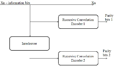
Turbo codes based on Convolutional codes are usually known as CTC (Convolutional turbo codes) [1] [8] [9] and those based on block codes as BTC (block turbo codes) [7]. Whereas in turbo codec encoder mechanism the encoder uses a stream-driven implementation and feeds the incoming information bits through to the output. In addition, it uses two recursive convolution encoders (RSC) [5] with one interleaver [4] [3]. The information bits are encoded using encoder-1, a recursive convolution encoder
are parity-1 bits. The interleaved bits are encoded by encoder-2 are parity-2 bits. The encoded bit streams with information bits are arranged in a systematic way. This systematic bit combination is transmitted at the receiver end.
Interleaver is the process of reordering a binary sequence in a systematic way. Convolutional codes are designed to combat random independent errors. However, errors typically come in bursts rather than randomly distributed. Interleaving can be used to disperse the burst errors, making them easier to correct.
NOTE: The turbo codec encoder and decoder interleavers should be identical. The interleaver order used here is as per pseudo random permutations of albert predetermined fashion.
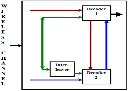
SOVA and log-MAP turbo decoding algorithms are the two prime candidates for decoding turbo codes [11]. In classical turbo decoder [12], at the receiver, the incoming symbol stream is sampled to create a soft input to the two decoders. A soft decoder creates a digital word from each sample using an ADC so that information about the magnitude as well as the state of the received symbol is retained. Recovered bits are given a weighting in the decoding process according to the confidence level from the sampling process. The process is known as soft input soft output (SISO) decoding [11] [12]. In novel turbo codec decoder mechanism we use two decoders and one .. At received data stream, the information bits and parity-1 bits are fed into decoder 1. The interleaved information bits and parity-2 bits are fed into decoder-2. The result of decoder-1 and decoder-2 is iterated two times to get final result.
2. NOVEL TURBO CODEC MECHANISM
© 2017, IRJET | Impact Factor value: 6.171 | ISO 9001:2008 Certified Journal
| Page 1040
Fig – 1: Block diagram of turbo codec mechanism2.1. Turbo Encoder:
We are considering the information bits as {x0, x1, x2, x3, x4, x5, x6, x7} = {1, 1, 0, 0, 1, 0, 1, 0}
[image:2.595.39.283.364.507.2]These information data bits are passed through turbo encoder and generate output at 1:3 ratios [10] [6].
Fig – 2: Block diagram of turbo Encoder
2.1.1. Recursive Convolutional Encoder:
. Fig – 3: Recursive convolution encoder internal schematic, State = U1U0
Here U1 and U0 are two flip flops with characteristic equation
Q(t+1) ≤ Q(t) (1)
= D (2)
Now U1 :-
Q1 (t+1) = Q0 (t) (3)
U0 :-
Q0 (t+1) = Xn⨁ Q0(t)⨁Q1 (t) (4)
= Q1(t)⨁Q1(t)⨁ Q0(t)⨁Xn (5)
= Q0(t)⨁Xn (6)
Output:-
P(x) = Q0(t)⨁ Xn (7)
RSC Encoder 1:
This encoder takes the information bits Xn and generates parity bits which are then passed to decoder 1 in turbo decoder block. The generation of parity bits follows a process using fig 3 where flip-flops with equations (1) to (7) are arranged. Tabulating these values as per equations and collecting the parity bits of recursive convolutional encoder 1 is the same process for the recursive convolutional encoder 2, where encoder1 and encoder 2 parity bits are collected. Let us first see the working of RSC encoder 1 and tabulate the values as follows,
Table -1: RSC Encoder 1 Output
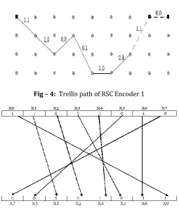
Output of RSC encoder 1 is 10010110
© 2017, IRJET | Impact Factor value: 6.171 | ISO 9001:2008 Certified Journal
| Page 1041
Fig – 4: Trellis path of RSC Encoder 1Fig – 5: Pseudo random interleaver (predefined pattern)
[image:3.595.311.559.155.277.2]The interleaver pattern is predefined and identical to the both sides of turbo codec. The sequence of the information bits is shuffled using this interleaver pattern. This interleaved information bits is passed through the recursive convolutional encoder 2 to generate parity bits. This follows the same process by using fig 3 and equation (1) to (7). We tabulate the bit values using XOR operator. These parity bits are arranged systematically with the information bits and parity bits of encoder 1 and form a 24 bit sequence.
Table -2: RSC Encoder 2 Output
[image:3.595.313.559.333.489.2]RSC encoder 2 output is 00110111 interleaved information bits with RSC encoder 2 output resulting a path through trellis [2].
Fig – 6: Trellis path of RSC Encoder 2
2.1.2. Arrangement of information bits and parity bits:
Fig – 7: Arrangement of information bits, parity bits 1 (encoder 1 output bits) and parity bits 2 (encoder 2 output
bits)
Information bits Parity 1 bits Parity bits 2
11001010 10010110 0011011
This 24 bits data is transmitted through channel and received at the receiving antenna and the received code word will be 110010101001011000110111
2.2 Turbo Decoder:
© 2017, IRJET | Impact Factor value: 6.171 | ISO 9001:2008 Certified Journal
| Page 1042
Fig – 8: Interleaver at turbo decoder blockInterleaved output = 00101011
Fig – 9: Block diagram of Turbo decoder
Information bits = 11001010
Parity bits 1 or Encoder 1 bits = 10010110 Parity bits 2 or Encoder 2 bits = 00110111
Interleaver = 00101011
2.2.1. Working of Decoder using XOR gate:-
At received data stream, the information bits and parity 1 bits are fed into decoder 1. The interleaved information bits and parity 2 bits are fed into decoder 2. The result of decoder 1 and decoder 2 is iterated two times to get final results.
Note:- “⊕” is XOR gate operator.
Decoder 1:-
Information bits ⊕ parity 1 bits 11001010
⊕ 10010110
---
01011100 -- Decoder 1 output ---
Decoder 2:-
Interleaved information bits ⊕ parity 2 bits
00101011
⊕ 00110111
---
00011100 -- Decoder 2 output ---
First Iteration:-
Information bits ⊕ decoder 1 ⊕ decoder 2
11001010
⊕ 01011100 ⊕ 00011100 ---
10001010 -- First iteration output ---
Second iteration:-
First iterated output ⊕ decoder 1 ⊕ decoder 2
10001010
⊕ 01011100
⊕ 00011100
---
11001010 -- Second iterated output = original input bits. ---
Hence we got the input information bits sequence at decoder in second iteration itself, which reduces latency and complexity.
3. CONCLUSION
This paper has proposed, for the first time, a novel turbo codec method of turbo codes which reduces the complexity of turbo decoder working by using a simple XOR gate. In particular, a new approach with two iteration and getting the original information signal. In earlier decoder algorithms SOVA and log-MAP turbo decoding algorithms were used for decoding turbo codes. On comparison, it is noted that proposed novel turbo codec mechanism reduces complexity. Turbo encoder detailed working mechanism is given in this paper. The interleavers were predetermined valued interleavers which is identical at both side of turbo codec mechanism.
[image:4.595.66.280.315.466.2]© 2017, IRJET | Impact Factor value: 6.171 | ISO 9001:2008 Certified Journal
| Page 1043
REFERENCES
[1] J. L. Massey, Threshold Decoding, MIT Press, Cambridge, Mass., 1963.
[2] Charan Langton, “Turbo coding and MAP Decoding-Example”, intuitive guide to principles of communications, 2006.
[3] H. R. Sadjadpour, N.J.A. Sloane, M. Salehi, and G. Nebe, “Interleaver Design for Turbo codes”, draft, November 10, 2000.
[4] Akash Kumar Gupta and Sanjeet Kumar, “VHDL Implementation of different Turbo Encoder using Log-MAP Decoder”, Journal of Tele- communications, Volume 2, Issue 1, February 2010.
[5] Mangapathi Narendra Reddy, P. Muralidhar and C.B. Rama Rao, “Design and Implementation of Custom Processor Architecture for Turbo Encoder and Decoder Using NISC” European Journal of Scientific Research ISSN 1450-216X Vol.36 No.1 (2009), pp.79-92 © Euro Journals Publishing, Inc. 2009
[6] S. Benedetto, G. Montorsi, “Design of parallel concatenated convolutional codes”, IEEE Trans. Commun., vol. COM-44, pp. 591-600, May 1996.
[7] R. M. Pyndiah, “Near-Optimum Decoding of Product Codes: Block Turbo Codes”, IEEE Trans. Commun., vol. 46, no. 8, pp. 1003-1010, Aug. 1998.
[8] R. M. Fano, “A Heuristic Discussion of Probabilistic Decoding”, IEEE Trans. Inf. Theory, IT-9, pp. 64-74, Apr. 1963.
[9] A. J. Viterbi, “Error Bounds for Convolutional Codes and an Asymptotically Optimum Decoding Algorithm”, IEEE Trans. Inf. Theory, IT-13, pp. 260-269, Apr. 1967.
[10] Rajeshwari. M. Banakar, “A Low power Methodology for Turbo Encoder and Decoder”, Department of Electrical Engineering, IIT-Delhi, India, July 2004.
[11] Costas Chaikalis, James M. Noras and Felip Riera-Palou, “Improving the reconfigurable SOVA/log-MAP turbo decoder for 3GPP” University of Bradford, Department of Electronics and Telecommunications, Bradford, West Yorkshire, BD7 1DP, UK.
[12] D. Kbaier Ben Ismail, C. douillard and S. Kerouedan, Electronics Dept, Ph.D defense, Monday 26th September 2011 page-2 Turbo codes. http://www-elec.enst-bretagne.fr/demos/principe/turbo_codes.htm