Finite Element Analysis of Doubly Curved Thin Concrete Shells with
Square and Rectangular plan 15mx15m and 15mx10m under
Uniformly Distributed Load using SAP2000
Danush Gangur L M
1, Sowjanya G V
2, Siddesh T M
31
PG Student, Department of Civil Engineering, SSIT, Tumakuru-572105, Karnataka, India
2Assistant Professor, Department of Civil Engineering, SSIT, Tumakuru-572105, Karnataka, India
3
Structural Design Engineer, Indiresh and Associates, Shivamogga - 577201, Karnataka, India
---***---Abstract:
A shell structure is a triple dimensional formation, thin in one aspect and long in the alternative two ways. They span over comparably huge areas, and hold thetested loads in a compelling way.They span over comparably
huge areas, and hold tested loads in a compelling way. They full fill their role by two separate systems. One is the space covering technique to examine the space, such as concrete slab or roof covering sheets in steel construction .These are supported by a second system of beams and columns which we may call the supporting system. In many steel buildings they are obviously separate and in R.C buildings also, they are treated as two separate systems. In reinforced concrete shells, however, the two functions of covering the space and supporting the covering system are integrated into one. The formation covers the slot externally beams and columns not over the buildings. In this study doubly curved shells which are analyzed using Finite Element software SAP 2000(v18) with new version. Doubly curved shells which are in square and rectangular plan having 15mX15m and 15mx10m are considered. The behavior of shells under
universally distributed load varying from 1to5 KN/mis
studied .In this case study deflection curves, membrane stress and stress contour diagram are obtained. It is observed that with the increase in rise and thickness of funicular shell the deflection are reduced. The stresses in the membrane reduce with the increase in rise and thickness of concrete funicular shell.
Key Words: Deflection, Edge beam, Funicular shell, Finite Element Method, Membrane stress, Rise, SAP 2000, Thickness.
1. INTRODUCTION
The shells of double curvature are stronger when compared to shells of single curvature, equivalent to cylindrical shells. Further, the arch distributes the load in all paths equally and resists the impact of loading at any point. These shells are used as floors and also as roofs. Funicular shells are a class of doubly curved shells, the form of which satisfies the desired state of stress in its body for the given loading and boundary conditions. The state of stress favored in an unreinforced concrete thin shell will be pure compression unaccompanied by shear and bending stresses. Under different conditions of
loading, bending moments would strengthen and the shell will not behave only as a funicular element. Analytically, it's possible to compute the funicular surface of any ground plan for the given loading conditions.
The shapes of these shells are chosen that, under UDL, in a membrane state of stress, they develop only pure compression unaccompanied by shear stress. Thus no reinforcement is necessary, except in the edge members. In the lower portion steel reinforcements are required to counter the tensile stresses. It can be converted as compression structure by inverting it, with a considerable reduction in the quantity of steel & cement. Compression structures are used in the form of vault, arches, domes and doubly curved thin shells also known as funicular shells are widely used in the construction of forts and temples. These structures are the best proof for the durable performance of shell structures. The funicular shell roof structure is one such compression structure, which can be built by utilizing waste materials and natural resources can be conserved effectively and use of expensive steel and cement are optimized. Diagonal grid of funicular shell gives the semblance of a largest space. A typical view of funicular shells used for a roof construction is shown in figure 1.
Fig-1: Typical view of Funicular Shell roof.
2. Literature review
© 2017, IRJET | Impact Factor value: 5.181 | ISO 9001:2008 Certified Journal
| Page 561
shells which might be in square plan having 10mX10m and 15mX15m are considered and shells in rectangular plan having dimensions 10mX15m and 15mX20m are considered. The behavior of shells under self-weight, are living load various from 0-20KN/m (UDL) is obtained. On this case study deflection curves, membrane stress and stress contour diagram are acquired. It is determined that with the development in rise and thickness of funicular shell the deflection are diminished. The membrane stresses reduces with the development in rise and thickness of concrete funicular shell. The aim of this study is to develop shells of different sizes and investigation is done on the shells by finite element analysis under given UDL, to discover the behavior of shells in various circumstances making use of standard software, Structural Analysis Package (SAP 2000).
P. Sivakumar, K. Manjunatha, Harish B. A (2015) have done the work on Concrete funicular shells with square in ground plan having 80mm rise are analyzed for UDL. specimen of dimension 1.08m x 1.08m in arrangement having rectangular edge beam of dimension 50mm x 40mm are prepared using M20 grade concrete. By masonry mould method the pre-casting of the specimens is done and specimens are prepared with 25mm and 20mm thickness and moist cured for 28 days earlier than testing. Over the shell specimens uniformly distributed load is applied & the corresponding deflections and strains are noted. To associate experimental outcomes to logical results, the restricted aspect performance is recognizable to figure out comparable model. Conclusions got to avenue comparing the experimental and investigative results.
Siddesh T M, Harish B A, Dr. K Manjunatha,(2016) In this study doubly curved thin shells are analyzed using Finite Element software SAP 2000 with new version. Doubly curved shells which are in rectangular plan having 1mX0.7m are considered. The behavior of shells under concentrated load varying from 1to5KN is studied and compared with the slabs of same dimension and thickness .In this case study deflection curves, membrane stress and stress contour diagram are obtained. It is observed that with the development in rise and thickness of funicular shell the deflection are reduced. The membrane stresses decreases with the development in rise and thickness of funicular shell.
3. Objectives of the work
Doubly curved thin concrete shells of square and rectangular in ground plan, with doubly curved surfaces and various rises and thickness are analyzed by using finite element method. To study the behavior of funicular shells under UDL. In this work an analytical investigation on doubly curved funicular shell with ground plan ratio 15x15 and 15x10 subjected to uniformly distributed load with distinct rise at L/10 and L/20 with thickness of 20mm, 40mm and
[image:2.595.312.555.153.342.2]50mm is offered. The dimensions of the shells with their rise and thickness are shown in Table 1.
Table -1: Size of shells
SHELLS WITH VARYING RISES & THICKNESS
Geometry of the shells
Designation of the shell
Plan dimensions in
m
Rise (R) in
mm
Thickness in mm
Square
FS I 15x15 1000 50
FS II 15x15 1000 40
FS III 15x15 1000 20
FS IV 15x15 750 50
FS V 15x15 750 40
FSV VI 15x15 750 20
Rectangle
FS VII 15x10 1000 50
FS VIII 15x10 1000 40
FS IX 15x10 1000 20
FS X 15x10 750 50
FS XI 15x10 750 40
FSV XII 15x10 750 20
4. Finite Element Modeling and Analysis
The shells were modeled with dimensions as mentioned in “Table 1”,the rise of shell is taken at L/10 and L/20 where L is the span 15m and the edge beam thickness is taken as twice or thrice the thickness of shell, and all models are fixed supported at the edges. For material properties, M25 grade concrete properties are considered.
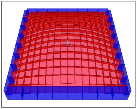
The models were discritized and subjected UDL varying from 1-5kN .The 3D model of FS I is shown in Figure2, discritized model is shown in Figure3 and model after applying load is shown in Figure 4.
[image:2.595.318.551.527.712.2]Fig-3: Discritized model of shell FS I
Fig-4: FS I Shell model after loading
Table-2: Stress and Deflection values of FS I
Load in kN/m Stress in N/mm2 Deflection in mm
1 0.1077 -0.4585
2 0.2154 -0.9170
3 0.3237 -1.3755
4 0.4308 -1.8340
5 0.5385 -2.2926
After applying load the corresponding deflections and stresses at nodes were noted and graph is plotted with corresponding load and distance. The stress contour and deflected model is shown in Figure 5 and Figure 6 respectively and the graph of stress and deflection values for shell FS I is shown in Chart 1 and Chart 2 respectively. Similarly analysis is carried out for every shell and the values are obtained.
Fig-5: Stress contour of shell FS I
Fig-6: Deflection model of shell FS I
Chart-1:Graph showing Stress v/s Load for FS I
Chart-2: Graph showing Deflection v/s Load for FS I
The maximum deflection and stress are obtained at the center of the shell, values are tabulated in Table 2 with corresponding loadings.
Table-3: Stress and Deflection values
FS II FS III
Load in KN/m
Stress in N/mm2
Deflection in mm
Load in KN/m
Stress in N/mm2
Deflection in mm 1 0.21730 -0.5853 1 1.1490 -1.1840
2 0.47713 -1.1705 2 2.2922 -2.3690
© 2017, IRJET | Impact Factor value: 5.181 | ISO 9001:2008 Certified Journal
| Page 563
FS IV FS V
Load in KN/m Stress in N/mm2 Deflection in mm Load in KN/m Stress in N/mm2 Deflection in mm 1 0.08192 -0.7345 1 0.19017 -0.9228
2 0.16380 -1.4690 2 0.38034 -1.8456 3 0.24577 -2.2034 3 0.57051 -2.7685 4 0.32769 -2.8978 4 0.76068 -3.6913 5 0.40961 -3.6724 5 0.95085 -4.6141
FS VI FS VII
Load in KN/m Stress in N/mm2 Deflection in mm Load in KN/m Stress in N/mm2 Deflection in mm 1 0.9520 -1.8802 1 0.07340 -0.1725
2 1.9041 -3.7605 2 0.14681 -0.3449 3 2.8813 -5.6407 3 0.22021 -0.5174 4 3.8083 -7.5209 4 0.29388 -0.6898 5 4.7605 -9.4012 5 0.36701 -0.8623
FS VIII FS IX
Load in KN/m Stress in N/mm2 Deflection in mm Load in KN/m Stress in N/mm2 Deflection in mm 1 0.13366 -0.2199 1 0.4598 -0.4954
2 0.26733 -0.4399 2 0.9519 -0.9907 3 0.40100 -0.6598 3 1.4279 -1.4868 4 0.53460 -0.8798 4 1.9039 -1.9815 5 0.66830 -1.0997 5 2.3799 -2.4768
FS X FS XI
Load in KN/m Stress in N/mm2 Deflection in mm Load in KN/m Stress in N/mm2 Deflection in mm 1 0.4430 -0.2652 1 0.10607 -0.3235 2 0.8801 -0.5303 2 0.2120 -0.6471 3 1.3201 -0.7955 3 0.3182 -0.9706 4 1.7602 -1.0606 4 0.4242 -1.2941 5 2.2010 -1.3258 5 0.5303 -1.6171
FS XII
Load in kN/m Stress in N/mm2 Deflection in mm
1 0.5413 -0.6583
2 1.0827 -1.3166
3 1.5927 -1.9748
4 2.1654 -2.6331
5 2.7068 -3.2914
Table-4:
Analysis Summary of FS I, FS II and FS III
Under uniformly distributed load condition from the analysis of FS I, FS II and FS III in case of stress there is more tension at edges and compression in other regions. In case of deflection there is more deflection around the center region .
Chart-1 Shows the rise in deflection with decrease in thickness, we can observe the gradual increase in deflection in 50mm and 40mm thickness shell, the rate of increase in
deflection is in 20mm shell due to the very low thickness.
Chart-2 Shows the rise in membrane stress with decrease in thickness of shell, the variation is less in lesser loads.
Chart-3: Graph representing variation of membrane stress for corresponding loads.
Chart-4: Graph representing variation of deflections for corresponding loads.
5. Conclusion
The following conclusions are obtained from the outcomes of the investigation:
1. There is decrease in deflection with increase in rise and thickness of the shell.
2. There is decrease in membrane stresses with increase in rise and thickness of shell.
3. It is observed that with the increase in thickness of funicular shell the deflection of shell are reduced. 4. Membrane stresses decreases with the increase in
thickness of concrete funicular shell.
5. The Maximum tensile stresses are developed at shell corners.
6. The maximum compressive stresses are developed at the shell edge.
7. The deflections and stress are reduced with use of reinforcement in shells.
8. Rate of deflection is more in case of FSIII when compared to FSI and FSII due to the lesser thickness.
9. Difference in Membrane stress is less in case of UDL due to high rise and uniform distribution of loads.
REFERENCES
[1] Ramaswamy G .S, “Design and Construction of concrete
shell Roofs”.CBS publishers,1986.
[2] Harish B.A, Venkataramana N, Manjunatha K(2015)
“Finite Element Analysis OF Doubly Curved concrete shells”.IJESIT,Volume 4,Issue 5,September 2015.
[3] Siddesh T.M, Harish B A, Dr. KManjunatha,(2016)“Finite
Element Analysis Of Funicilar Shells With Rectangular Plan Ratio 1:0.7 Under Concentrated Load Using SAP ”. IRJET, Volume 3, Issue 9, September 2016.
[4] IS 2210 (1988): Criteria for Design of Reinforced
Concrete Shell Structures and Folded Plates.
[5] IS 6332 (1984): Code of Practice for Construction of Floor
and Roofs Using Precast Doubly-Curved Shell Units.
BIOGRAPHIES
Danush Gangur L M is presently studying M.Tech (Computer Aided Design of Structures) in SSIT, Tumakuru, Karnataka. He received his B.E Degree in Civil Engineering from VTU during 2010-2014. The area of research interest include FE analysis of thin concrete shells.
Sowjanya G V is presently working as Assistant professor, Dept of Civil Engineering at SSIT, Tumakuru, Karnataka. She had obtained her M.Tech degree in Structures. Her areas of research interest include Earthquake Resistant design of Buildings.