Design And Fabrication Of Unmanned Fire Fighting Vehicle
Cenno Franjo
1, Jerry Yacob
2, Krishnadas
3,Teenusmon MT
4, Prof Georgekutty S Mangalathu
51,2,3,4-B-Tech Degree student, Mechanical Engineering, Mar Athanasius College of Engineering,
Kothamanglam ,Kerala, India
5-Associate Professor, Dept. of Mechanical Engineering, Mar Athanasius college of Engineering, Kothamangalam, Kerala, India
---***---Abstract
- The risks involved in fire fighting and fire rescue operations are very high. The aim of this project is to develop a remotely controlled vehicle which could perform fire fighting operations and thereby reducing the risk factor for firemen. The vehicle is compact enough and will provide reach to areas which are inaccessible or dangerous for humans. The vehicle will be driven by a tank tread mechanism. It will be equipped with an arrangement for a nozzle through which water or any other fire extinguishing liquid (like foam) could be pumped. The vehicle is equipped with a micro controller unit, which controls all aspects of the vehicle and operates it according to the instructions received wirelessly. Live video feedback from the vehicle is obtained with the incorporation of a camera, which gives the controller an idea of the surroundings. The vehicle is so designed such that it can withstand the thrust encountered during operation. The vehicle is capable of indoor as well as outdoor fire fighting operations. Reliability, manoeuvrability and compactness ensures that the vehicle to perform operations that aids the fireman indoors.Key Words: Remote Control, Fire fighting, Micro controller, Nozzle, Live video.
1.INTRODUCTION
Designing of the basic structure of the vehicle is to be done primarily. The design process will be performed in Solid works CAD software. Finite elemental force analysis will be performed using suitable simulation software and obtained results will used for analysis and optimization of the design. Thermal analysis will also be conducted to check the vehicle performance during fire fighting operations. Materials required for the development of the vehicle are to be determined on basis of structural and fire-resistant properties. The processes and procedures for fabrication are determined on the basis of requirements and availability of resources. Drive for the vehicle is to be obtained from a dc motor. Since it’s been planned to obtain directional control by alternative operation of tank tread on both sides, so two motors are needed. The selection of motor based on the torque and speed requirements is to be done. The dc power source for operating the motor are obtained from the batteries mounted on the vehicle itself. Fire resistivity can be enhanced by giving a coating of fire retardant materials. Water or the other fire extinguishing fluid is pumped from an external source through a pipe to the vehicle. A direction controllable nozzle is embedded through which any required angular position can be setup, thereby facilitating us to target any specific area of fire. Realization of the direction of
movement, identification of obstacles, location of fire etc. is obtained through a live camera feed. Assembly of the above-mentioned components in their respective slots will ensure effective and reliable working of the vehicle as a complete system. Firemen are now made capable of remotely extinguishing fires. By incorporating this vehicle in fire fighting operations, firemen are kept away from direct contact fire and its risks. Moreover, it can be useful in certain types of incidents where the environment will be very dangerous for humans such as the hazardous chemicals, the chemical tanks and radioactive areas. Also, the vehicle is capable of performing basic functions of a fireman, so manual labour of firemen could be minimized to an extent. These vehicles could be purchased by small industries and residential complexes. They could be used for preliminary fire fighting by anyone with minimal training. The main objective of the project is to reduce the risks to human life during fire fighting operations.
2. COMPONENTS
2.1. ARDUINO UNO
Fig1. Microcontroller ATmega328P
Operating Voltage: 5v Input Voltage: 7-20v
Digital I/O Pins: 14 (of which 6 provide PWM output)
Analogue Input Pins: 6
DC Current per I/O Pin: 20 mA DC Current for 3.3V Pin: 50 mA
Flash Memory: 32 KB of which 0.5 KB used by boot loader
SRAM: 2 KB EEPROM: 1 KB Clock Speed: 16 MHz Length: 68.6 mm
2.2.BLUETOOTH MODULE HC 05
Fig.2 Bluetooth module HC 05
Hardware features: Typical -80dBm sensitivity Up to +4dBm RF transmit power Low Power 1.8V Operation ,1.8 to 3.6V I/O PIO control UART interface with programmable baud rate With integrated antenna With edge connector
[image:2.595.382.485.206.291.2]2.3. CHANNEL 5V RELAY MODULES
Fig.3 Channel 5v Relay Modules
4-Channel Relay interface board, and each one needs 15-20mA Driver Current
Both controlled by 12V and 5V input Voltage Equipped with high-current relay, AC250V 10A ;
DC30V 10A
Standard interface that can be controlled directly by microcontroller (Arduino, 8051, AVR,PIC, DSP, ARM, ARM, MSP430, TTL logic active low)
Indication LED’s for Relay output status.
2.4. MOTOR
Fig.4 Wiper motor
Wiper Motor Specifications:
Linkage type 12 Volts / 24 Volts
60 Wipes per minute on load (High speed) Single speed / two speed with thermal cut out 40 Wipes per minute on load (Normal speed)
2.5. TB 6600 STEPPER MOTOR DRIVER
Fig .5 TB 6600 stepper motor driver
Specifications:
[image:2.595.313.551.352.457.2]2.5.1 STEPPER MOTOR DRIVER CONNECTION
Fig. 6 Stepper motor driver connection
2.7 7805 VOLTAGE REGULATING IC
Fig.7. 7805 voltage regulating IC
Input Current: 0~5A
Output Current: 0.5~4.0A
Control Signal 3.3~24V
Power (MAX): 160W
Micro Step: 1, 2/A, 2/B, 4, 8, 16, 32
Temperature: 10~45℃
Weight: 0.2 kg
[image:2.595.337.528.492.620.2]3 DESIGN OF COMPONENT
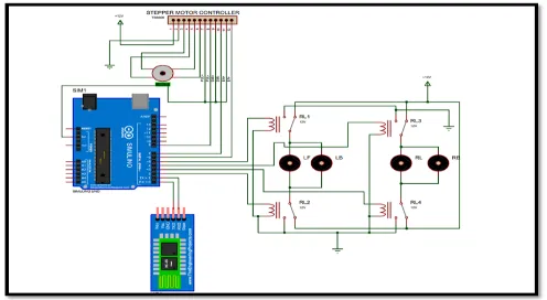
3.1DESIGN OF ELECTRONIC CIRCUIT
• Electronic components required for remote controlling of the vehicle was acquired and programmed.
• The controller unit used was ARDUINO UNO. • Controller chip is fitted with a Bluetooth module
which can receive and send signals.
• Maneuvering of the vehicle could be done wirelessly over Bluetooth using a mobile application. • Controller chip is connected to a relay module
which in turn controls the current flow to the motors.
[image:3.595.37.285.299.435.2]3.2 ELECTRONIC CIRCUIT
Fig .8 Electronic circuit for motor control and nozzle movement
3.3 ARDUINO PROGRAMMING
#define relay1 2 #define relay2 3 #define relay3 4 #define relay4 5
int PUL=8; //define Pulse pin int DIR=7; //define Direction pin int ENA=6; //define Enable Pin char val;
void setup() {
pinMode(relay1,OUTPUT); pinMode(relay2,OUTPUT); pinMode(relay3,OUTPUT); pinMode(relay4,OUTPUT); digitalWrite(relay1,LOW); digitalWrite(relay2,LOW); digitalWrite(relay3,LOW);
digitalWrite(relay4,LOW); pinMode (PUL, OUTPUT); pinMode (DIR, OUTPUT); pinMode (ENA, OUTPUT); //mySerial.begin(9600); Serial.begin(9600); } void loop() {
if(Serial.available() >0 ) { val = Serial.read(); Serial.println(val); delay(400); } if( val == 'A' )
{ digitalWrite(relay3,LOW); digitalWrite(relay1,LOW); digitalWrite(relay2,HIGH); digitalWrite(relay4,HIGH);} //Back
else if( val == 'B' ) { digitalWrite(relay3,HIGH); digitalWrite(relay1,HIGH); digitalWrite(relay2,LOW); digitalWrite(relay4,LOW); } //Left
else if( val == 'C' )
{ digitalWrite(relay3,LOW); digitalWrite(relay1,HIGH); digitalWrite(relay2,LOW); digitalWrite(relay4,HIGH); } //Right
else if( val == 'D' ) { digitalWrite(relay3,HIGH); digitalWrite(relay1,LOW); digitalWrite(relay2,HIGH); digitalWrite(relay4,LOW); } //Stop
else if( val == 'I' )
}// UP
else if( val == 'X' )
{ for (int i=0; i<6400; i++) { digitalWrite(DIR,LOW); digitalWrite(ENA,HIGH); digitalWrite(PUL,HIGH); delayMicroseconds(50); digitalWrite(PUL,LOW); delayMicroseconds(50); } }//DOWN
else if( val == 'Y' ) { for (int i=0; i<6400; i++) { digitalWrite(DIR,HIGH); digitalWrite(ENA,HIGH); digitalWrite(PUL,HIGH); delayMicroseconds(50); digitalWrite(PUL,LOW); delayMicroseconds(50); }}}
3.4 THRUST CALCULATION
Discharge
45lpm=45/(1000*60) =7.5x10⁻⁴
Thrust = (Mass Flow Rate) xVelocity =0.75x19.488
=14.616N
Moment about ‘O’ due to thrust form the nozzle =14.616x27 Ncm
=394 Ncm
Calculated moment about ‘O’ for toppling =110x26 Ncm
=2860 Ncm
Fig.9 2D Drawing
4 METHODOLOGY
Designing of the basic structure of the vehicle is to be done primarily. The design process will be performed in Solid-works CAD software. Finite elemental force analysis will be performed using suitable simulation software and obtained results will used for analysis and optimization of the design. Materials required for the development of the vehicle are to be determined on basis of structural and fire-resistant properties. The processes and procedures for fabrication are determined on the basis of requirements and availability of resources. Design of the tank tread mechanism is to be done. Drive for the vehicle is to be obtained from a dc motor. Since it’s been planned to obtain directional control by alternative operation of tank tread on both sides, so two motors are needed. The selection of motor based on the torque and speed requirements is to be done. The dc power source for operating the motor are obtained from the batteries mounted on the vehicle itself. Fire resistivity can be enhanced by giving a coating of fire retardant materials. Water or the other fire extinguishing fluid is pumped from an external source through a pipe to the vehicle. A direction controllable nozzle is embedded through which any required angular position can be setup, thereby facilitating us to target any specific area of fire. Realization of the direction of movement, identification of obstacles, location of fire etc. is obtained through a live camera feed. Assembly of the above-mentioned components in their respective slots will ensure effective and reliable working of the vehicle as a complete system.
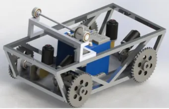
4.1 MODELLING IN SOLID-WORKS
[image:4.595.349.520.475.585.2]Fig.10 Solid Work Skelton Form
5. RESULTS AND CONCLUSION
[image:5.595.68.258.133.257.2]5.1 RESULT BASED ON STRUCTURAL ANALYSIS
Fig.5.1 Structural analysis
On the basis of ANSYS analysis the maximum stress developed on the structure was obtained as 22 Mpa at the base frame. The yield strength of galvanized ion is around 80-120Mpa. Since this obtained value is much lower than the yield strength of the galvanized iron, the structure is safe. The minimum value is found to be 2653.1pa.
[image:5.595.58.263.402.525.2]5.2 RESULT BASED ON THERMAL ANALYSIS
Fig.5.2.Thermal analysis
The thermal analysis was conducted on the vehicle. The external conditions under consideration for the thermal analysis were 10 minutes of continuous operation of the vehicle in an atmospheric condition of 1000C.The maximum temperature developed on the surface was obtained as 92.5420C and the temperature of the internal components were found to be within the range of 25-350C.From these results it is clear that the internal components especially electronic components are safe to work within this range of temperature. Hence vehicle can perform uninterrupted motion and is safe to operate under the above considered conditions.
5.3 RESULT BASED ON THRUST CALCULATION
The moment due to the discharge of the nozzle calculated with respect to contact point between the rear wheel and ground is obtained as 394Ncm and the moment due to the weight of the body acting at the centre of the body is found
to be 2860Ncm. The results shows that the weight of the body is much enough to withstand the thrust due to the nozzle discharge.
5.4 CONCLUSION
• The fire fighting vehicle which can be remotely controlled was designed and analyzed.
• The Nozzle can be adjusted through various angles and water can be sprayed to a distance of 10 meters.
• The vehicle can be manoeuvred over different types of terrain.
• The Live video feed from the vehicle can be viewed. • Safety and health of fire fighters can be ensured by the fire fighting vehicle. With necessary additional modifications this vehicle can be an advanced addition to the fire fighting department
REFERENCES:
1. Chee Fai Tan, S.M. Liew, M.R. Alkahari, S.S.S. Ranjit, M.R. Said, W. Chen, G.W.M. Rauterberg, D. Sivakumar and Sivarao: Fire Fighting Mobile Robot: State of the Art and Recent Development Up-Scaling and Optimization of Fire Fighting Ground Vehicle Track System.(2012)
2. CheeFai Tan, Ranjit Singh Sarban Singh, V.K. Kher and H.F. Kong: Up-Scaling and Optimization of Fire Fighting Ground Vehicle Track System.(2010)
3. Sunil Mathew, Gaikwad Sushanth, KR Vishnu, V. Vishnu Nair, and G. Vinoth Kumar: Fabrication of Fire Fighting Robot(2010)
4. C. Theobald: The Effect of Nozzle Design on the Stability and Performance of Turbulent Water Jets.(2011)
5. H. Hazwani Dzulkaflia, Faiz Ahmada, Sami Ullahb, Patthi Hussaina, Othman Mamata,Puteri S.M. Megat-Yusoffa: Effects of talc on fire retarding, thermal degradation and water resistance of intumescent coating.(2013)
6. AlHaza Ta, Alsadoon Aa, Alhusinan Za, Jarwali Ma , Alsaif Kb. New Concept for Indoor Fire Fighting Robot.(2015)
7. Yuhki Kitazono, Shota Nakashima, Lifeng Zhang, Seii Chi Serikawa: Proposal of optical sensor with large area using universal remote controller.(2010)
BIOGRAPHIES:
Cenno Franjo,
B-Tech Degree student Mechanical Engineering Mar Athanasius College of Engineering, Kerala, India
Jerry Yacob,
B-Tech Degree student Mechanical Engineering Mar Athanasius College of Engineering, Kerala, India
Krishnadas,
B-Tech Degree student Mechanical Engineering Mar Athanasius College of Engineering, Kerala, India
Teenusmon MT, B-Tech Degree student Mechanical Engineering Mar Athanasius College of Engineering, Kerala, India 2nd Aut
hor Photo
4th Author
Photo 3rd Auth or