© 2017, IRJET | Impact Factor value: 5.181 | ISO 9001:2008 Certified Journal
| Page 2662
FBG INTERROGATOR COMMUNICATION WITH THE EMBEDDED SYSTEM
Akshaya D
1, RK Karunavathi
21
M.Tech Scholar Digital Electronics and Communication, Dept. of Electronics and Communication Engineering
BIT, Bangalore, Karnataka, India
2 Associate Professor Dept. of Electronics and Communication Engineering BIT, Bangalore, Karnataka, India
---***---Abstract -
FBG sensors are the optical sensors which are sensitive to the external environmental conditions like temperature, pressure, strain. This feature of the FBG sensors make them suitable for many applications where electrical sensors are to be replaced due to their sensitivity to the electromagnetic interference and other radio frequency sources. FBG sensors are compact in size and their performance are not affected by the electrical sources. The sensed parameters of the FBG sensor should be analyzed using the interrogator monitor. To measure and test these external parameters the computer based application is used, which is connected to the interrogator. In all most every application where the FBG sensor is used to measure the external parameters, interrogator used a specific software which is installed in the PC. This paper aims to eliminate the use of software to measure and test the FBG sensor results. Instead it demonstrates the use of embedded system which communicates with the interrogator to perform measurement analysis.Key Words: FBG; Interrogator; Embedded system; Temperature; Strain; Stress.
1.INTRODUCTION
In some applications external parameters like temperature, pressure, strain should be monitored continuously for their better performance. Several low cost FBG interrogator systems were developed [1-3] to perform wavelength analysis of the FBG sensor. Compared to that of the electrical sensors, FBG sensors have higher sensitivity to the above mentioned parameters and are insensitive to electrical sources. This makes wide spread use of FBG sensors in many applications. FBG sensors can also be used to measure ultrasound, magnetic fields, acceleration and vibration [3]. Multiple FBG sensors are used in the aircrafts [4], civil structural monitoring, monitoring wind turbines [2], transformer monitoring. The sensed results of the FBG sensors are analysed using different interrogation techniques. In large scale applications FBG arrays can be used to measure different parameters [5]. Single optical fiber with multiple gratings results in a fiber bragg grating array. Spectroscopy based interrogator is the recent development for numerous microwave photonics applications [6]. Many different interrogators are used which is compatible with that of different FBG sensors. But the portable interrogation system will be of great benefit [7] which uses temperature
stable SLED source and optical Fabry-Perot filter. In every interrogation system the interrogation monitor communicates the software which is designed to set the basic settings of the interrogator and to measure the FBG sensor results. In the process of making portable and flexible interrogator system, one idea is to replace the software application with that of the embedded system. This paper presents the method to replace software with that of the interrogator. For high resolution, high speed, and better SNR an interrogation method based on wavelength-swept lasers [8] is used.
2. BACKGROUND
2.1 Basic principle of the FBG sensor
The fiber bragg grating sensors are optical sensors, formed by writing gratings inside the optical fiber. The refractive index changes periodically inside the core of the optical fiber when it is exposed to the UV radiations. In the interrogation system SLED is used as an optical source that illuminates the broadband light on the FBG sensor. The FBG sensor works with the principle of fiber bragg wave length. When a broadband light illuminates on the FBG sensor, it transmits all other wavelength except the one wavelength which is called bragg wavelength. It reflects the bargg wave length, and the shift in the bragg wave length takes place based on the external parameters like temperature, pressure and strain. The shift in the bragg wavelength gives the amount of external parameter that is experienced by the FBG sensor. The bragg wave length is given as :
Where , is the bragg wavelength, n is the refractive index, ʌ is the spacing between the gratings. The reflected wavelength is given to the interrogator that performs wavelength analysis. The 3 port optical circulator is used to connect between optical source, FBG sensor and the interrogator. The figure 1 shows the basic settings of the interrogation system.
© 2017, IRJET | Impact Factor value: 5.181 | ISO 9001:2008 Certified Journal
| Page 2663
then converted into electrons and are digitized, read outthrough the USB port of the interrogator. The interrogator is connected to the PC/Laptop which is installed with the specific software. The results of the FBG sensor tested and analyzed with the software installed in the PC.
Fig-1: Basic interrogation system
In the interrogation system, the optical source is connected to the first port, FBG sensor to the second port and interrogator to the third port of the circulator. The broad band light travels from first port to the second port of the circulator to illuminate on the FBG sensor. Based on the external parameters sensed by the FBG sensor, shift in the Bragg wavelength occurs and is transmitted from second port to the third port of the circulator where interrogator is connected. The figure 2 below shows the reflected light from the FBG sensor.
Fig-2 Reflected light from FBG sensor
The spectrometer used in the interrogator can be communicated in three ways:
Software
Dynamic link logic(DLL)
Firmware commands
To communicate with the software, the software should be installed in the PC. Different software’s can be designed in accordance with that of the spectrometer and detector used in the interrogator system using different programming languages. To communicate using DLLs the user must write a sort of a program in any programming language which allows using external libraries. To communicate using firmware commands one needs any terminal program, which allows a connection via virtual COM-port.
To replace the software with that of the embedded system, the spectrometer is communicated through firmware commands. These commands are sent through the embedded
system and the response from the interrogator is received by the embedded system which is displayed on the screen. 2.2 Transformer oil testing
The transformer oil is used as coolant which conducts heat away from the transformer coil. The core and windings of the transformer are fully immersed in the transformer oil which act as an insulating element. The temperature of the transformer increases at peak periods when there is increase in demands for electricity generation and distribution networks. This causes failure in the transformer due to its breakdown. Hence the temperature of the transformer can to be monitored by using FBG sensors. Since the transformer oil acts as coolant in the transformer its temperature should be monitored by using FBG sensor. The temperature at which the transformer oil produces vapours to occur a flammable mixture with air is known as its flash point. In general the flash point of the transformer oil is more than C(> C). The temperature of the transformer oil should be lower than that of the flash point. Temperature at which oil just begins to flow under standard test condition is known as pour point of the transformer pour point of the transformer is important at the places where weather condition is ultimately cold.
In the transformer oil testing procedure, two fiber bragg grating needle temperature sensors are used among which one is place at 60mm from the base level of the kettle and the other one is placed at 110mm from the base level of the kettle. The transformer oil is heated up to 70 degrees Celsius and is poured into the kettle. The oil drainer is attached to the kettle when it drains the oil, after some time the oil in the kettle crosses below the upper level sensor and hence sudden changes in the sensor temperature occurs from 70 degrees Celsius to 48 degrees Celsius. When the oil drains the lower level sensor, the temperature of the sensor changes from 70 degrees Celsius to 60 degrees Celsius. Figure 3 shows the graph of the temperature oil testing result.
Fig-3. oil testing result graph
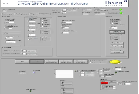
In this testing procedure the interrogator communicates with the software where the general parameters of the spectrometer and the image sensor in the interrogation
circulator
Optical
source
© 2017, IRJET | Impact Factor value: 5.181 | ISO 9001:2008 Certified Journal
| Page 2664
system are set by using the software to perform measuringresults which is shown in figure 4.
In the software, some of the interrogator parameters that to be set are camera setup, interrogation set up, file set up, buffer set up. The camera set up includes maximum scan rate of the image sensor, exposure time of the detector and the offset voltage to eliminate the offset error of the image sensor.
In the method of replacing the software with that of the embedded system, these parameters are set by using firmware commands that are sent through the embedded system.
Fig -4. Interrogator parameters setting by using software.
3. SELECTTING SUITABLE E EMBEDDED SYSTEM
Suitable embedded system should be chosen so that it can send and receive the data from the interrogator. The interrogator has the 3 main port: power port, parallel I/O port, and the micro USB port. The data communication takes place through the micro USB port. The embedded system is chosen in such a way that it is capable of detecting the USB device (IMON interrogator) and performs the enumeration process to initiate the communication with the interrogator. The raspberry pi is the embedded system which is chosen to communicate with that of the interrogator. The raspberry pi system is similar to that of the computer which is capable of communicating with that of the USB peripheral devices. The raspberry pi is having HDMI port where HDMI display should be connected and it is having the mocro USB port for the power supply, Ethernet port to access to the internet. Mouse, keyboard and other USB devices can be connected through USB ports.4.
FBG SENSOR TESTING BY USING EMBEDDED
SYSTEM
4.1 Experimental setup
The experimental set up includes the raspberry pi connected to the interrogator. The FBG needle temperature sensor and the conventional electric thermocouple sensor are placed inside the kettle that contains the water at normal temperature. The SD card installed with the noobs should be inserted to the raspberry pi. NOOBS is an easy way to install
the raspbian operating system. When the SD card is inserted to the raspberry pi, it will boot up the raspberry pi and different operating system can be downloaded using NOOBS. Raspbian operating system should be installed using NOOBS. Python programming is done in the raspberry pi to send the firmware commands to the interrogator through the USB port and to receive the replay from the interrogator that should be displayed on the HDMI monitor and the LCD display. When the interrogator is connected to the raspberry pi the enumeration process will take place. By using the lsusb and sudo dmesg –c LINUX commands in the raspberry pi terminal window, the details of the USB device like product ID and the vendor ID is obtained.
The USB details is shown in figure 5. The FTDI USART to USB converter is used in the interrogator which makes USB port available in the interrogator through which the commands to be sent to the interrogator.
Fig-5. USB details of the devices connected raspberry pi The figure 9 shows that the FTDI USB device converter now attached to ttyUSB0. The ttyUSB0 is the built in USB on the raspberry pi where tty is the associated terminal with the current process. The interrogator is connected to the ttyUSB0 of the raspberry pi and hence in the python program, when defining the USB device (IMON interrogator) ttyUSB0 should be mentioned.
4.2 Basic settings of the interrogator using firmware commands
General parameter setting:
1. *IDN? –This command gives the device ID of the spectrometer used in the interrogator.
[image:3.595.50.278.251.404.2] [image:3.595.318.565.315.424.2]© 2017, IRJET | Impact Factor value: 5.181 | ISO 9001:2008 Certified Journal
| Page 2665
Fig-6. Setting integration time
3. *PARAmeter:ADCResolution? –This command gives the information about the size of the analog to digital converter used in the interrogator. For example, 16 bit and 32-bit ADC.
4. *PARAmeter:PIXEL? -This command gives the number of pixel information of the image sensor. 256-pixel image sensor is used in the interrogator. 5. *PARAmeter:BAUD 115 -This command is used to change the baud rate of the interrogator to 115200 baud this result is shown in the figure 7. 3 baud rates are supported by the interrogator (IMON), the default baud rate is 921600, and other two baud rates are 115200 and 38400.
Fig-7: Baud parameter
Time settings: scan time of the detector which is used in the interrogator need to be set. Some of the commands for time setting is given below.
1. *PARAmeter:SDELay 10 –This command sets the scan delay of the interrogator 10ms which is shown in the figure 8. The scan delay is the time difference between the initiating a measurement and its real start of measurement.
Fig-8. Scan delay setting
2. *PARAmeter:FASTScan 10 –Fast scan time is the time taken for next fast scan. This command sets the fast scan time to 10ms.
Settings for measurements: The measurement settings consist of some commands to perform the measurement of the FBG temperature sensor.
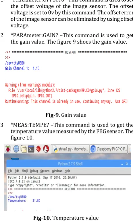
1. *PARAmeter:OFFSet 0 –This command is used to set the offset voltage of the image sensor. The offset voltage is set to 0v by this command. The offset error of the image sensor can be eliminated by using offset voltage.
2. *PARAmeter:GAIN? –This command is used to get the gain value. The figure 9 shoes the gain value.
Fig-9. Gain value
3. *MEAS:TEMPE? –This command is used to get the temperature value measured by the FBG sensor. The figure 10.
Fig-10. Temperature value
[image:4.595.78.550.24.709.2] [image:4.595.326.558.325.708.2]© 2017, IRJET | Impact Factor value: 5.181 | ISO 9001:2008 Certified Journal
| Page 2666
temperature of the water. The temperature of the sensors is [image:5.595.32.294.139.325.2]tabulated which is shown in table 1.
Table -1: Tabulated temperature result Sl.N
o temperature in degree Thermocouple Celsius
FBG needle sensor temperature in degree Celsius
1 31.8 31.8
2 39.6 39.2
3 51.4 51.9
4 60.3 60.6
5 70.8 71.7
6 80.3 82.3
7 89 92.2
8 96 96.5
The tabulated result shows that the optical needle temperature sensor is more sensitive than that of the thermocouple.
The figure 11 shows the graph for the tabulated result.
Fig-11: temperature comparison graph
5. CONCLUSION & FUTURE SCOPE
The result shows that FBG interrogator can be communicated with the embedded system, this replaces the software communication with the FBG interrogator. By communicating interrogator with the raspberry pi, the interrogator system can be designed as a single module without using computer and hence it reduces the cost. This interrogation module is flexible and hence with the low cost the results of the FBG can be tested.
5.1 Future work:
The interrogation is communicating with the raspberry pi and the results are displayed on the HDMI screen. Instead of using HDMI screen, TFT LCD can be used in order to make the module as simple as possible. Key board and mouse are connected to the interrogator. The keyboard and the mouse can be replaced with human machine interface(HMI). Hence using TFT LCD as display and using HMI raspberry pi can be
modelled as portable computer system and this makes the interrogator module as a portable unit. The system can be developed to inform the operator when the temperature exceeds the threshold level.
REFERENCES
[1] Matej Njegovec, Denis Donlagic “Interrogation of FBGs and FBGs arrays using standard Telecom DFB diode”, Journal of Lightwave Technology, Citation information: DOI 10.1109/JLT.2016.2616725.
[2] Hyung-joon Bang, Suk-whan Ko, and Moon-seok Jang “Shape Estimation and Health Monitoring of Wind Turbine Tower Using a FBG Sensor Array”, 2012, IEEE.
[3] J. Sebastián Roncancio, Nathalia González, C. Camilo Cano and Margarita Varón. High Frequency Electronics and Communications Research Group (CMUN), Universidad Nacional de Colombia.
[4] Hon Man Chan, Allen R. Parker, Anthony Piazza, and W.Lance Richards, “Fiber-Optic Sensing System: Overview, Development and Deployment in Flight at NASA”, NASA Armstrong Flight Research Center, 2015 IEEE.
[5] Yiwen Ou, Ciming Zhou*, Li Qian, Dian Fan, Chunfu Cheng, Huiyong Guo and Zeng Xiong “A Large WDM FBG Sensor Network based on Frequency-shifted Interferometry”. IEEE Photonics Technology Letters 2017. [6] Chao Wang, “advanced fiber bragg gratings for microwave photonics applications”2015, 14th International Conference on Optical Communications and Networks (ICOCN).
[7] Ivan Draži�-Šegrt1, Ana Krnjak1,2, “Portable FBG Based Optical Sensor Array” pp. 978-1-4799-6117-7/15, 2015 IEEE.
[image:5.595.55.277.407.529.2]