© 2017, IRJET | Impact Factor value: 5.181 | ISO 9001:2008 Certified Journal | Page 846
ADVANCE VEHICLE CONTROL SYSTEM
Abhishek Tyagi
1, Simran Khan
2, Akshay Sapkal
3,Prof.Manoj Sonune
41
UG Student , Electronics and Telecommunication Department,DPCOE,Pune, Maharashtra,India
2UG Student , Electronics and Telecommunication Department,DPCOE,Pune, Maharashtra,India
3UG Student , Electronics and Telecommunication Department,DPCOE,Pune, Maharashtra,India
4
H.O.D, Electronics and Telecommunication Department,DPCOE,Pune, Maharashtra,India
---***---Abstract –
In the last few decades, Automobile Industry hasbeen at its peak for developing revolutionary technologies to create a safe environment for both the driver and the Vehicle while driving on the road and to make them less prone to accidents. Two major causes of Road accidents are Fault detection using analog means or non-accurate information about the vehicle parameters and the ignorance of Driver. This paper presents the digital framework of a control system with integrated system of sensors connected to highspeed microcontroller and proper alert and warning systems to warn the driver of any unforeseen dangers. The idea to make driving more advanced and comfortable led to the designing of Digital Driver warning and control system that provides a realtime performance by incorporating CAN protocol into the system. This paper also focuses on digital transmission of traffic light status to the driver inside the vehicle and to get rid of the glaring effect at night that is a health issue as well as one of accident causes.
Key Words:Driver Safety, High Speed microcontroller, RF Module, CAN, Traffic light status,Digital framework, monitoring
1. INTRODUCTION
The World is changing every second, same is the case with different technologies being developed to make some aspects of our life easier and fail proof. Present time technologies that focuses on vehicle protection and driver well being are being improvised at continuous rate to eliminate any chances of error. This paper talks about one such system that only aims at providing a mechanise framework that allows owner of the vehicle to exercise additional control over the vehicle functionality. This system consists of a transmitter and receiver section with their operations controlled by central PIC18F458 Microcontroller connected by CAN bus to transmit and receive jitter and noise free data at real time. It is interfaced with temperature sensor, Light dependent sensor (LDR), Gas sensor at one end and warning systems like buzzer and a light dimmer circuit at other end and LCD to display accurate data. The receiver is also incorporated with RF module to receive Status of traffic lights shown by signal LED’s from an additional RF Transmitter section controlled by PIC18F4520 which function as the actual changing traffic lights.
1.1 Need of Control System
Accidents are happening at regular pace and people are getting injured all over the world due to some of the highlighted factors like driver ignorance and less or no awareness, not following traffic rules even after knowing them, Losing control of vehicle, Drunk driving, Gas leakage or glaring effect at night not being able to see the incoming vehicle. The goal of Advance vehicle control system is to contribute to bigger projects, which aims at making the vehicle fully automated and accident safe. The paper talks about assisting the driver using digital interface in a smart way. It aims at building a symbiotic relationship between car and the one driving it. This control system equips the vehicle with different level of intelligent systems, which increases the driver’s capability and leads to more efficient interaction with the vehicle.
1.2 CAN PROTOCOL
For communication purpose between embedded systems, we have used CAN bus, it’s a high speed bus which transmits data from one node to another in a duplex mode. Each node consists of a MCP2551 transceiver and a unit consisting of a microcontroller. It is a serial bus transmission protocol, which prevents the corruption of data, and minimizes the complexity of circuit. It was developed specifically for the automobile industry to replace the complex circuitry in which all control units in a vehicle should be connected to each other for data exchange that made fault detection and their troubleshooting difficult.CAN minimizes the chance of signal getting affected by outside interference such as noise and electrical interference during transmission. In this proposed system, CAN bus takes sensor-processed output from transmitter section to receiver section and activate the alert systems.
[image:1.595.349.529.658.751.2]© 2017, IRJET | Impact Factor value: 5.181 | ISO 9001:2008 Certified Journal | Page 847
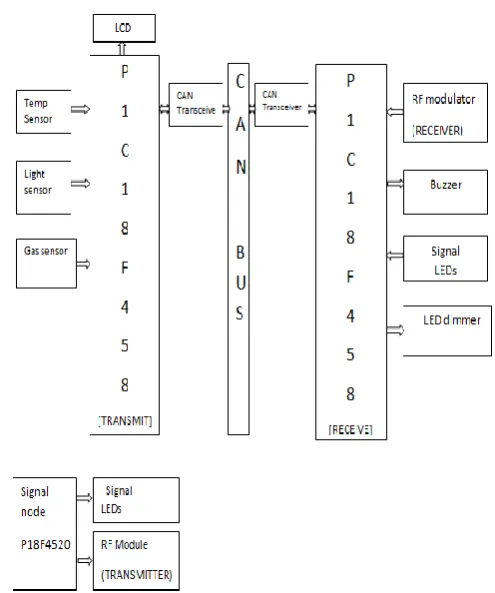
2. CONTROL SYSTEM BLOCK DIAGRAM
Fig 2: Advance Vehicle Control System
2.1 PROPOSED SYSTEM
This System consists of PIC18F458 microcontroller at both transmitting and receiving side, an additional transmitting RF module section controlled by PIC18F4520 is also added for transmitting the status of traffic lights.Transmitter is interfaced with sensors like Temperature sensor, gas leakage sensor for detecting Gas leakage, light sensor to prevent Glaring effect at transmitting side .Receiving side is interfaced with and Alert systems like Buzzer for Gas leakage, led dimmer to show effect of light sensor. Transmitter and Receiver are connected via CAN bus protocol for exchanging the information at high speed .
3. HARDWARE COMPONENTS
MICROCONTROLLER (PIC18F458, PIC18F4520)
PIC18F458 is a high performance, Enhanced flash microcontroller for embedded applications requiring a high level of integration and low power dissipation. Technical features: Connectivity-CAN2.0, I/O- 22Program Memory Size -16KB, Data Converters -A/D 5x12b, D/A 1x10b, common polynomials CRC-CCITT, CRC-16, and CRC-32. PIC18F4520 microcontroller offers high computational performance at an economical price – with high endurance, Enhanced Flash program memory. Technical features are as follows:- Master Synchronous Serial Port (MSSP) module supporting 3-wire SPI and I2C Master and slave modes , 10-bit, up to 13-channel Analog-to-Digital Converter module.
LM35
Temperature sensor used in this system is LM35, it gives an output voltage which is proportional to centigrade temperature. It is used over linear temperature sensors because the user gets the output directly in Convenient centigrade value, no need for conversion from kelvin to celsius.It works on 60µA current plus has minimal self-heating. Cost is low and operation range is from -55 to 1500C and linearity factor of +10.0mV/oC.
LDR SENSOR
LDR sensor used in this system is NSL19-MP51, it responds to the intensity of light falling on its photoconductive cells. It generates an electrical output from the light energy. The material used in Photoconductive cell is Cadmium sulphide which has same spectral curve as human. It works on the phenomenon of Photoconductivity i.e Resistance increases with falling intensity of light and decreases when intensity increases.
Fig 3: LDR Sensor
GAS SENSOR
Gas sensor used is MQ-6, used to detect gas leakage inside the vehicle .It can also detect many different types of gases like LPG, iso-butane,propane –they are flammable in nature.Detection process is very simple all we have to do is to heat the coil with 5V,add a load resistance, then connect the output to ADC. MQ-6 is defined by its high sensitivity and fast response time.
Fig 4: MQ-6 gas sensor
MCP2551 TRANSCEIVER
The MCP2551 is a high-speed, fault-tolerant device that serves as the interface between a CAN protocol controller and the physical bus. This device converts the signal received from controller to suitable format for transmission on CAN bus.It also performs the function of message management and filtering of noise from signal.
[image:2.595.46.294.120.417.2] [image:2.595.369.526.334.404.2]© 2017, IRJET | Impact Factor value: 5.181 | ISO 9001:2008 Certified Journal | Page 848
RF MODULE
This is an FSK Transceiver module, designed using the Chipcon IC. It is a true single-chip transceiver; it is based on 4 -wire digital serial interface and has integrated IF and data filter. It is defined by high performance and low cost module.It has a range of 30 meters with onboard antenna. In our system, this transreceiver is interfaced with a PIC microcontroller. It provides extensive hardware support for packet handling, data buffering, burst transmissions radio. It can be used in 2400-2483.5 MHz ISM/SRD band systems. (eg. two way Remote Keyless Entry, wireless alarm and security systems)
Fig 5: RF Module
BUZZER
A buzzer is any mechanical, electromechanical, electronic, etc. device designed to produce a buzzing sound or vibration when activated. A buzzer is in the mechanical form of a small rectangular or cylindrical housing, with electrical connection for direct mounting on rigid printed circuit.
Fig 6: Buzzer
16X2 LIQUID CRYSTAL DISLAY
LCD is the part of digital interface used to display accurate parameter values to the driver. It supports upto 16 Characters in a single row. LCDs allow displays to be much thinner than cathode ray tube technology.
Fig 7: LCD Display
4. SOFTWARE USED
DIPTRACE 2.4.0.2 - For circuit diagram and PCB Layout
MPLAB X IDE - For embedded C Programming
Flash Magic 2.4- Downloading Program to IC
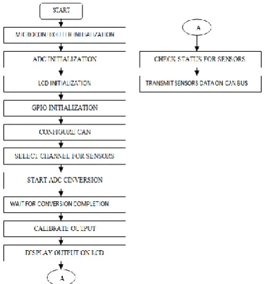
5. EMBEDDED CODE FLOW CHART
TRANSMITTER SECTION
Fig 8: Flow chart of Transmitter Section
RECEIVER SECTION
[image:3.595.363.555.237.443.2]© 2017, IRJET | Impact Factor value: 5.181 | ISO 9001:2008 Certified Journal | Page 849
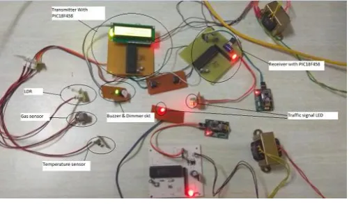
6.WORKING MODEL AND RESULTS
The fig 10 is the complete setup of Advance vehicle control system with sensors, PIC Controllers, CAN Bus, RF Module and warning system like Buzzer and Dimmer circuit and LCD to display information.
[image:4.595.309.561.117.271.2]Fig 10: Setup of Advance Vehicle control system
Figure 11 Below shows Temperature value shown on LCD
[image:4.595.37.288.184.331.2]Fig 11: Temperature changes displayed on LCD(T=38oC)
Figure 12 Below show LDR sensor value as light is flashed
Fig 12: LDR Sensor value being displayed on LCD(ldr=170Ω)
Figure 13 below Shows Gas sensor value when exposed
Fig 13: Gas Sensor value and buzzer on(LPG-216ppm)
Figure 14 below shows the transmitting and receiving function of RF module
Fig 14: Transmitter and receiver LED changes at same time
7. APPLICATIONS
Individualistic controlled vehicles:-Driver can be made more secure by using more appropriate alert systems for warning the driver before time.
Construction Machinery:-These machinaries are big and heavy and more complicated for fault monitoring, a system of sensors for monitoring the overall performance can come in handy and increases the drivers control over the vehicle.
Railway Train network:-Train networks can be connnected by using real time behaviour of CAN and the high speed and noise free transmission and integrating it with high speed microcontroller to control the vehicle .
Traffic crossing Points :-With the help of Rf module we can transmit the status of traffic lights inside the vehicle so if by any chance the traffic lights are not working properly or under maintanance , driver can be informed of traffic status.
7. CONCLUSION
[image:4.595.34.295.363.464.2] [image:4.595.37.291.495.600.2] [image:4.595.34.288.641.745.2]© 2017, IRJET | Impact Factor value: 5.181 | ISO 9001:2008 Certified Journal | Page 850
FUTURE SCOPE
This project has growth potential and can be improvised in the near future. This system can be made compulsary in every vehicle to achieve success at greater level.We can also integrate GSM, GPS, and voice module in this system to maximize the overall functioning of the system. RFID based wireless locking and unlocking system could be integrated with this system.
REFERENCES
[1] Yin Mar Win Kyaw Myo Maung Maung ,” Implementation Of CAN Based Intelligent Driver Alert System “International Journal of Scientific & Technology Research volume 5, Issue 06, JUNE 2016 .
[2] Kurunjimalar.R,” Implementation of Vehicle Monitoring System with ARM processor using Controller Area Network (CAN) Protocol “,Karpagam Journal Of Engineering Research (KJER) , Volume No.: II, Special Issue on IEEE Sponsored International Conference on Intelligent Systems and Control (ISCO’15)
[3] Jadhav Snehal Dnyandeo,”Vehicle Control System Using CAN Protocol”, International Journal of Engineering Research and General Science Volume 3, Issue 3, May-June, 2015.
[4] S. Vijayalakshmi,” Vehicle control system implementation Using CAN protocol”, International Journal of Advanced Research in Electrical, Electronics and Instrumentation Engineering,Vol. 2, Issue 6, June 2013.
[5]Vikas kumar singh “Implementation Of 'CAN' Protocol In Automobiles Using Advance Embedded System”International Journal of Engineering Trends and Technology (IJETT) – Volume 4 Issue 10- Oct 2013
[6]Selvapriya C “LPG Leakage Monitoring and Multilevel Alerting System” International Journal of Engineering Science & Research Technology, November 2013
[7] Steven F.Barrett, Daniel J. Pack, Embedded System Design and Application with the 68HC12, Pearson Education Inc., 2008
[8] http://www.microchip.com/mplab/mplab-x-ide
[9]www.computersolutions.co.uk/info/Embedded_tutorials/ can_tutorial.html
![Fig 1: CAN Bus [10]](https://thumb-us.123doks.com/thumbv2/123dok_us/8166156.807309/1.595.349.529.658.751/fig-can-bus.webp)