© 2018, IRJET | Impact Factor value: 6.171 | ISO 9001:2008 Certified Journal | Page 4260
Comparative study on effect of Earthquake on Conventional and Flat
slab building using ETABS software
Kavya M.P.M
1, Maganur D.S
2, Jagannatha G.M
31
Assistant Professor, Department of Civil Engineering, East Point College of Engineering, Bangalore, Karnataka,
India
2
Head of the Department, Department of Civil Engineering, STJ Institute of Technology, Ranebennur, Karnataka,
India
3
Professor, PG Coordinator, Department of Civil Engineering, STJ Institute of Technology, Ranebennur, Karnataka,
India
---***---Abstract - Flat slab buildings are commonly used for the
construction because use of flat slab building provides many advantages over conventional RC Frame building in terms of economical, use of space, easier formwork, architectural flexibility and importantly shorter construction time. The structural efficiency of the Flat slab construction is most difficult by its poor performance under earthquake loading. It is necessary to analyses seismic behavior of buildings for various heights to see what are the changes are going to occur for the conventional RC frame building, flat slab building with and without drops. The analysis is done with E-Tabs software. The characteristics seismic behavior of conventional RC frame building, flat slab buildings suggest that additional measures for guiding the conception and design of these structures in seismic regions are needed and to improve the performance of building having conventional RC building, flat slabs under seismic loading. The object of the present study covers the behavior of multistory buildings having conventional RC frame building, flat slabs and to study the effect of height of the building on the performance of these types of buildings under seismic forces. Present study covers information on the parameters story drift, lateral displacement, seismic base shear.
Key Words: Lateral Displacement, Storey Shear, Storey Drift, ETABS.
1. INTRODUCTION
Present days of living, all over the world the civil activities in construction going on as per demand which causes land shortage problems, Hence vertical structures is found to be an good solution. Numerous ways are there to help this plan to be successful and for speed work and budget dependent the best use is flat slab construction this technology will lowers the dead weight, and no beams will be considered, performance is good in floor area. “Flat Slab” where the technique is place the slab directly on the columns like walls. In the construction of flat slab the beams which are considered are utilized in the conventional methods are used to be new outcome the project. These constructional slabs are going to be directly resting while on the column where the load of the slab will be on the columns is going to be transferred directly and then goes to the foundation. This
project aim is to compare the normal constructional technique used in Indian with that of the modern flat slab technique and its complete analysis and all aspects considered. The software used for this project is ETABS which helps in for the analysis of comparison of all the models considered. The main technique used is the equivalent static analysis considering the code which is IS 1893. The Models of the building is completely standardized as per the demand of analysis and the major aspects considered are as Lateral displacement, story drift and the story shear and final comparisons are made.
1.1 EQUIVALENTT STATIC CO-EFFICIENT METHOD
This approach defines a series of forces acting on a building to represent the effect of earthquake ground motion, typically defined by a seismic design response spectrum. It assumes that the building responds in its fundamental mode. For this to be true, the building must be low-rise and must not twist significantly when the ground moves. The response is read from a design response spectrum, given the natural frequency of the building (either calculated or defined by the building code). The applicability of this method is extended in many building codes by applying factors to account for higher buildings with some higher modes, and for low levels of twisting.
1.2 RESPONSE SPECTRUM METHOD
The response spectrum method will be a big portion distinguished instrument methodology within the seismic research about systems. There are computational points along utilizing the response spectrum technique for seismic examination to prediction of displacements additionally part powers clinched along structural frameworks. Those approaches includes the figuring from claiming foremost the finest values of the displacements which is greater element and at each mode of vibration utilizing smooth birch outline spectra that are those normal about a few seismic tremor motions.
© 2018, IRJET | Impact Factor value: 6.171 | ISO 9001:2008 Certified Journal | Page 4261
2. METHODOLOGY
2.1 MATERIAL, FRAME AND SHELL PROPERTY CONSIDERATION
Material property
Grade of concrete: M25 and M30 Grade of steel: Fe 500
Young’s modulus of concrete: 25000 and 30000Mpa Young’s modulus of steel: 200000MPa
Unit weight of steel: 76.9729 kN/m³ Unit weight of concrete: 25 kN/m³ Frame property
Beam: (400x600)mm Column: (400x400) mm Shell property
Slab: 200 mm Wall: 230 mm
2.2 DESCRIPTION OF BUILDING WITH LOAD PARAMETERS
2.2.1 Conventional RC Building Dead Load=5 KN/
Masonry Load=19.2 KN/m Height of wall=2.4m
Live load= According IS1893-2002 Code Line load for building is 2 KN/ for terrace 1.5 KN/
Floor Finish= According to code is 1.5KN/ Masonry Load of Terrace(Parapet wall) =6 KN/m for Parapet wall top slab
No. Of Stories=G+8
2.2.2 Flat slab with Drop
Dead Load, Live load, Floor Finish are as same as that of conventional RC building system.
Drop size should not less than = ,
=5000/3=1666.66, =5000/3=1666.66
Size of the drop considered as 2000×2000˃1666.66 Drop=400mm
Slab=200mm
2.2.3 Flat slab without Drop
Load Parameters are same as Flat Slab with drop and load system as per conventional RC system.
According IS 1893-2002 code Book I=1.5, G=9.81, R=5 Formulation for scale factor = = =1471.5 scale factor
Earthquake Calculations= ˃ 85%
3. SOFTWARES USED
Extended Three Dimensional Analysis of Building Structures ETABS was used for modeling and Analysis. Auto CADD was used for preparing plan of framed structure plan.
4. MODELING
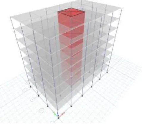
[image:2.595.312.559.195.406.2]Three models have been used.
Fig -1: 3D wireframe of conventional RC structure
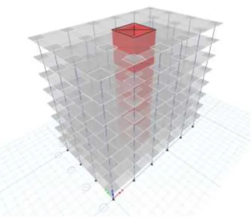
[image:2.595.314.553.453.660.2]© 2018, IRJET | Impact Factor value: 6.171 | ISO 9001:2008 Certified Journal | Page 4262 Fig -3: 3D wireframe of Flat Slab with drop structure
5. RESULTS
5.1 CONVENTIONAL RC STRUCTURE
Fig -4: Maximum Story Displacement
Story Elevation X-Dir Y-Dir
m mm mm
Story8 24.45 0.013 0.021
Story7 21.45 0.012 0.021
Story6 18.45 0.012 0.02
Story5 15.45 0.011 0.018
Story4 12.45 0.009 0.015
Story3 9.45 0.007 0.012
Story2 6.45 0.005 0.008
Story1 3.45 0.003 0.004
Pstory 0.45 1.706E-04 2.706E-04
Base 0 0 0
[image:3.595.305.558.113.303.2]Table -1: Tabulated Plot Coordinates Story Displacement Values
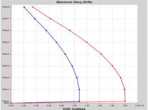
[image:3.595.308.558.336.525.2]Fig -5: Maximum Story Drift
Fig -6: Maximum Story Shears
5.2 FLAT SLAB WITHOUT DROP STRUCTURE
[image:3.595.36.285.383.570.2]© 2018, IRJET | Impact Factor value: 6.171 | ISO 9001:2008 Certified Journal | Page 4263 Story Elevation X-Dir Y-Dir
m mm mm
Story8 24.45 0.018 0.03
Story7 21.45 0.017 0.029
Story6 18.45 0.016 0.027
Story5 15.45 0.014 0.024
Story4 12.45 0.012 0.021
Story3 9.45 0.01 0.016
Story2 6.45 0.007 0.011
Story1 3.45 0.004 0.006
Pstory 0.45 4.867E-04 0.001
[image:4.595.307.559.102.292.2]Base 0 0 0
Table -2: Tabulated Plot Coordinates Story Displacement Values
Fig -8: Maximum Story Drift
Fig -9: Maximum Story Shear
[image:4.595.35.283.287.472.2]5.3 FLAT SLAB WITH DROP STRUCTURE
Fig -10: Maximum Story Displacement
Story Elevation X-Dir Y-Dir
M mm mm
Story8 24.45 0.018 0.029
Story7 21.45 0.018 0.028
Story6 18.45 0.016 0.026
Story5 15.45 0.015 0.023
Story4 12.45 0.012 0.02
Story3 9.45 0.01 0.015
Story2 6.45 0.007 0.011
Story1 3.45 0.003 0.005
Pstory 0.45 1.48E-04 1.956E-04
[image:4.595.292.557.519.708.2]Base 0 0 0
Table -3: Tabulated Plot Coordinates Story Displacement Values
© 2018, IRJET | Impact Factor value: 6.171 | ISO 9001:2008 Certified Journal | Page 4264 Fig -12: Maximum Story Shear
6. RESULTS AND COMPARISON
X Direction
Conventional
RC structure Flat slab without drop
Flat slab with drop
Displacement 0.072171 0.098487 0.09915
Drift 6.14E-06 7.58E-06 6.90E-06
[image:5.595.304.561.77.268.2]Shear 144997.5 82113.36 89003.5
Table -4: Results and Comparison values
[image:5.595.307.559.302.490.2]Fig -13: Displacement values
Fig -14: Story Drift values
Fig -15: Story Shear values
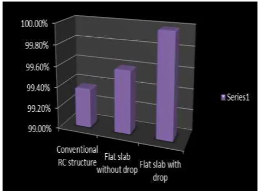
[image:5.595.38.286.444.634.2] [image:5.595.306.559.522.709.2]© 2018, IRJET | Impact Factor value: 6.171 | ISO 9001:2008 Certified Journal | Page 4265 Conventional RC
structure Flat slab without drop Flat slab with drop
99.375% 99.60% 99.99%
Table -5: Response Spectrum Analysis
6. CONCLUSIONS
The following conclusions can be drawn from the analysis.
The conventional RC frame structure gives more resistance to earthquake.
The displacement in the Flat slab with and without drop structure is more as compared with Conventional RC Frame structure.
The Story Drift in the Flat slab with and without drop structure is more as compared with Conventional RC Frame structure.
The Base Shear in the Flat slab with and without drop structure is less as compared with Conventional RC Frame structure.
Hence from all the observation made, it is clear that the conventional RC structure will be suitable as compared with flat slab with drop and flat slab without drop structure.ACKNOWLEDGEMENTS
Authors would like to thank the Department of Civil Engineering, Sri Taralabalu Jagadguru Institute of Technology, Ranebennur for supporting our work.
REFERENCES
(1) Mrs.Sumitpahwa, “Study of the comparison of the flat slab in one or two way”.
(2) Ms. Navyashree K and SahanaInternational, “Analysis of flat slab using the conventional method at different seismic zones”.
(3) Dr. Uttamashagupta, “Seismic behavior of buildings having flat slabs with drops”. International Journal of Emerging Technology and Advanced Engineering website: www.ijetae.com (ISSN 2250-2459, volume 2, issue 10, October 2012).
(4) IS: 875 – 1987 - code of practice for design loads (other than earthquake) for buildings and structures, part 1: Dead loads, part 2: Imposed loads, part 5: Special loads and load combinations, bureau of Indian standards, New Delhi.
(5) IS: 1893 (part–1)–2002 - code of practice for criteria for earthquake resistant design of structures, part 1: general provisions and buildings, bureau of Indian standards, New Delhi.
(6) IS:456-2000-code of practice for plain and reinforced concrete, fourth revision.
(8) Pradip S. Landel, Aniket B. Raut Associate Professor Government College of Engineering, Amravati Maharashtra, India, “Seismic Behaviour of Flat Slab Systems”.
(9) DhananjayD.Structural Engineering Department, Govt. College of Engineering Aurangabad, “Performance of Flat Slab Structure Using Pushover Analysis”.