279
PRODUCT DESIGN METHODOLOGY FOR MODELING
MULTI BUSINESS PRODUCTS: COMPARATIVE STUDY
BETWEEN UML AND BPMN MODELING FOR BUSINESS
PROCESSES
1
KNOUNI SALMA, 2BENHIDA KHALID, 3EL FEZAZI SAID
1
Phd Student, ERGI Team, EST Safi, UCA, Morocco
2,3
ERGI Team, EST Safi, UCA, Morocco
E-mail: [email protected], [email protected] , [email protected]
ABSTRACT
The development of a multidisciplinary product (having a strong software component) is a complex task with multiple constraints, especially during the design phase. The mastery of the design phase is a necessary condition for the product development success and therefore assuring its competitiveness on the market. To contribute to this mastery, the formalization and modeling of the process design is imperative. We aim in this article, the formalization of multidisciplinary product’s design methodology with an organizational character, throughout the modeling of the product design process’s different aspects: structural, behavioral ..., which can be exploited by business stakeholders or software analysts. We used two modeling standards: UML and BPMN and we made a comparative study between models obtained by these two standards
Keywords: Design, multidisciplinary product, process modeling, UML, BPMN.
1. INTRODUCTION
The design phase is one of the crucial steps in the development of any product. Several researches focus on solving conceptual technical problems; others target the organizational aspect depending on the human factor and the profiles of the design process and product development participant.
In order to standardize these processes and for the different profiles (business, software) to be able to work with them, several modeling standards have been implemented, each focusing on a specific aspect among which we find UML [1, 2] and BPMN [3,4] two of the most widely used standard for modeling software projects and business processes.
In this paper, we will first locate the design phase in the life cycle of a product, introduce afterwards the design methodology which we are going to model in the third section, then compare in the fourth section, the models of the two modeling standards, in order to deduce the formalization of a final model that can be used for similar processes.
vice have been considered. The multi-layer feed-forward ANN toolbox of MATLAB 6.5 with the error back-propagation training method is employed.
2. MULTI TRADE PRODUCT DESIGN
Before we begin presenting or modeling our multi-trade product’s design methodology, we have to relocate it, in a more global and general framework of the life cycle of the project to which it belongs.
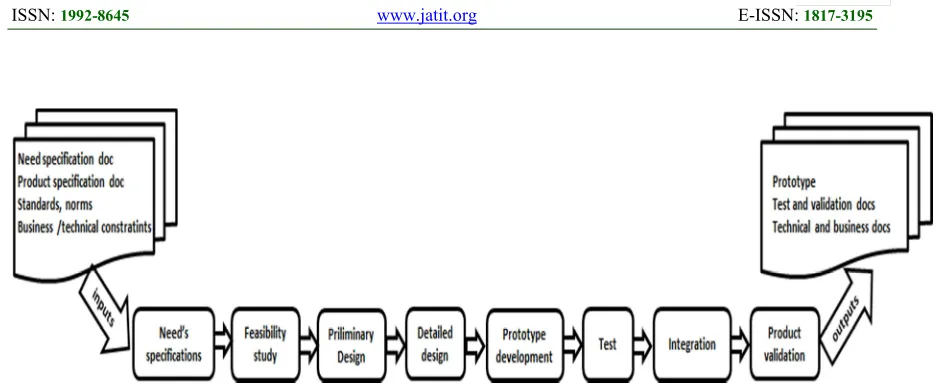
1.1. Product Design Phase
In the case of this study, we consider the design phase in its general aspect: which concerns every process related to the need's specification, feasibility study, preliminary and detailed design, prototype realization and even the test, integration and validation steps. The product lifecycle on the other hand contains, in addition to the different steps mentioned earlier, the production, commercialization and other market or product related steps.
The particularity of our study lays in the fact that the products considered are multidisciplinary products, requiring the collaboration and cooperation of many disciplines in order to pass a successful design phase.
280
1.2. Organizational aspects of multi trades
product’s design process
Several methods and theories deal with the issues related to product design. These techniques can be grouped into three major approaches: Classic [5, 6], systemic [7, 8] and innovative [9, 10].
These methods are mainly interested in the technical aspects related to the design of a new product. The organizational aspect, which influences strongly the design phase’s success especially for multidisciplinary products, is still rarely addressed by these techniques. In this study, we develop a modeling methodology [11, 12] that considers mainly the organizational side related to the design phase of these products, particularly through development project framework.
This method was based on a company specializing in multidisciplinary products’ design, incorporating three main components: electronic, mechanical and software. This methodology relies on the setting of a product Marketing department MKTP, in order to have a better control over the product's specification step, the use of a project organization as to improve different trades and businesses coordination, and the establishment of a project committee responsible for the control, review and supervision of all product design steps.
Indeed, the existence of a product Marketing entity becomes crucial as it helps achieving a better definition and specification of the market's needs (and therefor client's needs and specifications), as well as it intervenes during the new products feasibility study. Further, it plays an important role in the supervision and overall project control.
The adoption of a cooperative project organization on the other hand, allows a good communication between the several intervening departments during the design and product implementation steps. It also reduces / decreases the potential for errors during the integration of the different product components. Thus, for each new product's design and development stages an independent project team is assigned. Team members come from all product related business department (ensuring thereby a good business coordination), and are supervised by a project manager.
The project team adopts a per part development, as each product is composed of several articles (each one of them related to a specific business or trade), and each article is composed of several
interfaces. The design implementation of each article is assigned to a responsible team member "Article Development Responsible" who will be in charge of the accomplishment of the different design steps related to all interfaces of his assigned article.
A project committee is assigned to each new product as well. This committee is in charge of the control and supervision of the project team's work. Its members come from: quality, production and product marketing departments, they ensure the validation of the design phase's steps (particularly the articles design steps).Thus, the transit from a design step to another will not be possible unless the previous step is thoroughly verified and validated.
3. MODELING OF MULTI BUSINESS
PRODUCT’S DESIGN PHASE
In this section, we propose a modeling for the design methodology described in the previous section. We’ve opted for the UML and BPMN standards modeling languages, to ensure that we describe all the aspects of the methodology and obtain comprehensible and standards models that can be easily interpreted and reused.
3.1. UML Modeling
Unified Modeling Language UML, is a visual and graphical language for the modeling, specification design and documentation of object oriented systems [1,2,13] which became increasingly the design standard for software engineering and development area, throughout the last decade.
Created and standardized by the Object Management Group OMG, UML can also be used for non-software development and information system design purposes. Indeed, UML can be used in processes requirement gathering, and it is considered as a major tool of business process management [14] as it is used during the process definition and analysis phase [13,14].
One of the strong characteristics of UML is that it is a methodology independent modeling standard: regardless of the analysis and design processes, we can express our results using UML diagrams.
In this paper we opted for UML 2.0, which defines thirteen types of diagrams within three major categories:
281 Behavior diagrams: describing the general types of system behavior
Interaction diagrams: representing different aspects of system’s interactions.
We will focus in this section on the behavior aspect of our design phase: described in the use case diagram as well as the activity diagram, and on the structural or static aspect described in the class diagram.
3.1.1.Modeling the behavior aspect with use
case diagram
The use case diagrams describe aspects of software systems’ behavior, or in our case, the process being modeled, focusing on the roles assigned to its participants called "actors" and their respective functions known use cases [1,2,13].
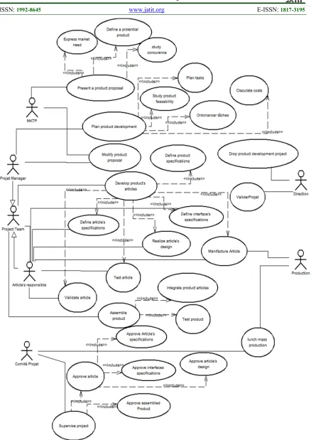
Figure 2 shows the use case diagram corresponding to our new product’s design methodology. The diagram shows the various actors involved in our design phase and specifies their functions, which vary as described in the presentation of the methodology section. We can group all our players in three main categories:
Departments of the company: such as MKTP department, responsible for the proposal of new products for which it expresses the need of the market, considering the competition and defining the potential product to offer. This department is also responsible for making product changes when needed in collaboration with the project manager.
The Direction department: is responsible for the validation or discontinuation of the product.
The Production department: it collaborates during the article prototype manufacturing as well as during the mass production of the final product.
The teams: such as the project development team responsible for product’s items’ development and assembly.
The project committee: responsible for the validation of each article in collaboration with the member in charge of the article, and works with the production in the mass production of the product. It oversees the project and must approve the specifications of each article, its interfaces, as well as its design specifications in order to approve the article and therefore the assembled product.
Members of teams such as the project team leaders cooperating with MKTP department in the change of the product proposal when in need. They
are also responsible for product development planning which includes product’s feasibility and cost study, planning and scheduling tasks as well as the validation of product’s items.
Product’s items’ development responsible is in charge of the different phases of design and development of an article, since the definition of its specifications and its interfaces till the manufacturing of the article in collaboration with the production, as well as the product testing and validation under the supervision of the project committee.
3.1.2.Modeling the behavioral aspect with the
activity diagram
The activity diagram describes the behavior of systems and processes by presenting their flow at system level as well as at business level by describing the actions’ succession of a system [1,2,13] (or in our case of a process) known as activities while taking the triggers, inputs and outputs of these activities into consideration.
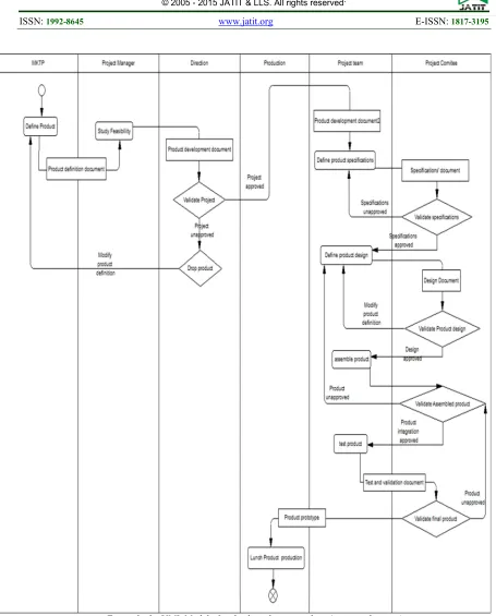
Figure 3 shows the generic activity diagram of our design methodology for new multi-business products. The diagram indicates that the design process starts with the activity of the expression of market needs conducted by the MKTP Department, and ends with the mass production of the final product. Between these two activities comes a set of activities composing the design process of a new product as previously defined in the use case diagram (Figure 1), rules conditioning the activities’ succession are pointed out if necessary. For example, we can’t move on to defining the specifications of the product unless the proposed product development project is validated and approved by management. Otherwise, we proceed to the validation of the proposed product itself in order to clarify whether there would be a change in its definition, or the product design project will be abandoned.
282 for each product item. It also details the work of the project team, including the tasks given to the members in charge of each article, the manager and the project committee as well as the contribution of the production department while specifying the input and the output documents for each step.
3.1.3.Modeling of the static structure with the
class diagram
The class diagram describes the static structure focusing on entities (called classes) regardless of the time component. It also outlines the relationships between entities ranging from composition, inheritance or simple associations [1,2,13].
Figure 5 presents the class diagram corresponding to our design phase process. The diagram shows us that the team members who consists the project team can be employees of the company’s business services or employees of an external collaborating firm. This is not the case of the project committee members, since the committee is consisted strictly from employees of the different company’s departments. And despite the fact that committee members may belong to several project committees (and hence may be involved in several product development projects) at a time, each Project Committee can oversee the development of a single product. This is also the case of project teams and their members; they can only be in charge of a single product development project at a time.
The product is composed of numerous articles or items and each article itself is composed of several interfaces developed strictly by a specific member of the team "item development responsible". Each interface, and therefore each item and product, has a set of specification, design, testing and validation documents.
4. BPM MODELING
Business process modeling notation: BPMN is one of the latest standards for graphical modeling of business processes. Developed and published by the BPMI in 2004; BPMN has gained wide acceptance among the business and IT analysts, as one of its main objectives was to bridge the gap between process modeling and software implementation [4.15].
Another primary goal of BPMN is to provide an understandable notation to all professional users: including business analysts responsible for the
initial process drafting, technical and IT developers in charge of the software process implementation, as well as managers and professional end-users [3,4,14].
BPMN modeling is based on the flow charting technique [16,17], it graphically represents the business process models “BPM” using business process diagrams “BPD”.
A BPD is a set of graphical objects [3,4,14,17,18,19]: activities and tasks (representing the shares of the business process) ordered by flow controllers (interactions and associations between the paths leading to the activities that have to be followed throughout the process cycle) ,the decisions are represented by gateways. Activities are organized in pools (graphical representation of the process’s organizational entities) that can be s into multiple sub parted into multiple swimlanes, if a pool (therefor an organizational entity) includes more than one participant or role. [3,4,14], .
There are two basic types of patterns that can be created by a BPD. Collaboration Models (or public) representing the interactions between one or more other organizational entities. And internal models (or private) focusing on the interactions and internal activities of a single organizational entity [3,4,14].
In our study, we focus on the product design process in one company, without having to handle interactions with other external entities, which makes our BPD represents an internal BPM which details the design process of a new company’s product.
Figure 6 shows the BPD representing the new product design process of our methodology. This diagram shows the same process described by the activity diagram in Figure 4 with more business oriented notations and BPMN specifications. The diagram uses a single pool to represent the company contains as many swimlanes as the number of actors’ functions and roles involved in the process and already listed in the previous sections. Activities are organized in each swimlane according to the role responsible role for the fulfillment of each one of them.
283 of article’s integration’s approval is verified (or validation’s approval).
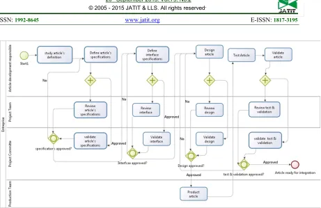
Figure 7 shows the details of the product development sub-process [3, 4, 14, 16, 17, 18, 19] (which is one of BPD actions of Figure 8), the diagram also uses a single pool to represent the company and partitions activities in swimlanes representing their respective roles. In this diagram, we use two types of gateways:
Parallel Gateway: which in our case divides the input sequence flow into two output sequence flows, thus the definition of item’s specifications (for example) creates two parallel actions leaded by two different actors: the verification of Article’s specifications leaded by the project team and the validation of specifications leaded by the project committee.
The second type, inclusive gateway help gather multiple input streams in order to choose only one sequence flow (output) that will be followed according to a condition. For example, in our case after the end of the two stages of interface’s specifications validation and verification, we do not carry on to the item’s design step unless the interface is approved. If this condition is not verified we go back to the interface’s definition step: our process can only follow one of these two paths depending on the result of the condition of the gateway.
5. COMPARING UML AND BPMN
MODELING
In order to formalize the steps of a multi-disciplinary product design process, we studied two graphical representations: UML and BPM. These two representations are currently the two most used graphical for process modeling. These models show that UML AD (activity diagram) presents a set of advantages: It supports sending and receiving signals at a conceptual level, it supports call waiting and the statements and provides treatment a transparent mechanism to decompose a multiple active in activities. The work of Dumas, Hofstede and Russel [20,21] confirms these assets. However, although the activity diagram provides full flow control support, it is limited in terms of modeling resources related to a process and to its organizational aspects [21,22]. Indeed, business analysts cannot express, using this diagram, the different levels of granularity of a business process and its interactions in its operating environment. This is mainly due to the fact that the diagram originally targeted software development despite its
updated UML 2.0 updates. On the other hand, the use of activity diagram for business process modeling by business analysts is not always obvious, a technical knowledge of UML and in particular UML AD is required. In addition, the activity diagram also lacks precision in syntax and semantics. It is present, for example, in modeling decision branches [21,22]: the rules connecting its branches with their corresponding flows are not fully determined and the types of synchronization such as discriminators are not fully taken into account.
As for the BPM modeling, we can say that one of the main strengths of this representation is it being compatible with most flowcharting notations while providing more flow controllers. It can model different types of processes [4,14,15]: private or internal, public or abstract, global or collaboration with different levels of granularity [4,14,23]: roles can be defined at different business process levels through pools and swimlanes unlike the UML AD [4,14,15,19,22,23] This is due to the fact that BPMN was essentially made for business analysts, and contains only one diagram properly detailed and dedicated to business process modeling only. Another advantage of BPMN is its ability to be mapped into the execution code, which may not seem very interesting in our case of study, but will have a great impact in the adaptation and automation of a business process within an enterprise [4,19,24].
6. CONCLUSION
The design methodology modeled in this article is the standardization of the design process of multi trade product’s having a strong software component. UML modeling therefore may seem more appropriate for the study of the design and development of this component. However, the multidisciplinary aspect of the product as well as UML AD gaps in term of business process modeling, described in the paragraph comparing UML and BPMN modeling, favors, when it comes to business process modeling, the adoption of BPMN models which detail business processes with a high level of granularity, and addresses at the same time the different profiles involved in the design process studied.
284 organizational hierarchy of the participants as well as product decomposition.
We believe that the models developed in the context of this article can be a formal framework that can be exploited for the design of multi trade products.
REFRENCES:
[1] G. Booch, J. Rumbaugh, I. Jacobson, “The Unified Modeling Language User Guide”, Addison Wesley, 1999.
[2] J et D. Gabay . UML 2 Analyse et conception ». Dunod 2008
[3] “ BPMN: An introduction to the standard” Michele Chinosi , Alberto Trombetta, Computer Standards & Interfaces , 34 (2012) , pp.124–134 elsevier
[4] “OMG, Business process model and notation (BPMN 2.0)”, formal/2011-01-03,OMG, http://www.omg.org/spec/BPMN/2.0 (May 2011)
[5] Chan, M-L. Wu (2002) ‘’Quality function deployment : A literature review’’. European of Operational Research, 143, (3),463-497. [6] R. Tassinari ‘’Pratique de l'analyse
fonctionnelle’’, Dunod Paris 1997
[7] Nam P. Suh ‘’The Principles of Axiomatic Design’’, 1990
[8] Hassan, A. Siadat, J.Y Dantan, P. Martin ‘’Utilisation de l’AMDEC comme outil de formalisation des connaissances pour la gestion de la qualité en conception et industrialisation’’. C2EI, 2007, Belfort, France
[9] A.Hatchuel et B.Weil, ‘’La théorie C-K : Fondements et usages d’une théorie unifiée de la conception, Colloque Sciences de la conception’’ 2002
[10] Horowitz R., ASIT, Méthode pour des solutions innovantes Solidcreativity, 2003 [11] K. Benhida et al. Mise en place d’une
méthodologie de développement pour la maîtrise des phases étude et conception produit, CPI, 2005, Casablanca, Maroc
[12] K. Benhida et al. Méthodologie collaborative de développement produit-Maîtrise de la phase de spécification, CPI, 2007, EMI-Rabat-Maroc [13] OMG (2004 b), UML 2.0 Superstructure
Specification, OMG, Needham, MA, available at http://www.omg.org/spec/UML/2.0/
[14] Mathias Weske Business Process Management Concepts, Languages, Architectures © Springer-Verlag Berlin Heidelberg 2007
[15] K.L.KO Ryan, S.G.Lee Stephen, Eng Wah Lee, Business Process Management (BPM) Standards: a survey, Business Process Management Journal, Vol 15, No 5, 2009, pp. 774-7791 Emrald group publishing.
[16]W.M.P. van der Aalst, A.H.M. ter Hofstede, B. Kiepuszewski, A.P. Barros, Workflow patterns, Distributed and Parallel Databases 14 (2003) 5– 51
[17] S.A. White, Process modeling notations and workflow patterns, in: L. Fischer (Ed.), Workflow Handbook 2004, Future Strategies Inc., Lighthouse Point, FL, USA, 2004,pp. 115– 126
[18] S. A.White , IBM corporation Introduction to BPMN white paper
[19] OMG (2008 c), OMG Business Modeling Specifications, OMG, Needham, MA, available at www.bpmn.org/
[20] OMG (2004 a), Business Process Modeling Notation (BPMN), OMG, Needham, MA, available at www.bpmn.org/
[21] M. Dumas and Arthur H.M. ter Hofstede (2001),UML Activity Diagramsas a Workflow Specification Language, UML 2001: 4th international conference on the Unified Modeling Language: Modeling Languages, Concepts and tools, Toronto, pp.76-90.
[22]N. Russell, W. M.P van der Aalst, Ter Hofstede, A.H.M and P. Wohed (2006) “On the suitability of UML 2.0 activity diagrams for business process modelling, Proceedings of the 3rd Asia-Pacific conference on Conceptual modeling, vol 53, pp 95-104
[23]P.Wohed, W.MP van der Aalst, M. Dumas, ter Hofstede, N. Russell Pattern-based analysis of the control-flow perspective of UML activity diagrams, Conceptual Modeling–ER 2005 ,Springer Berlin Heidelberg, pp 63-78
[24]P Wohed, WMP van der Aalst, M Dumas, AHM ter Hofstede, N Russell (2006) On the suitability of BPMN for business process modelling , Business Process Management, 161-176
[image:7.612.85.556.74.270.2]
285
[image:8.612.92.530.68.687.2]
286
Figure 2: The UML Model Of Multi-Disciplinary Products( Use Case Diagram)
[image:9.612.73.528.62.627.2]
287
288
289
Figure 5: the UML Model of multi-disciplinary product : class diagram
[image:12.612.94.555.53.352.2]
290