AN ECONOMIC APPROACH TO SPEED REGULATION OF
INDUCTION MOTOR USING SUPER LIFT LUO CONVERTER
1 P.ELANGOVAN, 2 Dr.C .KUMAR, 3 B .GOMATHY
1
Assistant Professor, Department of EEE, S.K.P. Engineering College, Tiruvannamalai, India
2
Academic Director, S.K.P. Engineering College, Tiruvannamalai, India
3
PG Student, Department of EEE, S.K.P. Engineering College, Tiruvannamalai, India
E-mail: [email protected], [email protected], [email protected]
ABSTRACT
This paper proposes an economic approach for the speed control of Induction motor using positive output super lift Luo converter circuit. In the conventional method, the input of the inverter is derived from buck, boost or buck-boost converter which has the limitations over the DC link voltage level, complexity of control circuit and cost involved in system design. The proposed method uses positive output super lift Luo converter at the front end which boosts up the DC link voltage level in a wide range. The speed control of the induction motor is attained by controlling the firing angle of positive output super lift Luo converter instead of Inverter which leads to prevention of motor terminals from Common mode voltage stress. Super-lift Luo-converters are popular for high output voltage application over years. They have very high voltage transfer gains in geometric progression on stage-by-stage. The proposed system uses PI controller which is highly preferable for industrial applications. The simulation is conceded out by MATLAB/SIMULINK software.
Keywords: Induction motor, PI controller, Positive Output Elementary Super-Lift Luo Converter, Speed
Regulation, Voltage Source Inverter
1. INTRODUCTION
Sensorless control of induction motor drives shows recent development for high performance industrial application [1]. Such control trims down cost of the drive, size, and maintenance requirements by holding good system reliability and robustness. However, parameter sensitivity, high computational effort, and stability at low and zero speeds can be the main shortcomings of sensorless control. Much recent research effort is focused on extending the operating region of sensorless drives near zero stator frequency [2], [3]. Several solutions for sensorless regulation of induction motor drives have been anticipated based on the machine elementary excitation model and methods on high frequency signal injection, as recapitulated recently [1]. Fundamental model-based strategies use the instant values of stator voltages and currents to approximate the flux linkage and speed of the motor. Model reference adaptive system, Luenberger and Kalman-filter observers, sliding-mode observers, and artificial intelligence techniques have been suggested. Model
reference adaptive system scheme offers simpler execution and require less calculational effort compared to other methods and are therefore the most popular tactics applied for sensorless control [3], [4].
However, the methods used in the literature [1] – [4] uses the feedback signal to control the gating pulses of Voltage Source Inverter (VSI), it results in complex control circuit design. In VSI both voltage and frequency at the output are varied to achieve speed control under v/f control to maintain high torque capability at all frequencies. The ratio v/f is chosen corresponding to the rated voltage and frequency. In PWM inverters, amplitude of fundamental output voltage is directly proportional to the modulation index 'm' [5]. The modulation index value is varied to control the width of the gate pulse.
converters can be changed by changing the duty cycle. The positive output elementary super lift Luo converter is a new series of DC-DC converters possessing high-voltage transfer gain, high power density; high efficiency, reduced ripple voltage and current [6]. These converters are widely used in computer peripheral equipment, industrial applications and switch mode power supply, especially for high voltage-voltage projects [6]-[7]. Control for them needs to be studied for the future application of these good topologies.
The super-lift technique considerably increases the voltage transfer gain stage by stage in geometric progression [8]-[9]. However, their circuits are complex. An approach, positive output elementary super lift Luo converters, that implements the output voltage increasing in geometric progression with a simple structured have been introduced. These converters also effectively enhance the voltage transfer gain in power-law terms [6].
Due to the time variations and switching nature of the power converters, their static and dynamic behavior becomes highly non-linear. The design of high performance control for them is a challenge for both the control engineering engineers and power electronics engineers. In general, a good control for DC-DC converters always ensures stability in arbitrary operating condition. Moreover, good response in terms of rejection of load variations, input voltage variations and even parameter uncertainties is also required for a typical control scheme. The static and dynamic characteristics of these converters have been well discussed in the literature [10].
The PI control technique offers several advantages compared to PID control methods and they are stability, even for large line and load variations, reduce the steady error, robustness, good dynamic response and simple implementation.
In this paper, state-space model for Positive output elementary Super- lift Luo converter are derived at first. A PI control is designed to control the gate signal of Positive output elementary Super- lift Luo converter with the help of induction motor reference speed. The performance of the system with PI control for positive output elementary super lift Luo converter is studied in Matlab/Simulink. Details on operation, analysis, control strategy and simulation results for Positive output elementary super lift Luo converter - VSI controlled Induction motor are presented in the subsequent sections.
2. MATHEMATICAL MODELLING OF
THREE PHASE INDUCTION MOTOR
[image:2.595.311.508.239.337.2]The mathematical model of the plant is highly required to design any type of controller for the purpose of process control. The mathematical modeling of induction motor and the power circuit of 3-φ voltage source inverter which feeds the induction motor is shown in the Figure 1.
Figure 1: Power circuit of induction motor
The equivalent circuit used for obtaining the mathematical model of the induction motor is shown in the Figure 2.
(a) d-axis
(b) q-axis
Figure 2: Equivalent circuit of induction motor in d-q frame
[image:2.595.310.517.410.660.2]calculated voltage is then synthesized using the space vector modulation:
V1d = R1i1d +
λ1d – ωdλ1q (1)
V1q=R1i1q+
1q – d1d (2)
V2d=R2i2d +
2d - d2q (3)
V2q=R2i2q +
2q - d2d (4)
V
1d and V1q, V2d and V2q are the direct axes and
quadrature axes stator and rotor voltages. For justification, the stator side parameters are used with suffix 1 and rotor side parameters are used with suffix 2. The flux linkages to the currents are given by the Eq. (5):
λλ λ λ = M ii i i (5)
Where M =
L 0 L 0
0 L 0 L
L 0 L 0
0 L 0 L
The electrical part of an induction motor can thus be described, by combining the above equations we get Eq. (6):
ii i i = మ
ౣ మ భ
A ii i i
L 0 L 0
0 L 0 L
L 0 L 0
0 L 0 L
V V V V (6)
where, A is given by:
A =
a a a a
a a a a
a a a a
a a a a
(7)
and
a = LR
a = ωL ωLL
a = LR
a = LL ω ω
a = ωL ωLL
a = LR
a = LL ω ω
a = LR
a = LR
a = LL ω ω
a = LR
a = ωL ωLL
a = LLω ω
a = LR
a = ωL ωLL
a = LR
The instantaneous torque produced is given by:
Tem =
(λ2qi2d – λ2di2q) (8)
The electromagnetic torque expressed in terms of inductances is given by:
em
Lmi1q 2di1q 2q (9)
The mechanical part of the motor is modeled by the equation:
ωMech =
ౣ ై
౧
=
ౌ
మ ౣభ౧మౚ భౚమ౧ ై
౧ (10)
3. POSITIVE OUTPUT ELEMENTARY
SUPER-LIFT LUO CONVERTER
For the function of optimize the stability of positive output elementary super lift Luo converter dynamics, while ensuring correct operation in any working condition, a PI control is a more practicable approach.
The PI control has been presented as a good substitute to the control of switching power converters [11]. The main benefit of PI control scheme is its insusceptibility to plant/system parameter variation that leads to invariant dynamics and static response in the ideal case.
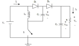
Figure 3 shows the positive output elementary super lift Luo converter. It consist of dc supply voltage Vi, capacitors C1and C2 , inductor
L1, power switch (n-channel MOSFET) S,
freewheeling diodes D1and D2and load resistance
[image:4.595.107.273.197.295.2]R.
Figure 3: The positive output elementary super lift Luo converter
The principle of the sliding mode controller is to make the capacitor voltages VC1and
VC2 follow as faithfully as possible capacitor
[image:4.595.95.287.426.517.2]voltage references. It is assumed that all the components are ideal and also the positive output elementary super lift Luo converter operates in a continuous conduction mode. Figure 4 shows the mode of operation during switch S is on.
[image:4.595.298.516.507.582.2]Figure 4: Mode of operation during Switch ON
Figure 5 shows the mode of operation during switch S is off.
Figure 5: Mode of operation during Switch OFF
In Fig. 4 when the switch S is closed, voltage across capacitor C1is charged to Vi. The
current iL1flowing through inductor L1 increases
with voltage Vi. In Fig. 5 when the switch S is
closed, decreases with voltage (Vo - 2 Vi).
The output voltage (Vo) of Positive Output
Super-lift Luo converter is
Vo =
Vi (11)
Here, δ is the duty cycle and the range of it is 0 < δ < 2 and δ ≠ 1.
The VSI used in the proposed system operates under 180° mode and the firing angle of it will not be disturbed because the scalar control of induction motor needs change in supply voltage instead frequency.
The r.m.s. value of the line output voltage of VSI is
VL = 0.8165VS (12)
In the projected system, VS
(source voltage of VSI) is the output voltage of Positive Output Elementary Super-lift Luo converter Vo. Therefore,
VL = 0.8165(
)Vi (13)
The line voltage supply for the three phase induction motor and the corresponding input voltage utilized at DC/DC converter end with respect to the duty cycle is tabulated and is shown in Table 1.
Table 1: Source and Load Voltage of Proposed System
Duty Cycle δ Input DC Voltage Output AC line Voltage
0.9 46.76 V 420 V
0.8 85.73 V 420 V
0.7 119.62 V 420 V
0.6 146.96 V 420 V
0.5 171.46 V 420 V
4. PI CONTROLLER DESIGN FOR THE
PROPOSED SYSTEM
[image:4.595.92.281.530.691.2]step response of Positive output elementary super lift Luo converter and delay time L = 0.005s and time constant T = 0.052s has been characterized.
Ziegler and Nichols suggested to set the values of Kp = 9.36 and Ti = 0.016s.
5. SIMULATION
The validation of proposed system
performance has been done using
[image:5.595.302.517.76.271.2]MATLAB/Simulink package with the parameter listed in Table-2.
Table 2 : Parameters of Proposed System
Parameter Rating
Source Voltage 60V, DC
C1 20µF
C2 1000µF
L1 0.5mH
Inverter Switches IGBT
Induction Motor 5HP, (430V-460V) AC, 60Hz, 1750RPM
[image:5.595.309.508.376.504.2]The MATLAB/Simulink model for the proposed Positive output Super-lift luo converter is shown in Figure 6. The simulink model for Positive output Super-lift luo converter shows the simplicity in the design and the number of switches used is only one. Figure 7 shows the Input and Output Voltage of Positive output Super-lift Luo Converter. From the simulation result, it is very clear that for the given 60V DC, the proposed Positive output Super-lift Luo Converter produces the output voltage of 430V DC which shows that to drive a three phase Induction motor a minimum source can be utilized.
Figure 6: Simulink model of Positive output Super-lift Luo Converter
Figure 7: Input and Output Voltage of Positive Output Super-lift Luo Converter
The stator current of three phase induction motor is depicted in Figure 8. It can be seen that the high inrush current to the motor terminal has been vanished out within 0.5 seconds which adds one more advantage for the proposed system.
Figure 8: Stator Current of Three phase Induction Motor
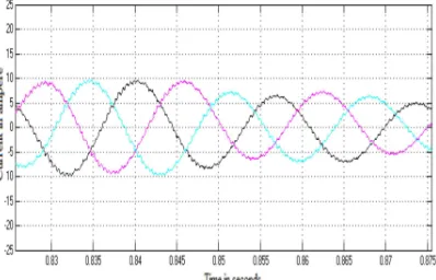
[image:5.595.90.292.490.692.2]The line voltage at the stator terminals of three phase induction motor is shown in Figure 9. Highly eliminated voltage stress which is the root cause of bearing current is very clear from Figure 9 and it adds the major advantage on the proposed system.
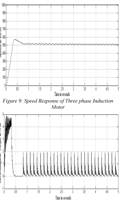
[image:5.595.308.508.610.717.2]Figure 10 and Figure 11 shows the speed response and the electromagnetic torque of three phase induction motor. The reference speed assigned to the three phase induction motor is 500 rpm. The motor speed has been regulated within a second.
Figure 9: Speed Response of Three phase Induction Motor
Figure 10: Electromagnetic Torque
6. CONCLUSION
The positive output elementary super lift Luo converter performs the voltage conversion from positive source voltage to positive load voltage. Due to the time variations and switching nature of the power converters, their dynamic behavior of the three phase induction motor becomes highly non-linear. This paper has successfully demonstrated the simple system design and suitability of PI controlled positive output elementary super lift Luo converter for speed regulation system of three phase induction motor. The result shows that with minimum DC voltage source, it is possible to drive three phase induction motor and also it is suggested to implement any soft computing techniques for the gate control of positive output elementary super lift Luo converter.
REFERENCES:
[1] J. W. Finch and D. Giaouris, “Controlled AC electrical drives,” IEEE Trans. Ind. Electron., vol. 55, no. 2, pp. 481–491, Feb. 2008.
[2] J. Holtz and J. Quan, “Drift and parameter compensated flux estimator for persistent zero stator frequency operation of sensorless controlled induction motors,” IEEE Trans. Ind. Appl., vol. 39, no. 4, pp. 1052–1060, Jul./Aug. 2003.
[3] M. Rashed and A. F. Stronach, “A stable back-EMF MRAS-based sensorless low speed induction motor drive insensitive to stator resistance variation,” Proc. Inst. Elect. Eng.— Electr. Power Appl., vol. 151, no. 6, pp. 685– 693, Nov. 2004.
[4] V. Vasic and S. Vukosavic, “Robust MRAS-based algorithm for stator resistance and rotor speed identification,” IEEE Power Eng. Rev., vol. 21, no. 11, pp. 39–41, Nov. 2001.
[5] B. K. Bose, “Adjustable Speed A. C. Drives- A Technology status Review”, IEEE Proceeding, vol. 70, No. 2, PP. 116-135, 1982.
[6] F.L.Luo and H.Ye, “Positive output super lift converters,” IEEE Transaction on power electronics, Vol.18, No. 1, pp. 105-113, January 2003.
[7] LUO F.L., “Luo converters – voltage lift technique,” Proceedings of the IEEE Power Electronics special conference IEEE-PESC’98, Fukuoka, Japan, 17-22, pp. 1783-1789, May. 1998.
[8] LUO F.L., “ Luo converters – voltage lift technique (negative output),” Proceedings of the second World Energy System international conference WES’98, Tornoto, Canada, 19-22, pp.253- 260, May. 1998.
[9] LUO, F.L.: “Re-lift converter: design, test, simulation and stability analysis,” IEE Proc.Electr. Power Appl., 1998, 145, (4), pp. 315-325.
[10]R.Middlebrook and S.Cuk, “A General Unified Approach to Modeling Switching-Converter Power Stages,” International Journal of Electronics, Vol.42, No.6, pp. 521-550, June. 1977.
[12]P. Comines and N. Munro, “PID controllers: recent tuning methods and design to specification”, in IEEE Proc. Control Theory Application, vol.149, no.1, pp.46-53, Jan 2002. [13]Katsuhiko Ogata, “Modern Control