Review on Solid State Thermoelectric Module and Its Use in Energy
Recycling
Irshad Ali
1, M Y Yasin
21M.Tech. Scholar, 2Faculty member, Department of Electronics and Communication Engineering,Integral
University, Lucknow, India
---
Abstract:Solid state thermoelectric modules are found
useful in applications like cooling, heating, temperature measurement and energy harvesting. Waste heat and it’s management in a typical industrial process is challenging. Thermoelectric modules (TEM) are becoming popular in such applications because of their inherent characteristics like small dimensions, light weight, low cost and that they do not have any moving features. Design of thermoelectric modulesfor simultaneous applications of heat pump and electricity harvesting is quite a challenge for the designers.A particular vendor releases data sheet for his TEM product. This paper reviews theunderlying phenomenon, modelling and applications of the TEM.In order to investigate the possibility of their industrial use, studies are conducted on three TEM’s,viz., TGM-199-1.4-0.8 form Kryotherm, TG12-8L from Marlow Industries, and HZ-9from Hi-Z Technology, Inc.
Keywords:Thermoelectric Module, Industrial Heat Management,Heat Management Systems, Electronic cooling, Energy Recycling, Energy Harvesting, Heat energy conversion.
1. INTRODUCTION
The thermoelectric module (TEM) is a solid state sensor that can be used for energy conversion. A TEM usually transforms thermal energy into electrical or vice versa [1,2]. A TEM is known as Thermo-Electric Cooler (TEC) if it pumps heat from higher temperature to a lower one, or is a Thermo-Electric Generator (TEG) if it transduces electricity for the temperature gradient across it. TEG’s are already in use in the field of microelectronics as heat pump for high performance applications like LASER, CPU and other heat dissipating devices, [1]. Anovel application of the TEM’s is also presented
for cooling the battery and the battery compartment in hybrid vehicles [3].
TEG’s can be used as efficient energy recyclers [2]. Waste heat from different heat sources in anindustrial process can be converted to electricity with the help of a TEM. This application is of particular interest because (i) it cares for the energy to be otherwise going lost, and (ii) certain critical parts of the process may need deliberate cooling.Such cooling arrangements areusually are expensiveand maintenance intensive. TEM’s are prospecting recycling devices as they are non-mechanical, flexible in size and shape, offer a low cost alternative, easily installable, do not exude pollutant gases and therefore can be a step forward for a greener environment. Furthermore, the TEM’s do not need any energy input, in fact, they need only a temperature gradient at its two sides.
This study includes analysis of TEM’sfor their working, performance evaluation and theprospects in industrial applications.
2. STRUCTURE OF THERMO-ELECTRIC
MODULE
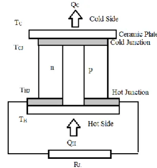
assembly is though in series electrically, however remains in parallel thermally [1]. The two sides are then strengthened through thin ceramic layers. The top layer, where the n- and p- semiconductor layers are shorted on a metal plate forms the cold junction (Jc), while the other end forms the hot junction (JH),
correspondingly the two sides are termed as coldand hot sides respectively. This definition of the cold and hot sides is based upon the flow of charges and the temperature difference established on the surfaces when a voltage source is applied to the isolated legs of the TEMcell, as suggested by the Peltier effect. This effect is reversible, viz., when the corresponding cold and hotsurfaces are maintained at a temperature difference, a voltage will developacross the cold and hotsurfaces. However, this voltage is very weak and therefore a suitable stacking is needed to collect a substantial voltage magnitude.
Fig1.Thermocouple in Thermoelectric Module
The stacked assembly is then encapsulated in a thermally conducting encasement [4]. Each semiconductor is called a pellet, and a TEM cell is composed of two dissimilar (n- and p- type semiconductor) pellets. These pellets aremade by using semiconductor Bismuth Telluride (Bi2Te3).Different compositions of Bismuth
Telluride with Antimony Telluride exhibit the well-knownrectifying behaviour.In commercial TEM’s,n- pellet is made by alloying (Bi2Te3)90with (Sb2Te3)10,
suffix indicates the percentage of alloying. Thus (Bi2Te3)90 means 90% Bi2Te3 used. Similarly, the
p-pallet is made by alloying (Bi2Te3)75 with (Sb2Te3)25.
Some High performance TEM’salso use (Bi2Te3)90
(Sb2Te3)5 (Sb2Se3)5 for n- pallet and (Bi2Te3)72
(Sb2Te3)25p-pallet respectively [5].
[image:2.595.64.218.393.558.2]The dimension of a TEM module,as shown in Fig.2, varies from vendor to vendor. Each individual vendor has its own geometrical and physical data to characterize their TEM’s.
Fig. 2.Thermoelectric Module
Usually the commoncharacteristics of TEM’s are stack size (N), length of pellet (L,mm), height of the packaged module (H, mm), Area of cross section of a TEM cell (A, sq.mm), Internal Resistance of the module (Rin,Ω), Thermal Conductivity (Kin, watt per
meter Kelvin) and the maximum operating temperature diferenceacross the hot and cold sides (Tmax). A commercial thermoelectric cooler (TEC) TB-127-1.4-1.2 fromKryotherm, is characterised by 254(TEM cells, N), 40.0 mm (length, L), 40.0mm (width, W),3.6 mm (height, H), 1.6Ω (Rin, Ω),
Seebeck Coefficient 0.0532V/K, 70K (∆TMAX) [1, 6].
3. PHYSICAL PHENOMEN RESPONSIBLE for
TEM OPERATION
Heat convection in thermoelectric module is a multistage process. Heat transfer rate depends on a physical constant 𝛌 (in watt per meter Kelvin).
Thermal conductivity and geometry of a single pellet is determined with the help of 𝛌,and the
equation for heat transfer in a pellet is described asfollows [1,4]
(1)
Heat flow, as normal, is opposed by the material characteristic, thus giving rise to thermal resistivity. Incorporating thermal resistance, Eq.1 can be re written as
(2)
where
(3)
Where H is height of the pellet (mm), A (sq.mm), it’s cross section area, T (K), temperature difference across cold and hot surfaces, q is heat (watt) and Θ (Kelvin per watt), thermal resistance of the pair of pellets in a cell. For N TEM cells in a module, total thermal resistance of the module is given by
Θin= /N (4)
Seebeck effect, gives the potential difference between the two ends of a conductor, subject to the temperature gradient along it’s length and can be given by [1-4]
U = α (TH -TC) (5)
U is electromotive force generated at the two ends of a single TEM cell. TH, TC arethe hot side and cold
side temperatures in Kelvin. In a TEM, two dissimilar materials are used, n-type and p-type, semiconductors, which commonly have apositiveSeebeck coefficient 𝛼pnin μ volt per Kelvin.
Total electromotive force in a TEM can be represented as follows
UTEM = N (𝛼p –𝛼n) (TH-TC)
Which can be rewritten as
UTEM = N 𝛼pn(TH -TC) (6)
UTEM is voltage generates at two end of
thermoelectric module,N is numbers of Thermocouples.
Peltier effect is anotherphenomenon, in which heatis pumped from hot junction to cold junction in a TEM when it carries electric current I, in ampere[1-4]. This phenomenon can be described by
q = I (𝛼p –𝛼n) (THJ -TCJ) (7)
Whereq is heat (in watt) pumped from hot to cold junction. αPand αnare Seebeck coefficients of p- and
n-type pellets (in μ volt per Kelvin).
Joule’s heating Pellets of a TEM cell are electrically semi conductive,therefore the cellshows electrical resistance. Joule heating is a physical process in which heat dissipateswhile electric current passes through it [3,4]. If resistance of the pellet is R (Ohm) and a current I (A) passes through, total heat dissipation is
q = RI2 (8)
R of a single couple of pellet can describe as
(9)
If TEM has N couples then, total resistance of a TEM is
Rin= R. N (10)
And hence, total heat dissipation is qN
4. ANALYSIS OF THE TEM
[6-8]. In the pallets of a TEM, majority careers (holesor electrons in the corresponding pallets) move from higher temperature to lower temperature. Its reverse process is responsible for a heat pump from higher temperature to lower temperature when TEM carries electric current. Total heat (Q=Σqi) flow from hot side to cold side in a TEM is a combination of Peltier effect, Heat convection from hot junction to cold junction and Joule heating [1,4].
QH=αpnTHJIL+ (THJ– TCJ)/Θ–IL2Rin/2 (11)
QC =αpnTCJIL+ (THJ– TCJ)/Θ+ IL2Rin/2 (12)
The QH and Q C is the heat flow rate, from hot
surface to hot junction and cold junction to cold side throw upper/ lower ceramic plate [3,4], Where Rinand Θ are electrical resistance and thermal
resistance of pellets respectively. Thermal convection in a thermoelectric module from hot junction to the cold junction can be given by [3,4].
TTEM = THJ -TCJ (13)
Similarly, thermal convection from hot side to cold side can be given by
= TH -TC (14)
Heat convection from a junction to the corresponding surface and from surface to the ambience are correlated through junction temperature and surface temperature difference TTEM and T, and can be defined by
TTEM = (15)
β is the correlation coefficient and is the temperature difference factor between the ceramic surfaces and the actual junctions [4], ignoring the effects responsible for any temperature difference between junctions. On connecting a TEM with a load resistance RL,IL flows. If TEM has
Nthermocouples, then IL can be given by
IL = VG/ (Rin+ RL)
= 𝛼pn / (Rin+RL) (16)
The output power delivered by a thermocouple cell can be given by [4]
PL= ILVL
= IL(𝛼pn –ILRin) (17)
With the help of Eqs. 16 and17,the TEM power can give by [4]
PL = (𝛼pn2 β2 T2) RL/(RL+Rin)2 (18)
At Rin equal to RL TEM will delivermaximum power
[4]
PMAX= (𝛼pn2 β2 T2) /(4Rin) (19)
Efficiency of a TEM cell is defined by the percentage (or ratio) of the transduction. Thus for a TEG, the efficiency is estimated theratio of the electrical energy supplied and the heat generated, and can be by [1]
η = (IL2 Rin)/QH (20)
Hence the figure of merit of a TEM module can be [1]
Z = 𝛼pn2Θin /Rin (21)
5. USE of TEM IN ENERGY RECYCLING
Commercial TEM modules are manufactured for cooling/heating and energy harvesting applications. Three thermoelectric modules are selected for energy harvesting applications from different vendors.Each of the TEM can also beused as a TEC orTEG.
temperature TC= 30, TH=200 Celsius and closed
circuit current is 2.8 A, and the open circuit voltage 4.1V. It’sthermal resistance is 0.57 K/W with electrical resistance 1.46 ohm [6].
Another TEG module TG12-8L from Marlow industries, has 4.97% efficiencyat operating temperature TC= 50 TH=230 Celsius. While open
circuit voltage is 9.43V, close circuit current is 3.38A, load resistances 3.46 Ohm and thermal resistance is 1.13 oC/W [7].
TEG from Hi-Z technology HZ-9, has 4.5% efficiency at operating temperature TC = 30, TH = 230oC. Open
circuit voltage 6.5V, close circuit current is 2.9A with internal resistance 1.15 Ohm[8].
Some researchershave suggested the use of TEM’s in energy recycling.A solar thermoelectric harvester was suggested by Pedro Carvalhaes Dias et al., in 2015. They demonstrated the energy recycling by using the TEM module TEG241-1.0-1.2
manufactured by Everredtronics
[9].Similarly,Vladimir Leonov, etal. suggested an energy harvesting method for low power devices on human body as thermoelectric converters of the animal warmth of a man for self-powered wireless sensor nodes in 2007,and demonstrated µW range energy harvesting with the help of TEG [2]. A Novel thermal management system for electrical and hybrid vehicles was suggested by ChakibAlaoui and Ziyad M. Salamesh in 2005 for temperature management in hybrid or electrical vehicles [3].
6. CONCLUSION
Thermoelectric effect is a physical phenomenon, which can be practically used for thermal heat pumping or energy harvesting. Commercial thermoelectric modules are specially designed for energy harvesting purpose.These modules are in their primary stage of growth and show efficiencies in the range 4 to 5% efficiency. Though the TEM’s show low efficiency, but they may serve as a potential candidate for the future developments in the field of energy harvesting due to their inherent advantages.
7. REFRENCE
[1] Simon Lineykin and Shmuel Ben-Yaakov, “Modeling and Analysis of Thermoelectric Modules” IEEE Transection on Industry Applications, Vol. 43, No. 2, March/April 2007
[2] VladimirLeonov, et.al., “Thermoelectric Converters of Human Warmth for Self-Powered Wireless Sensor Nodes”, IEEE SENSORS JOURNAL, Vol. 7, No. 5, MAY 2007.
[3] ChakibAlaoui and M. Salameh, “A Novel Thermal Management for Electric and Hybrid Vehicles” IEEE Transection on Vehicular Technology. Vol. 54, No. 2, March 2005
[4] SimoneDalola, Marco Ferrari, et.al, “Characterization of Thermoelectric Modulesfor Powering Autonomous Sensors”, IEEE TransectionOn Instrumentation and Measurement, Vol. 58, No. 1, January 2009
[5] Marc Hodes, “Optimal Design of Thermoelectric Refrigerators Embedded in a Thermal Resistance Network” IEEE Transection On Components, Packaging ACKAGING and Manufacturing Technology, Vol. 2, No. 3, March2012
[6] Product Catlogmenu,Kryotherm www.kryotherm.com
[7] Marlow industries,TG12-8L data sheet, www.marlow.com
[8] Hi-Z Technology, Hz-9 Datasheet, www.hi-z.com
BIOGRAPHIES
Irshad Ali is an M. Tech. scholar at Integral University, Lucknow, India. Currently he is working on a joint project with CSIR (Indian Institute of Toxicology& Research) Lucknow.