© 2016, IRJET | Impact Factor value: 4.45 | ISO 9001:2008 Certified Journal | Page 2200
Five Level Inverter to reduce Harmonics
Vijay Patil, Dr. V. V. Patil
21
Student, Dr. J. J. Magdum College of Engineering, Jaysingpur
2Professor, Dr. J. J. Magdum College of Engineering, Jaysingpur
---***---Abstract -
With the development in controllingtechnology, demand for the efficient power systems is increased in the market. It is difficult to achieve efficient power system by using traditional approach & arrangement of power component. Voltage converters, Inverters & UPS are most commonly used power sources. These sources mainly comprises of inverter block so demand for highly efficient, reliable and compact inverters is increasing in market. So as to achieve these requirements multi-level inverter technology are evolving. The multilevel inverters are suitable for various high voltage and high power applications due to their ability to synthesize waveforms with better harmonic spectrum , faithful output, size & efficiency . This paper deals with a five-level converter topology that follows this trend. In five-level, topologies and a theoretical power loss comparison as compare with two level inverter with the proposed solution is realized.
Key Words: Multilevel inverter, Two level inverter, Five level inverter.
1. INTRODUCTION
Currently two level & three level inverter topology are used widely. Level of inverter topology depends on the different voltage level available in the supplied DC source. Two & three level inverter topology is used in various applications such as in Uninterruptable Power Supply (UPS); Frequency converter (FC) & Inverters use for home appliances. It is also used at some other power conversion devices.
Here we are proposing the five level inverter topology which helps to reduce the harmonic content of the converters output voltage, which will reduce power losses, size and cost of filter circuit & leading to increase in efficiency of the inverter.
Five level inverter topology can replace the two level & three level inverters with addition of control mechanism with advantages of better efficiency, size & cost. So five level inverter can directly used in same field with its advantages. Multilevel topologies allows to reduce the harmonic content of the converter output voltage, allowing the use of smaller and cheaper output filters. Moreover, these topologies are usually characterized by a strong reduction of the switching voltages across the power switches, leading in the reduction of switching power losses and electromagnetic interference (EMI) [1]. In this paper, full-bridge topology with two additional power switches is used. Two diodes in series are
connected across conventional bridge & common point of diodes is connected to the midpoint of the dc link. Additional power switched are used to obtain different DC voltage levels. MATLAB/SIMULINK software is used to simulate five level & two level inverter topology.
[image:1.595.308.579.330.463.2]2. PROPOSED FIVE-LEVEL SINGLE-PHASE SOLUTION
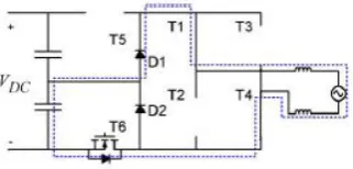
Fig. 1 shows proposed converter. This converter architecture is known as the H6 bridge & was originally developed in [2], combination with a suitable PWM strategy in order to keep common-mode voltage constant.
Fig. 1: Proposed converter
2.1 Working Principle:
The converter is constituted by full bridge inverter with an additional bidirectional switch (realized with an IGBT and four diodes), employed to connect the midpoint of the dc link to the converter output. The energy efficiency of this solution is potentially very high [2]; however, the capacitor’s voltage balancing is not taken into account. A variation with the positive rail of a full-bridge can be connected either to the dc link or to the midpoint of the dc-link capacitors. Only six devices are needed, and the maximum number of conducting devices is three. However, the balancing of the dc-link capacitors is a serious issue and limits the field of application to a reactive compensator [3].
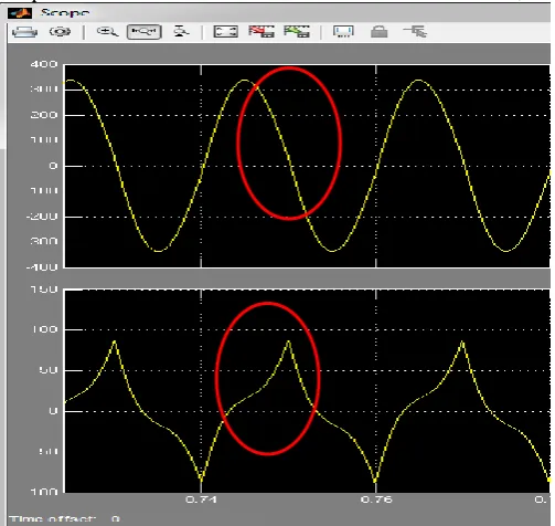
© 2016, IRJET | Impact Factor value: 4.45 | ISO 9001:2008 Certified Journal | Page 2201 Fig. 2: Output sine wave (Zone marking) & voltage
require at different Zone
The output voltage of the converter can be written as Vout =
mVdc [5][6]. Depending on the modulation index value, the power converter will be driven by different PWM strategies. As a matter of fact, it is possible to identify four operating zones (see Fig. 2), and for each zone, the output voltage levels of the power converter will be different [7][8].
2.2 Actual Working with Zones:
With reference to the schematic in Fig. 3, Fig. 4, Fig. 5 & Fig. 6 the behaviour of the proposed solution is shown for a whole period of the grid voltage, i.e., of the modulation index [9]. During the positive semi period the transistors T1 and T5 are ON and T2 and T3 are OFF.
[image:2.595.41.527.40.464.2]With reference to Fig. 3 in Zone 1, T5 is OFF and T6 commutates at the switching frequency, whereas in Zone 2 refer fig 5, T5 commutates at the switching frequency and T6 is ON. During the negative semi period the full-bridge changes configuration, with T1 and T5 OFF and T2 and T3 ON [10][11]. With similarity to Zone 1 and 2, in Zone 3 T5 commutates while T6 is OFF, and in Zone 5 T5 in ON and T6 commutates. Fig 3 shows proposed five-level PWM strategy for Zone 1.
Fig. 3: Active phase for zone
[image:2.595.340.514.221.446.2]Fig. 4: Freewheeling phase for zone 1
Fig. 5: Active phase for zone 2
Fig. 6: Freewheeling phase for zone 2
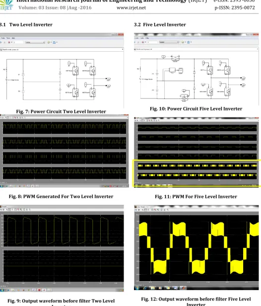
3. Simulation In MATLAB SIMULINK
Two level & Five level inverter simulation is done in MATLAB SIMULINK & results of same are recorded. Fig. 7 and Fig. 10 represents power circuit of Two & Five level inverter respectively. As shown in fig. 10 two switching devices are added in the series of DC source which are operated to achieve variable DC voltage applied to inverter IGBT bridge.
Fig. 8 & Fig. 11 shows the PWM signals used to drive the IGBT of Two level & five level inverters respectively. Two additional PWM signals highlighted in Fig. 11 are used to switch the devices connected in series of input DC supply. Switching operation of these devices is explained in section 2.1 & 2.2.
[image:2.595.82.243.599.676.2]© 2016, IRJET | Impact Factor value: 4.45 | ISO 9001:2008 Certified Journal | Page 2202 3.1 Two Level Inverter
Fig. 7: Power Circuit Two Level Inverter
Fig. 8: PWM Generated For Two Level Inverter
Fig. 9: Output waveform before filter Two Level Inverter
[image:3.595.38.565.56.672.2]3.2 Five Level Inverter
Fig. 10: Power Circuit Five Level Inverter
Fig. 11: PWM For Five Level Inverter
[image:3.595.309.563.120.260.2]© 2016, IRJET | Impact Factor value: 4.45 | ISO 9001:2008 Certified Journal | Page 2203 Fig. 13 & Fig. 14 shows output waveform of the Two
[image:4.595.305.557.95.337.2]Level & five Level inverter respectively. We need to higher value of inductor in two level inverter to achieve the same output sine waveform as achieved in Five level inverter,
Fig. 13: Output waveform after filter with L 5500mH of
Five Level Inverter
Table-1 shows comparative study of Two & Five level inverters in terms of efficiency & inductor value in the output filter circuit. Reduction of inductor value helps to achieve better efficiency due to reduced losses. Addition of two switching devices makes control part more complex compared to Two Level inverter.
Parameter Two Level Five Level
Inductor Use in output
filter 11500mH 5500mH
Efficiency at 25% Load 86% 96% Efficiency at 50% Load 86% 96% Efficiency at 75% Load 89% 98% Efficiency at 100% Load 89% 98% Size of Inverter Large Small
Control Complexity low High
Table -1: Comparison with two level (filter & efficiency)
[image:4.595.36.288.145.383.2]Fig. 15 shows the filter arrangement for both two & five level inverter. As shown in Table-1 value of inductor is different in Two & Five level inverter. Fig. 15 also shows the arrangement for measuring output efficiency & observing output waveforms. Final Output waveforms are shown in the fig 13 & 14.
Fig. 14: Output waveform after filter 11500mH of
[image:4.595.305.585.385.573.2]Two Level Inverter
Fig. 15: Output filter arrangement for Two Level & Five level inverter
4. Conclusion
© 2016, IRJET | Impact Factor value: 4.45 | ISO 9001:2008 Certified Journal | Page 2204
REFERENCES
[1] D. Infield, P. Onions, A. Simmons, and G. Smith, “Power
quality frommultiple grid-connected single-phase inverters,” IEEE Trans. Power Del.,vol. 19, no. 4, pp. 1983–1989, Oct. 2004.
[2] S. Lai and F. Z. Peng, “Multilevel converters—A new
breed ofpower converters,” IEEE Trans. Ind. Appl., vol. 32, no. 3, pp. 509–517,May 1996.
[3] D. Barater, G. Buticchi, A. S. Crinto, G. Franceschini, and
E. Lorenzani,“A new proposal for ground leakage current reduction in transformerlessgrid-connected converters for photovoltaic plants,” in Proc. 35th IEEEIECON, Nov. 2009, pp. 4531–4536.
[4] G. Buticchi, G. Franceschini, E. Lorenzani, D. Barater, and
A. Fratta, “Anovel compensation strategy of actual commutations for ground leakagecurrent reduction in PV transformerless converters,” in Proc. 36th IEEEIECON, Nov. 2010, pp. 3179–3184.
[5] R. Gonzalez, E. Gubia, J. Lopez, and L. Marroyo,
“Transformer less single-phase multilevel-based photovoltaic inverter,” IEEE Trans. Ind.Electron., vol. 55, no. 7, pp. 2694–2702, Jul. 2008.
[6] S. Kouro, M. Malinowski, K. Gopakumar, J. Pou, L.
Franquelo, B. Wu,J. Rodriguez, M. Pandrez, and J. Leon, “Recent advances and industrialapplications of multilevel converters,” IEEE Trans. Ind. Electron., vol. 57,no. 8, pp. 2553–2580, Aug. 2010.
[7] Giampaolo Buticchi, Emilio Lorenzani, and Giovanni
Franceschini, “A Five-Level Single-Phase Grid-ConnectedConverter for Renewable Distributed Systems”, IEEE Transactions on Industrial Electronics, Vol. 60, No. 3,pp. 906-918, March 2013
[8] Xiaoming Yuan; Stemmler, H.; Barbi, I. “Evaluation of
soft switching techniques for the neutral-point-clamped (NPC) inverter”, Power Electronics Specialists Conference, 1999. PESC 99. 30th Annual IEEE, Pages: 659 – 664
[9] Li Zhang; Kai Sun; Lanlan Feng; Hongfei Wu; Yan Xing,
“A Family of Neutral Point Clamped Full-Bridge Topologies for Transformerless Photovoltaic Grid-Tied Inverters”, IEEE Transactions on Power Electronics, 2013, Volume: 28, Issue: 2Pages: 730 – 739.
[10] Nabae.A., Takahashi.I., and Akagi. H., “A new
neutral-point clamped PWM inverter”, IEEE transactions on Industrial Applications, Vol. IA-17, pp. 518-523, September/October 1981.
[11] A. Bendre, G. Venkataramanan, D. Rosene, and V.
![Fig. 1 shows proposed converter. This converter architecture is known as the H6 bridge & was originally developed in [2], combination with a suitable PWM strategy in order to keep common-mode voltage constant](https://thumb-us.123doks.com/thumbv2/123dok_us/8188087.812599/1.595.308.579.330.463/converter-converter-architecture-originally-developed-combination-suitable-strategy.webp)