© 2016, IRJET | Impact Factor value: 4.45 | ISO 9001:2008 Certified Journal | Page 625
Designing Framework For Internetwork Using Switch Centric
Architecture
P.Keerthana
M.E(CSE) II year
Department Of Computer Science and Engineering,
Kongunadu College of Engineering and Technology, Tamil Nadu
India
[email protected]
Dr.J.Yogapriya
Professor&Dean
Department Of Computer Science and Engineering,
Kongunadu College of Engineering and Technology, Tamil Nadu
India
[email protected]
Mr.S.Satheesh Kumar
Assistant Professor
Department Of Computer Science and Engineering,
Kongunadu College of Engineering and Technology, Tamil Nadu
India
[email protected]
---***---Abstract -
The main objective of this paper to designing and building networks based on the fundamental concepts of Inter process Communication (IPC). From these design principles a smart architecture has been intend described Recursive Inter Network Architecture (RINA).In this paper, based on DSR protocol, we propose a detection scheme described the Cooperative Bait Detection Scheme (CBDS), which intends at perceiving and avoiding cruel nodes initiating gray hole/combined black hole attacks in MANETs. In this method, it incorporates the practical and reactive defence we will explore the security of RINA’s equivalent to a network layer, a Distributed IPC Facility (DIF). A DIF is the basic building block of RINA networks. Structural design and randomly cooperates with a stochastic neighboring node.Key Words: Inter process Communication, Recursive Inter Network Architecture, Cooperative Bait Detection Scheme, Distributed IPC Facility.
1. INTRODUCTION
MANETS improve transposition, safety and console ,The maintain a board ranges of applications that vehicles converse between the themselves and with the Internet, thereby enabling the configuration of networks of clever transposition arrangements vehicles converse with one another utilizing different wireless communication protocols to provide highly secure highway traffic environment.
MANETs can be protected employing stochastic learning automata based-based methods for intrusion identification MANETs can reduce on-road accidents get better the traffic circumstance by cooperatively allocation data regarding road situation traffic information ,and vehicular progress data in the middle of themselves.
Multi-path fading, obstruction and other wireless channel uniqueness results in the irregular connectivity trouble in Manet’s .Subsequently, two nodes can have connectivity problem while maintaining good connection with another node, even though both the nodes are within the communication range of each other. This irregular connectivity difficulty can be overcome by supportive communication methods in which the adjacent nodes listen to ongoing communication and transmit the message times of transmission failure. Uplink capacity of a node can be significantly recovered by employing user collaboration. MANETs can get better dependability and throughput gain by exploiting the transmit nature of wireless transmission by employing helpful communication practices.
2.
EXISTING SYSTEM
© 2016, IRJET | Impact Factor value: 4.45 | ISO 9001:2008 Certified Journal | Page 626
numerous network architectures (e.g., MANET,
infrastructure, mesh) and to accelerate prototyping solutions for evolving areas (e.g., psychological feature networks, cross-layer style, context-aware applications).Protocols, stubs for communication with intact layers, and management and higher-up functions are enforced as FINS Framework modules, interconnected by a central switch. This paper describes the FINS Framework design, presents associate initial assessment together with experiments enabled by the tool, associated documents an intuitive mechanism for transparently intercepting socket calls that maintains potency and suppleness.
3
.
PROPOSED SYSTEM
The proposed design is simulated over a huge number of MANET nodes with broad range of mobility and the performance is calculated. It is observed that proposed method creates improved packet delivery ratio, a smaller amount control overheads and decreased packet delay evaluated to Adhoc multipath division routing protocol (AOMDV).
4
.
ADVANTAGE
Wireless applications, like emergency searches, rescues, and military battlefields where sharing of information is mandatory. They provide access to information and services regardless of geographic position.Independence from central network administration Self configuring network nodes are also act as routers Less expensive as compared to wired network.Scalable accommodates the addition of more nodesImproved Flexiblibility.Robust due to decentralize administration.The network can be set up at any place and time.
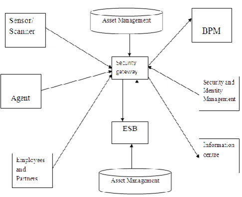
5. SYSTEM ARCHITECTURE
To determine combined black-hole attacks problem by designing a AODV routing as DSR-based routing apparatus, which is described CBDS (Cooperative Bait Detection Scheme) that integrates the advantages of both proactive and reactive defence structural designs. During my approach, the source node stochastically chooses a neighbouring node with which to institute assistance, the address of this node is utilized as inducement destination address to trick malicious nodes to send a RREP reply message spiteful nodes are therefore detected and avoided next to routing operation, by a reverse tracing method.
Asset Management
Business Process Management (BPM)
Enterprise Service Bus (ESB)
Security Gateway
Path Receiving
Two ways Communication
Fig -1: System architecture
5.1Explanation of Architecture diagram
Step 1: Read Section 1 for universal data
Step 2: Review Section 2 to choose an RFP pattern that suits you, if you do not previously have an RFP pattern for your association.
Step 3: suspiciously read the contents of Section 3 to build up an understanding of all the data arrested by STRAP.
Step 4: derived from the type of RFP (i.e., outsource only a little fraction versus everything), you can build a adapted RFP for your condition by extracting the required segments from Section 3 and customizing the practical content from the data shown in Section 3. If needed, you can appeal to the STRAP RFP Generator to make a outline adapted RFP to get you started
6. MODULES
The proposed algorithm for clustering can be done using basic steps.
6.1 Node Formation 6.2 Cluster Maintenance 6.3 Cluster Routing
6.1 Node Formation
[image:2.595.314.557.210.407.2]© 2016, IRJET | Impact Factor value: 4.45 | ISO 9001:2008 Certified Journal | Page 627 or may not be Gateways. Cluster Heads and Gateways are
vital elements in routing.
In the proposed algorithm, to reduce the network overhead, cluster size is limited to single hop. Every node has a NODE-ID and a CLUSTER-ID. The CLUSTER-ID is the identified of the cluster of which the node is a member. Every node maintains a GATEWAY-TABLE which contains the CLUSTER-IDs of Cluster Heads; it can reach by single hop. A cluster head maintains a MEMBERS-TABLE to keep the list of members joined to this cluster. The number of cluster members is called its DEGREE. Every node exchanges HELLO message to inform about their existence to its neighbour nodes and waits for CLUSTER_STATUS message from cluster head for a time period.
The neighbouring Cluster Head will reply with its CLUSTER_STATUS message, which contains the Degree of the cluster. If the node gets more than one CLUSTER_STATUS message, it will update this information in the GATEWAY-TABLE and it will choose the cluster with highest degree to join. Then the node can send a request message JOIN_REQUEST to join the cluster, indicating whether it is a Gateway node or not. The Cluster Head will check its DEGREE.
The node is allowed to join the cluster only if the DEGREE of the cluster is within the limits. This limits the number of Cluster Members and controls overhead of managing large number of Cluster Members by the Cluster Head. The cluster head sends a JOIN_ACCEPT message to the node if it can accept the request and updates the CLUSTER-MEMBERS table and the DEGREE. The requesting node sets the Head Status field in the GATEWAY-TABLE. If the node doesn’t receive a CLUSTER_STATUS message within the time period, the node will elect itself as Cluster Head and updated its CLUSTER-ID with its NODE-ID. It will set its DEGREE as zero.
6.2Cluster Maintenance
Cluster maintenance is needed when there is a failure in an active link of the network. A link failure can be detected by the loss of HELLO messages from neighbours. If the cluster head doesn’t receive HELLO message from its member within a time period, it will assume that the node is dead. The cluster head will delete the entry of the node from the members table. It also reduced its Degree by 1. If a node doesn’t receive CLUSTER_STATUS message from its Cluster Head within a time period, it will do the Cluster Join Procedure.
6.3Clustered Routing
In Clustered AODV a source node seeking to send a data packet to a destination node checks its route table to see if it has a valid route to the destination node. If a route exists, it simply forwards the packets to the next hop along the way to the destination. On the other hand, if there is no route in the table, the source node begins a route discovery process. It sends a route request (RREQ) packet to its Cluster Head. The Cluster Head checks to see whether its member node has a route to the destination or the destination node itself. If it has a route, it will reply with a route reply (RREP) packet. If
not, the Cluster Head will forward the RREQ packet to its Gateway Members. The Gateway members will forward the packet to Cluster Heads in its GATEWAY-TABLE. This process continues until the request reaches either an intermediate node with a route to the destination or the destination node itself. This route request packet contains the IP address of the source node, current sequence number, the IP address of the destination node, and the sequence number known last.
An intermediate node will reply to the route request packet only if they have a destination sequence number that is greater than or equal to the number contained in the route request packet header. When an intermediate node forwards route request packet, it will record in its route table the address of the neighbor from which the first copy of the packet has come from. This recorded information is later used to construct the reverse path for the route reply (RREP) packet
7. PROPOSED ALGORITHM
7.1Shortest path Algorithm:
The problem of finding the shortest path between two intersections on a road map (the graph's vertices correspond to intersections and the edges correspond to road segments, each weighted by the length of its road segment) may be modeled by a special case of the shortest path problem in graphs.
Shortest path algorithms are applied to automatically find directions between physical locations, such as driving
directions on web mapping websites
like MapQuest or Google Maps. For this application fast specialized algorithms are available.
If one represents a nondeterministic abstract machine as a graph where vertices describe states and edges describe possible transitions, shortest path algorithms can be used to find an optimal sequence of choices to reach a certain goal state, or to establish lower bounds on the time needed to reach a given state. For example, if vertices represent the states of a puzzle like a Rubik's Cube and each directed edge corresponds to a single move or turn, shortest path algorithms can be used to find a solution that uses the minimum possible number of moves.
In a networking or telecommunications mindset, this shortest path problem is sometimes called the min-delay path problem and usually tied with a widest path problem. For example, the algorithm may seek the shortest (min-delay) widest path, or widest shortest (min-(min-delay) path.
7.2Dual Queue Scheduling Algorithm:
© 2016, IRJET | Impact Factor value: 4.45 | ISO 9001:2008 Certified Journal | Page 628 generalized switch. First consider a saturated system in
which each user has infinite amount of data to be served. Prove the asymptotic optimality of the dual scheduling algorithm for such a system, which says that the vector of average service rates of the scheduling algorithm maximizes some aggregate concave utility functions.
7.2.1 Algorithm Steps:
Two steps:
7.2.1.1
Sending node
7.2.1.2
Pending node
7.2.1.1 Pending node
1: Broadcast PNODE REQ message to notify its neighbours that it is a pending node.
2: if receiving SWITCH CHNL then
3: Switch to channel c indicated in the message.
4: end if
7.2.1.2 Sending Node:
1: if its queue length for the receiving node < QT then 2: Broadcast SNODE REQ message to notify its neighbours that it is a sending node and the traffic load is below saturation.
3: end if
4: if receiving SWITCH CHNL then
5: if its receiving node ® is not negotiating with any other sending nodes then
6: Switch to channel c indicated in the message.
7: Notify r to switch to channel c.
8: end if
9: end if
8. USE CASE DIAGRAM
Could work with the software through its boundary. The use case illustrations illustrate scheme functionality as a set of tasks that the system should carry out and actors who cooperate with the method to finish the tasks.
Fig -2: Usecase diagram
Table –1: Actors and users
Actors Users
Brief Description The configure simulation use case helps in the initialization of the parameters to be used in the steps of simulation.
Trigger The parameters are initialized.
Pre-Conditions NS2 or NS3 simulation tool is running and initialized.
Post Conditions Parameters initiated for the
simulation.
Priority High
[image:4.595.309.554.73.251.2]Frequency Of Use It is always used by the user to perform the initialization of parameters.
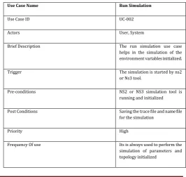
Table -2: Actors and user id
Use Case Name Run Simulation
Use Case ID UC-002
Actors User, System
Brief Description The run simulation use case helps in the simulation of the environment variables initialized.
Trigger The simulation is started by ns2
or Ns3 tool.
Pre-conditions NS2 or NS3 simulation tool is running and initialized
Post Conditions Saving the trace file and name file for the simulation
Priority High
[image:4.595.298.565.526.778.2]© 2016, IRJET | Impact Factor value: 4.45 | ISO 9001:2008 Certified Journal | Page 629
9. PERFORMANCE EVALUATION FOR MANET
A comparison of these two categories of routing protocols is presented, highlighting their features, differences, such as control traffic, control overhead, route acquisition delay, delay level, and characteristics of presented categories, a number of conclusions can be made from each category.
In proactive routing flat addressing can be simple to implement, however this method may not scale good for large networks By using a device such as GPS: Like in DREAM protocol where the nodes in the network just exchange their location information rather than complete links state or distance-vector information. By using conditional updates rather than periodic: For example in STAR updates occur based on conditions.
FSR have reduced the routing overhead by localizing the update message propagation. AODV which are flooding based have scalability problem. The Route discovery and route maintenance which are two main mechanisms of reactive routing protocols can be controlled in order to improve the scalability.
The CBRP protocol attempts to minimize the control overhead in route discovery phase by introducing a hierarchical on demand routing protocol. ABR routing protocol a localized broadcast query (LBQ) is initialized when a link goes down. ZRP protocol attempts in order to reduce the control overheads and delays.
9.1.1Ad-Hoc on Demand Distance Vector Routing
Protocol (AODV)
It plays an vital function in distance education, video-conferencing, co-operative work, and video on demand, duplicated database updating and querying, etc. some multicast routing procedures have been offered for Ad hoc networks, which are classified as also tree based or mesh based. In a mesh based multicast protocol, there may be in excess of one path among a couple of source and receiver, thus providing additional strength evaluated to tree based multicast protocols. During a tree based multicast protocol, there is only a on its own path among a pair of source and receiver, thus leading to superior multicast competence.
The structure of a multicast tree can be done moreover from the source (source-initiated) or from a receiver (receiver-initiated). The Ad hoc environment undergoes from recurrent path splits owing to mobility of nodes; therefore competent multicast group preservation is essential. Preserving the multicast cluster can be done by moreover soft state move towards or hard state approach. In the soft state approach, the multicast cluster partisanship and related routes are energized regularly which require flooding of organize packets. But, in the hard state approach, the routes are reconfigured only when a link breaks, thus making it a reactive scheme. Some examples of tree based multicast procedures are Ad hoc Multicast Routing
(AMRoute) Ad hoc Multicast Routing protocol utilizing Increasing id-numbers (AMRIS) , Bandwidth proficient Multicast procedure, Multicast process of the Ad hoc On require Distance Vector (MAODV) routing protocol , and Multicast Core- Extraction Distributed Ad hoc Routing (MCEDAR) protocol.
Chart -1: Key updation of graph
Chart -2: End to end delay
© 2016, IRJET | Impact Factor value: 4.45 | ISO 9001:2008 Certified Journal | Page 630
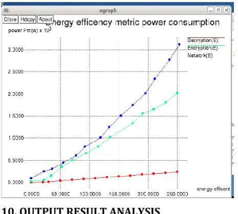
Chart -4: Energy efficiency metric power consumption
[image:6.595.307.524.109.266.2]10. OUTPUT RESULT ANALYSIS
[image:6.595.35.268.122.331.2]Fig -3: Ubuntu screen simulation output
Fig -4: Node formation
The node will be set and then all nodes are wi automatically
generated.
1. saving with time
2. Distance
3. Energy
Figure.10.Nodes are generated
11.CONCLUSION AND FUTURE WORK
Universal view of multicast routing procedures in ad-hoc networks. Some multicast routing protocol in MANETs tries to defeat some tricky difficulties which can be classified in basic problems or deliberations. All procedures have their own disadvantages and advantages. One builds multicast trees to decrease end-to-end latency. Multicast tree-based routing protocols are well-organized and satisfy scalability problem, they have some disadvantages in ad hoc wireless networks owing to mobile nature of nodes that contribute throughout multicast session.
Multicast mesh of exchange paths among all source-destination pair is instituted in mesh formation phase. Steady path within a mesh is created by choosing an SFN that possess superior value of link constancy between its neighbours. This promises improved quality of links and reduces the possibility of link breakdowns and the overhead needed to build the paths. In the mesh-based procedures offer additional strength against mobility and save the great size of manage overhead employed in tree preservation.
REFERENCES
[1]
W. Kiess and M. Mauve, “A survey on real-worldimplementations of mobile ad-hoc networks,” Ad Hoc Netw., vol. 5, no. 3, pp. 324–339, 2007.
[2] S. Kurkowski, T. Camp, and M. Colagrosso, “MANET simulation studies: The incredible,” ACM SIGMOBILE Mobile Comput. Commun.Rev., vol. 9, pp. 50–61, 2005.REED ET AL.: THE FINS FRAMEWORK: DESIGN AND IMPLEMENTATION OF THE FLEXIBLE INTERNETWORK STACK (FINS)... 501.
[3] OPNet Simulator [Online]. Available:
http://www.opnet.com/solutions/network_rd/modeler.htm l, 2012.
[4] NS2 Simulator [Online]. Available:
[image:6.595.35.264.355.683.2]© 2016, IRJET | Impact Factor value: 4.45 | ISO 9001:2008 Certified Journal | Page 631
[5] NS-3 Network Simulator. [Online]. Available: http://www.nsnam.org/, 2015.
[6] P. De, A. Raniwala, S. Sharma, and T. Chiueh, “Design considerations for a multihop wireless network testbed,” IEEE Commun. Mag., vol. 43, no. 10, pp. 102–109, Oct. 2005.
[7] V. Srivastava, A. B. Hilal, M. S. Thompson, J. N. Chattha, A. B.MacKenzie, and L. A. DaSilva, “Characterizing mobile ad hoc networks:The MANIAC challenge experiment,” in Proc. 3rd ACMInt. Workshop Wireless Netw. Testbeds, Exp. Eval. Characterization, 2008, pp. 65–72.
[8] A. S. Abdallah, A. B. MacKenzie, L. A. DaSilva, and M. S.Thompson, “On software tools and stack architectures forwireless network experiments,” in Proc. IEEE Wireless Commun.Networking Conf., Mar. 2011, pp. 2131–2136.
[9] E. Kohler, R. Morris, B. Chen, J. Jannotti, and M. F. Kaashoek,“The click modular router,” ACM Trans. Comput. Syst., vol. 18,pp. 263–297, Aug. 2000.
[10] E. Kohler, “Click for measurement,” UCLA Comput. Sci. Dept., Los Angeles, CA, USA, Tech. Rep. TR060010, Feb. 2006.
[11] A. Beach,M. Gartrell, S. Panichsakul, L. Chen, C. Ching, and R. Han,“X-Layer an experimental implementation of a cross-layer networkprotocol stack for wireless sensor networks,” Dept. Comput. Sci.,Univ. Colorado at Boulder, Boulder, CO, USA, Tech. Rep. CU-CS-1051-08, Dec. 2008.
[12] R. Buck, R. Lee, P. Lundrigan, and D. Zappala, “WiFu: A ComposableToolkit for Experimental Wireless Transport Protocols,” in Proc. IEEE 9th Int. Conf. Mobile Ad Hoc Sen. Syst., 2012, pp. 299–307.
[13] G. Bouabene, C. Jelger, and C. Tschudin, “Virtual networkstacks,” in Proc. PRESTO SIGCOMM Workshop, 2008, pp. 45–50.
[14] M. Berman, J. S. Chase, L. Landweber, A. Nakao, M. Ott,D. Raychaudhuri, R. Ricci, and I. Seskar, “GENI: A federated testbed for innovative network experiments,” Comput. Netw.vol. 61, no. 0, pp. 5–23, 2014.
[15] N. McKeown, T. Anderson, H. Balakrishnan, G. Parulkar,L. Peterson, J. Rexford, S. Shenker, and J. Turner, “Openflow:Enabling innovation in campus networks,” SIGCOMM Comput.Commun. Rev., vol. 38, no. 2, pp. 69–74, Mar. 2008.
[16] D. Raychaudhuri, I. Seskar, M. Ott, S. Ganu, K. Ramachandran,H. Kremo, R. Siracusa, H. Liu, and M. Singh,