International Journal of Emerging Technology and Advanced Engineering
Website: www.ijetae.com (ISSN 2250-2459,ISO 9001:2008 Certified Journal, Volume 5, Issue 4, April 2015)
Programmable Web Device
Kunal Pingle
1, Kalyani Nachankar
2, Pratik Shinde
3, Parag Shinde
4, Shubhangi Kamble
51UG Student, 2UG Student, 3UG Student, 4UG Student, 5Assistant Professor, Department of Electronics and Telecommunication Engineering, Rajendra Mane College of Engg. & Tech., Ambav (Devrukh) 415804, India
Abstract— The Programmable Web Device (PWD) is all about changing the whole and soul of the electronics. The Programmable web Device is an all in one device that will replace all the control and monitoring hardware systems in possibly every electronics. Thus building smart electronic systems which are very flexible. All in one is been said for the fact that PWD consists of different hubs capable of controlling and monitoring(E.g. Relay hub, amplifier hub, Driver hub).The pwd will be introduced in the electronics circuitry and through this device we can modify and monitor the functions of that particular electronics. The PWD has a microcontroller and Bluetooth module which control hardware and connection between a mobile respectively. Thus PWD will give us cost effective electronics with lesser hardware due to embedded computing via Google cloud. We have also introduced internet thus making the electronic system globally controllable. We have focused mainly on android mobiles through which we are going to control the PWD as well as the mobile will act as a routing device while we control it through a third device via the internet. Imagine devices without any additional buttons and control knobs thus lesser hardware and the machine will only serve the purpose or cause for which it is built and there is no need of any additional hardware for controlling which can be done merely through a mobile and for different machines. This means that a single mobile can replace multiple hardwares.
Keywords— GCM, Android, Bluetooth.
I. INTRODUCTION
The design approach is implementing a device which is applicable to all electronic appliances. As we know that most of the electrical appliance(viz. microwave oven, washing machine, air conditioner) includes electronic circuits. Most of the electronics consist of a microcontroller at their heart. These electronic circuits include sensors, indicators, displays, motors. PWD can be used as an effective and handy replacement for those electronic circuits The PWD is a partial SMD (surface mounted device) .The shape of our device is adaptive to its variety of applications. The most scintillating feature of the device is
The device is paired with Android based mobile. The device is paired via Bluetooth. Whenever the user goes beyond the Bluetooth range (10m approx.) the internet comes into play and the user can control it through internet. The internet requires a modem and an android device fulfills the same. The device receives data from the internet through Google account (Gmail).The Gmail accounts link each other via Google cloud messaging. Thus ultimately as the modem receives the data through the internet it sends it to the device. The PWD can be used in various kinds of electronic machines and appliances.
Explanation for Abbreviation PWD
P (Programmable): The device can change its functioning according to the changes in the android apps through which it’s controlled. Thus by merely changing the app we can change the functions of the PWD and eventually of electronic system
W (Web): The web comes into play when the user goes out of the Bluetooth range. But the most important part is that whenever the user requires any upgrade to any of the electronic system it would be provided through the web.
D (Device): The device stands for the compact and cost effective circuitry that is put into a single box. The device is very small easy to install.
II. ALL IN ONE DEVICE
International Journal of Emerging Technology and Advanced Engineering
Website: www.ijetae.com (ISSN 2250-2459,ISO 9001:2008 Certified Journal, Volume 5, Issue 4, April 2015)
III. HUBS
If PWD is the heart and brain of the concept then the hubs are the limbs. The hubs are controlled by the PWD after they are attached to the PWD. Every hub has a different function to perform. The five hubs of PWD are Relay hub, Motor driver hub, Voltage regulator hub, Amplifier hub, Rectifier hub.
A. Relay Hub
This hub consists of multiple relays. These multiple relays will be driven through the logical inputs provided by the microcontroller in the PWD. To drive those relays through the microcontroller we have introduced ULN2003. The relay hub is used for high voltage switching particularly in high voltage applications.
B.Amplifier Hub
This hub comprises of amplifiers, specifically its LM358. In this hub the voltage obtained from the sensor which is in millivolts is compared with a threshold of 5 volts and the gained output is amplified and forwarded to the microcontroller. Further microcontroller converts this analog input to digital.
C.Voltage regulator Hub
This hub consists of optocoupler (4N35) and TRIAC. This hub works on the principle of pulse width modulation. Thus it regulates the AC or DC voltages. So this hub helps to regulate the voltages of a wide range.
D.Motor driver Hub
This hub comprises of motor driver IC L293D. This hub is used to control the motors to rotate in clockwise and anticlockwise direction as per the voltage provided to L239D. The L293D receives its logical command from the microcontroller.
E.Rectifier Hub
This hub has transformer and rectifier diode (1N4007) as its prime components. The transformer is step down type thus it reduces the voltage. The rectifier converts AC voltage to DC. This Hub is the prime power supply of the entire PWD system. But this hub is not essential if batteries are used.
IV. AREAL TIME APPLICATION
International Journal of Emerging Technology and Advanced Engineering
Website: www.ijetae.com (ISSN 2250-2459,ISO 9001:2008 Certified Journal, Volume 5, Issue 4, April 2015)
V. DESIGN METHODOLOGY
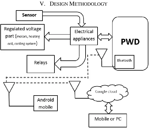
Fig 1.Functional block diagram of PWD system
The functional block diagram is as shown above displays the functioning of the entire system related to PWD and how it works. The various blocks show different parts of the system.
PWD:
The PWD has a Bluetooth module situated inside its structure and other than that it has a microcontroller (ATMEGA 328P). These two are the prime components of the PWD.
Android mobile:
This is cellular phone or a general phone which consist of Bluetooth as one of its feature and comprises of the android operating system capable of running the android apps.
Android OS:
Android is a mobile operating system (OS) based on the Linux kernel and currently developed by Google. With a user interface based on direct manipulation, Android is designed primarily for touchscreen mobile devices such as smartphones and tablet computers, with specialized user interfaces for televisions (Android TV), cars. The OS uses touch inputs that loosely correspond to real-world actions, like swiping, tapping, pinching, and reverse pinching to
Google Cloud messaging:
Google Cloud Messaging for Android (GCM) is a service that allows you to send data from your server to your users. Android-powered device, and also to receive messages from devices on the same connection. The GCM service handles all aspects of queuing of messages and delivery to the target Android application running on the target device. GCM is completely free no matter how big your messaging needs are, and there are no quotas.
VI. WORKFLOW DIAGRAM
A Workflow Diagram is a simple form of Flowchart depicting the flow of tasks or actions from one person or group to another. It typically consists of a set of symbols representing actions or individuals connected by arrows indicating the flow from one to another.
There are three workflow diagrams replicating three different processes.
1. Functioning between android mobile and PWD 2. Workflow if only Bluetooth is involved
[image:3.612.183.432.135.348.2]International Journal of Emerging Technology and Advanced Engineering
Website: www.ijetae.com (ISSN 2250-2459,ISO 9001:2008 Certified Journal, Volume 5, Issue 4, April 2015)
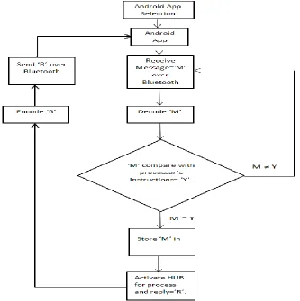
Fig 2. Functioning between android mobile and PWD
i) Functioning between android mobile and PWD:
As PWD is an all in one device we can carry out different functions using it. For these different functions we use different android apps. Hence as per our needs the respective android app changes. So the first block replicates the need for proper android app selection. The second block shows the android app that has been selected. Through this app we will send bits or byte form data. Here the byte form data is represented by ‘M’. The responsibility of carrying this data is carried out by the Bluetooth module present in the mobile and the data is received by the Bluetooth module in the PWD. This message is in encoded form. Thus after receiving the data it needs to be decoded.
[image:4.612.153.486.141.476.2]International Journal of Emerging Technology and Advanced Engineering
[image:5.612.120.436.156.403.2]Website: www.ijetae.com (ISSN 2250-2459,ISO 9001:2008 Certified Journal, Volume 5, Issue 4, April 2015)
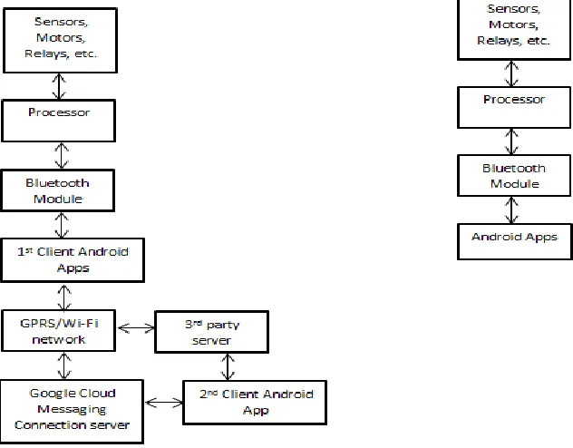
Fig 3. Workflow if both Internet and Bluetooth are involved
ii) Workflow if only Bluetooth is involved:
This flow shows a two way direction. Thus it means that the data flows evenly in both the directions. So moving from bottom towards the top the first block indicates android apps. As explained previously different functions require different android apps. Thus initially both the mobile and the Bluetooth module in the PWD are paired. After pairing the app sends bit or byte form of data via Bluetooth. This data is received by the Bluetooth module of the PWD and it is processed by the Processor and eventually it activates the hubs (sensors, Motor driver, relay etc.) as per the requirement.
iii) Workflow if both Internet and Bluetooth are involves:
This Block diagram is similar to the previous but with a different perspective. Here the android mobile which we were previously using as a controlling and monitoring device will now act as a modem for the internet to connect to the PWD. The block that shows 2nd client android app is the controlling and monitoring device. In order to connect
The Google cloud messaging has two servers. Thus the Google cloud messaging acts as connection server. This server is used for messaging that is sharing data between the1st client android app and the 2nd client android app. The 3rd party server is used for authentication between the two clients. The GPRS or WIFI provides the internet for the connection, authentication and messaging.
VII. CONCLUSION
Thus we conclude that the concept of PWD will be a boon not in the field of electronics but also many other engineering and research fields as well as to the endangered environment. Any individual can look forward to this successful idea and can use it for their respective research.
REFERENCES
[1] https://developer.android.com/distribute/googleplay/dev
eloperconsole.html
[2] https://cloud.google.com/docs/