International Journal of Emerging Technology and Advanced Engineering
Website: www.ijetae.com (ISSN 2250-2459,ISO 9001:2008 Certified Journal, Volume 8, Issue 12, December 2018)
87
General Mixed-Mode Universal Biquad Filter Using Three
CCIIs
Chen-Nong Lee
1, Wen-Chih Yang
21
Department of Computer and Communication Engineering, Taipei City University of Science and Technology, Taiwan, R. O. C.
2Department of Electrical Engineering, Taipei City University of Science and Technology, Taiwan, R. O. C.
Abstract— This paper presents a general mixed-mode (including voltage, current, transadmittance, and transimpedance modes) universal filter using only three second-generation current-conveyors (CCIIs), two grounded capacitors, two grounded resistors, and two floating resistors, which can realize all four modes five universal filtering responses (lowpass, highpass, bandpass, notch, and allpass) from the same topology. The proposed circuit uses only CCIIs with simpler implementation configuration than the other current-conveyors. This represents the attractive feature from chip area and power consumption point of view. Moreover, the proposed circuit offers the following features: (i) using two grounded capacitors, (ii) no component-value constraints except the voltage/transadmittance allpass response, (iii) no need of extra inverting or non-inverting amplifiers, (iv) no capacitors bringing extra poles degrading high-frequency performance, and (v) low active and passive sensitivity performance. H-Spice simulation results confirm the theory.
Keywords—Active filters, second-generation current conveyors (CCIIs), general mixed-mode, universal biquad filter.
I. INTRODUCTION
The applications and advantages in the designing general mixed-mode (including voltage-mode (VM), current-mode (CM), transadmittance-mode (TAM), and transimpedance-mode (TIM), i.e. four transimpedance-modes) active filters have received considerable attentions in recent years. This is because the mixed-mode operations such as TAM and TIM can play a very important role for transferring from VM to CM and vice versa, respectively. Therefore, the general mixed-mode active filters with input currents or/and voltages and output currents or/and voltages, are worthy of research and presented for the use of any filtering requirement.
In the past several decades, many mixed-mode filters using different active elements have been presented [1-38]. However, only several structures [1-4, 6-8, 10, 12, 15, 17, 22, 24, 25, 27, 31-34, 36, 38] can realize all five universal filtering functions (lowpass, highpass, bandpass, notch, and allpass) for all the four possible modes (i.e. VM, CM, TAM, and TIM).
International Journal of Emerging Technology and Advanced Engineering
Website: www.ijetae.com (ISSN 2250-2459,ISO 9001:2008 Certified Journal, Volume 8, Issue 12, December 2018)
88
Moreover, the CCCCTA is a complex active element.
The applications and advantages in the designing current-conveyor-based active circuits have received considerable attentions [1, 2, 6-11, 13, 14, 18, 20-24, 26, 27, 30, 31, 33-35, 37-46]. Especially, the second-generation current conveyor (CCII) has simplest implementation configuration in all of the other current conveyors, such as, DDCC, fully differential current conveyor (FDCCII), differential voltage current conveyors (DVCC), differential difference current conveyor transconductance amplifier (DDCCTA), current controlled current conveyor transconductance amplifiers
(CCCCTA), differential voltage current conveyor
transconductance amplifier (DVCCTA), digitally
programmable CCIIs (DPCCIIs), and dual X current conveyor differential input transconductance amplifier (DXCCDITA). The use of a FDCCII can be divided into two separate DDCCs. Similarly, a DDCCTA (CCCCTA, DVCCTA) also can be produced by cascading a DDCC (CCCII, DVCC) with an operational transconductance amplifier (OTA). Therefore, each of them can be regarded as two or more basic active elements. Only three general mixed-mode universal biquad filter structures employ two active elements [33, 34, 38]. In 2016, Lee proposed two mixed-mode universal biquad filters [33, 34]. The biquad filter in [34] uses two plus-type FDCCII, four grounded resistors, one floating resistor and two grounded capacitors. The circuit [34] has no need of any matching conditions which includes no need of component matching and no need of input matching conditions. The biquad filter in [33] uses one FDCCII, one DDCC, four grounded resistors, two floating resistors, and two grounded capacitors. The circuit has versatile input/output functions [33] which can offer all five universal filtering responses with multiple-input single output (MISO) and single-input multiple-output (SIMO) types, respectively. Similarly, in 2018, the very recently reported mixed-mode biquadratic filter [38] also uses two FDCCIIs in addition to four floating/grounded resistors and two grounded capacitors. The circuits in [33, 34, 38] use two active elements and can achieve many important advantages, but it was shown that the use of the complex active elements and many resistors was unavoidable. In 2009, Lee and Chang proposed a single FDCCII-based mixed-mode biquad filter [13]. The circuit [13] is based on one active element (i.e. FDCCII), two floating resistors, one grounded resistors, and two grounded capacitors. In 2017, the reported mixed-mode biquad filter [37] employs only a single active element (i.e. DXCCDITA) and four passive components.
Although single active element-based mixed-mode biquad filters have been proposed in [13, 37], both circuits [13, 37] are not general mixed-mode universal filters. Moreover, both used active elements (i.e. FDCCII and DXCCDITA) are complex active elements. In 2013 the reported mixed-mode [28] biquad filter using only two voltage differencing transconductance amplifiers (VDTAs) and two grounded capacitors can realize all five universal filtering functions, but the circuit in [28] only can be operated in VM and TAM.
If we are interested in mixed-mode universal biquad filters using only basic active elements such as CCIIs, then only few mixed-mode biquad filters using CCIIs which can realize all five universal filtering functions in all the four possible modes have been proposed [1, 2, 7, 10]. In [1], a CCII-based mixed-mode universal biquad filter is proposed. The biquad can realize VM, CM, TAM, and TIM five universal filtering responses. However, it needs to use seven CCIIs, eight resistors, and two grounded capacitors. In [2], a mixed-mode universal biquad filter using CCIIs is proposed. However, it needs to use five CCIIs, seven resistors, and two grounded capacitors. Although the mixed-mode universal biquad filters using only three CCIIs have been presented in [7, 10], the structures [7, 10] offer some disadvantages. For example, in [10], the mixed-mode biquad filter employs only three CCIIs, four resistors, and two capacitors but it needs to use two floating capacitors which are not attractive for monolithic IC implementation. Moreover, the biquad [10] needs to impose component choice for realizing VM / TAM lowpass, notch, allpass responses and CM / TIM highpass, notch, allpass responses. In [7], the mixed-mode biquad filter also employs three CCIIs but it needs to use one more capacitors and two switches in addition to four resistors and two grounded capacitors. Moreover, the biquad [7] needs to impose component choice for realizing highpass, notch, and allpass responses in CM, VM, TIM, and TAM. In 2013, Lee proposed a current-mode and transresistance-mode (i.e. transimpedance-mode) universal biquad filter [26]. Although the filter [26] employs only two multiple-output CCIIs (MOCCIIs), two grounded capacitors, and three grounded resistors, it can not be operated in VM and TAM.
International Journal of Emerging Technology and Advanced Engineering
Website: www.ijetae.com (ISSN 2250-2459,ISO 9001:2008 Certified Journal, Volume 8, Issue 12, December 2018)
89
In 2012, the reported multiple-mode (i.e. general mixed-mode) OTA-C universal filter [25] needs to use five OTAs in addition to two grounded capacitors for realizing second-order universal filter. In [17], the reported multiple-mode (i.e. general mixed-mode) universal biquad filter also needs to use five basic active elements (either five OTAs or four OTAs and one voltage inverter) in addition to two grounded capacitors. In [15], the reported mixed-mode universal biquad filter still needs to use five OTAs and two grounded capacitors. In 2014, Lee proposed a versatile transadmittance-mode biquad filter [29] using only three OTAs and two grounded capacitors. Although the circuit [29] can realize all five universal filtering functions with MISO and SIMO, the biquad in [29] only can be operated in TAM. In 2017, the recently reported general mixed-mode universal biquadratic filter [36] has SIMO feature, but it [36] needs to use six OTAs and two grounded capacitors.
In this paper, the proposed circuit uses only three CCIIs, two grounded capacitors, two grounded resistors and two floating resistors, which can realize VM, CM, TIM, and TAM all five universal filtering responses (lowpass, highpass, bandpass, notch, and allpass) from the same topology. Over the last decade, the general mixed-mode universal filters have been presented in the literature [1-4, 6-8, 10, 12, 15, 17, 22, 24, 25, 27, 31-34, 36, 38]. With respect to the references [1-3, 31, 32], the proposed circuit uses fewer active and passive elements. With respect to the references [4, 12, 15, 17, 25, 27, 36], the proposed circuit uses fewer active elements. With respect to the references [6, 8, 22, 24], the proposed circuit uses three CCIIs with simpler implementation configuration than three DDCCs. With respect to the references [7, 10], the proposed circuit employs active elements (CCIIs) in same number but the proposed biquad filter has the following advantages: less component matching conditions, the use of only two grounded capacitors and no switches. With respect to the references [33, 34, 38], the proposed circuit uses the basic
active elements with far simpler implementation
configuration than FDCCIIs.
II. PROPOSED CIRCUIT
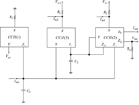
Figure 1 shows the proposed general mixed-mode biquad filter structure using only three CCIIs, two grounded capacitors (attractive for integrated circuit implementation), two grounded resistors, and two floating resistors, where Iin1, Iin2, Iin3 are the filter input currents and
Vin1, Vin2, Vin3 are the filter input voltages whose setting
determine the filter functions as shown later, Iout and Vout
are the filter current output and voltage output, respectively.
Using standard notation, the port relations of a CCII can be characterized by IY = 0, VX = VY, IZ+ = +IX, and IZ- = -IX. The multiple current outputs of CCIIs can be simply reconstructed using current mirrors. Moreover, the current output has very high output impedance. We notice that two grounded capacitors connected to the Z terminals of two CCIIs are attractive for integration and absorbing shunt parasitic capacitance. Moreover, three resistors at the X terminals of three CCIIs are suitable for absorbing series parasitic resistances of three CCIIs. If the active filter employs only resistors at the X terminals of the CCIIs, it can absorb series parasitic resistances at the X terminals of the CCIIs as a part of the main resistance (i.e. no capacitors
bringing extra poles degrading high-frequency
performance). Because the CCII has a series parasitic resistance at the X terminal (Rx), when the X terminal of
[image:3.612.329.560.361.536.2]CCII is not connected to a resistor, it leads to an improper transfer functions which do not exhibit good performance at high frequency [18, 26].
Figure 1. Proposed general mixed-mode biquad filter structure.
Routine circuit analysis for Figure 1 yields the following transfer functions:
) (
) ( ) (
4 2 1 2
s D G
s N s N G
Vout (1)
and
) (
) ( )
( 2
1 2
s D
s N s N G
Iout (2)
in which
3 3 1 2 1 1 1 2 1 2
1(s) s CC Vin sCGVin GGVin
International Journal of Emerging Technology and Advanced Engineering
Website: www.ijetae.com (ISSN 2250-2459,ISO 9001:2008 Certified Journal, Volume 8, Issue 12, December 2018)
90
3 2 1 2 2 1 1 2 1 22(s) s CC Iin sCG Iin GG Iin
N (4)
2 1 2 1 2 1 2 )
(s s CC sCG GG
D (5)
From Eqs. (1) - (5), the general mixed-mode biquad filter transfer functions are obtained according to input voltage or current conditions as follows.
Part I: If Iin1 = Iin2 = Iin3 = 0, the following VM and TAM
five universal filtering responses can be obtained from voltage output and current output as below.
(i) Highpass: Vin1 = Vin , and Vin2 = Vin3 = 0 (grounded).
(ii) Lowpass: Vin3 = Vin , and Vin1 = Vin2 = 0 (grounded).
(iii) Bandpass: Vin2 = Vin , and Vin1 = Vin3 = 0 (grounded).
(iv) Notch: Vin1 = Vin3 = Vin , and Vin2 = 0 (grounded).
(v) Allpass: Vin1 = Vin2 = Vin3and G1 = G2 = G3
Part II: If Vin1 = Vin2 = Vin3 = 0, the following TIM and CM
five universal filtering responses can be obtained from voltage output and current output as below.
(i) Highpass: Iin1 = Iin , and Iin2 = Iin3 = 0.
(ii) Lowpass: Iin3 = Iin , and Iin1 = Iin2 = 0.
(iii) Bandpass: Iin2 = Iin , and Iin1 = Iin3 = 0.
(iv) Notch: Iin1 = Iin3 = Iin , and Iin2 = 0.
(v) Allpass: Iin1 = Iin2 = Iin3 = Iin.
Note that it is no need to impose component choice in the design except VM/TAM allpass response. Moreover, no inverting or non-inverting amplifiers (for special input signals) are needed in the realizations.
Inspection of Eq. (5) shows that, in all cases the parameters ω0, ω0/Q, and Q are given by
2 1 2 1 0 C C G G
(6)
2 2 0 C G Q (7) 2 1 1 2 G C G C
Q (8)
From Eqs. (6) and (7), the parameters ω0 and ω0/Q can
be orthogonally adjustable by tuning the resistor R2 for
ω0/Q first and then resistor R1 for ω0 without disturbing
parameter ω0/Q. However, Eqs. (6) and (8) show that the
parameters ω0 and Q are interactive. The technique to
obtain the non-interactive filter parameter control can be suggested as follows [42].
For the fix-valued capacitors, the ω0 can be adjusted
arbitrarily without disturbing Q by simultaneously
changing resistor R1 and resistor R2 and keeping the G1/G2
constant. On the other hand, the parameter Q can be tuned
arbitrarily without disturbing ω0 by simultaneously
increasing 1/R1 and R2 and keeping the product G1G2
constant.
III. NONIDEAL ANALYSIS
Taking the tracking errors of the CCII into account, the relationship of the terminal voltages and currents can be written as: IY = 0, VX = β(s)VY, IZ± = ±α(s)IX, where α(s) and β(s) represent the frequency transfer functions of the internal current and voltage followers of the CCII. They can be approximated by the first order lowpass functions [18, 26, 43, 44]. For frequencies much less than the corner frequencies of the CCII, all α(s) and β(s) are real quantities of magnitudes slightly less than one [18, 26, 43, 44]. Assuming the circuit works at frequencies much less than the corner frequencies of α(s) and β(s), namely, α(s) = α = 1 -εi and εi (εi << 1) denotes the current tracking error of the
CCII and β(s) = β = 1-εv and εv (εv << 1) denotes the
voltage tracking error of the CCII. Taking into account the non-idealities of the CCII(1), CCII(2) and CCII(3), we obtain the non-idealities as below:
, 0
Y
I VX 1VY, IZ10IX, for CCII(1) (9)
, 0
Y
I VX 2VY, IZ 20IX, IZ121IX,
,
22
2 X
Z I
I IZ3a23IX, for CCII(2) (10)
, 0
Y
I VX 3VY, IZ30IX, for CCII(3) (11)
The non-ideal denominator of the mixed-mode transfer functions shown in Eqs. (1) to (5) becomes:
3 2 20 30 2 1 2 23 2 1 2 1 2 )
(s s CC sCG GG
D (12)
The ω0 and Q of the non-ideal mixed-mode biquad are:
2 1 2 1 2 3 20 30 0 C C G G
(13)
1 2 2 2 1 3 30 20 23 1 C G C G Q
(14)
The active and passive sensitivities of ω0 and Q are:
5
.
0
0 2 3 20 30 0 2 1 0 21, , , , ,
S
S
International Journal of Emerging Technology and Advanced Engineering
Website: www.ijetae.com (ISSN 2250-2459,ISO 9001:2008 Certified Journal, Volume 8, Issue 12, December 2018)
91
5
.
0
2 3 30 20 2 1 1
2, , , ,
Q Q QG C Q
G
C
S
S
S
S
,1
23
Q
S
, 00
1 23 22 21
10, , , ,
a
S
,0
1 22 21
10, , ,
Q a
S
(15)From Eq. (15), the proposed general mixed-mode biquad filter has low active and passive sensitivities (not larger than unity in absolute value).
IV. H-SPICE SIMULATIONS
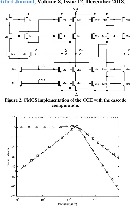
Two possible CMOS implementations of the CCII± are shown in Fig. 1 of Ref. [45] (without the cascode configuration) and Fig. 2 (with the cascode configuration) [46]. Note that if the cascode configuration is not used in CCII, DVCC, DDCC, FDCCII, VDTA, DDCCTA, DVCCTA, CCCCTA, DPCCII, and DXCCDITA, then the CCII has simplest implementation configuration in all of them. Similarly, if the cascode configuration is used in CCII, DVCC, DDCC, FDCCII, VDTA, DDCCTA, DVCCTA, CCCCTA, DPCCII, and DXCCDITA, then the CCII also has simplest implementation configuration in all of them. Note that the multiple current outputs (CCII) applying the realization of current replicas are very simple. To verify the theoretical analysis of the proposed universal filter, the H-SPICE simulations with the NMOS transistor aspect ratios (W/L=5μm/1μm) and PMOS transistor aspect ratios (W/L=10μm/1μm) of Fig. 2, using the TSMC 0.25μm process for the proposed circuit of Fig. 1, were performed with the component values: C1 = C2 = 8pF and
R1 = R2 = R3 = R4 = 9.947kΩ, for the mixed-mode lowpass,
bandpass, highpass, notch, and allpass filters, leading to a center frequency of f0 = 2MHz and quality factor of Q = 1.
Their supply voltages are VDD =-Vss = 1.25V, Vb1 = -
0.3V, and Vb2 = -0.6V. Fig. 3 presents the simulated
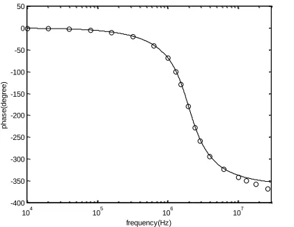
lowpass and bandpass amplitude-frequency responses of the proposed mixed-mode biquad filter with normalized voltage output and current output. Fig. 4 presents the
simulated highpass and notch amplitude-frequency
[image:5.612.330.560.122.480.2]responses of the proposed mixed-mode biquad filter with normalized voltage output and current output. Fig. 5 presents the simulated allpass phase-frequency responses of the proposed mixed-mode biquad filter with voltage output and current output. As can be seen, there is a close agreement between theory and simulation.
Figure 2. CMOS implementation of the CCII with the cascode configuration.
104 105 106 107 -70
-60 -50 -40 -30 -20 -10 0 10
frequency(Hz)
m
a
g
n
it
u
d
e
(d
b
)
Figure 3. Amplitude-frequency responses of the proposed mixed-mode biquad filter with normalized bandpass and lowpass filtering signals
( □, simulated bandpass; Δ, simulated lowpass; and ____, theoretical curve ).
105 106 107 -70
-60 -50 -40 -30 -20 -10 0 10
frequency(Hz)
m
a
g
n
it
u
d
e
(d
b
)
[image:5.612.334.560.486.685.2]International Journal of Emerging Technology and Advanced Engineering
Website: www.ijetae.com (ISSN 2250-2459,ISO 9001:2008 Certified Journal, Volume 8, Issue 12, December 2018)
92
104 105 106 107-400 -350 -300 -250 -200 -150 -100 -50 0 50
frequency(Hz)
p
h
a
s
e
(d
e
g
re
e
[image:6.612.65.276.144.307.2])
Figure 5. Phase frequency responses of the proposed mixed-mode biquad filter with allpass filtering signals ( ○, simulated phase; and
____, theoretical curve).
V. CONCLUSIONS
Only using three CCIIs (with simpler implementation configuration than the other current-conveyors), two grounded capacitors, two grounded resistors, and two floating resistors, to design a general mixed-mode universal biquad filter is presented in this paper. Filters using only basic active elements, such as CCIIs, have the advantages of the lowest cost, power dissipation, chip area, and noise. The proposed circuit can be operated in all four possible modes (i.e. VM, CM, TAM, and TIM) and can realize all five universal filtering responses (lowpass, highpass, bandpass, notch, and allpass) in the VM, CM, TAM, and TIM applications without changing the filter topology. Moreover, the proposed mixed-mode circuit still enjoys many main advantages: using two grounded capacitors attractive for integration and for absorbing shunt parasitic capacitance, no component-value constraints except the VM/TAM allpass responses, no inverting or non-inverting amplifiers for special input signals, no capacitors bringing extra poles degrading high-frequency performance, high output impedance, and low active and passive sensitivities. H-Spice simulations with TSMC 0.25μm process confirm the theoretical predictions.
Acknowledgements
The authors would like to thank the Ministry of Science and Technology of Taiwan, R. O. C. The Ministry of Science and Technology, Taiwan, R. O. C. supported this work under grant number MOST 107-2221-E-149-001-.
REFERENCES
[1] M. T. Abuelma’atti, A. Bentrcia, and S. M. Al-Shahrani, ―A novel mixed-mode current-conveyor-based filter,‖ Int. J. Electron., Vol. 91, No. 3, pp. 191-197, 2004.
[2] M. T. Abuelma’atti and A. Bentrcia, ―A novel mixed-mode CCII-based filter‖, Active and Passive Electronic Components, Vol. 27, pp.197-205, 2004.
[3] V. K. Singh, A. K. Singh, D. R. Bhaskar, and R. Senani, ―Novel mixed-mode universal biquad configuration‖, IEICE Electron. Express, Vol. 2, No. 22, pp. 548-553, 2005.
[4] M. T. Abuelma’atti and A. Bentrcia, ―A novel mixed-mode OTA-C universal filter,‖ Int. J. Electron., Vol. 92, No. 7, pp. 375-383, 2005. [5] N. A. Shah, and M. A. Malik, ―Multifunction mixed-mode filter
using FTFNs,‖ Analog Integr. Circuits Signal Process., Vol. 47, No. 3, pp. 339-343, 2006.
[6] C. M. Chang, C. N. Lee, C. L. Hou, J. W. Horng, and C. K. Tu, ―High-order DDCC-based general mixed-mode universal filter‖, IEE Proceedings Circuits, Devices and Systems, Vol. 153, No. 5, pp. 511-516, 2006.
[7] N. Pandey, S. K. Paul, A. Bhattacharyya, and S. B. Jain, ―A new mixed mode biquad using reduced number of active and passive elements‖, IEICE Electron. Express, Vol. 3, No. 6, pp. 115-121, 2006.
[8] C. N. Lee, C. M. Chang, C. L. Hou, and J. W. Horng, ―Cascadable multiple-mode universal biquad using fully grounded passive components‖, International Journal of Electrical Engineering, Vol. 14, No. 2, pp. 141-146, 2007.
[9] C. N. Lee, C. M. Chang, C. L. Hou, and J. W. Horng, ―Multiple-mode universal biquad filter using two DDCCs‖, International Journal of Electrical Engineering, Vol. 14, No. 4, pp. 291-298, 2007. [10] N. Pandey, S. K. Paul, A. Bhattacharyya, and S. B. Jain, ―Insensitive mixed mode biquad using reduced number of active and passive components‖, J. of Active and Passive Electronic Devices, Vol. 2, pp. 117-125, 2007.
[11] S. Minaei and M. A. Ibrahim, ―A mixed-mode KHN-biquad using DVCC and grounded passive elements suitable for direct cascading‖, International Journal of Circuit Theory and Applications, Vol. 37, No. 7, pp. 793-810, 2009.
[12] C. N. Lee and C. M. Chang, ―High-order mixed-mode OTA-C universal filter‖ AEU-International Journal of Electronics and Communications, Vol. 63, No. 6, pp. 517-521, 2009.
[13] C. N. Lee and C. M. Chang, ―Single FDCCII-based mixed-mode biquad filter with eight outputs‖ AEU-International Journal of Electronics and Communications, Vol. 63, No. 9, pp. 736-742, 2009. [14] L. Zhijun, ―Mixed-mode universal filter using MCCCII ‖ AEU-International Journal of Electronics and Communications, Vol. 63, No. 12, pp. 1072-1075, 2009.
[15] H. P. Chen, Y. Z. Liao, W. T. Lee, ―Tunable mixed-mode OTA-C universal filter‖ Analog Integr. Circuits Signal Process., Vol. 58, No. 2, pp. 135-141, 2009.
[16] N. A. Shah. and M. F. Rather, ―Electronically tunable current-mode/mixed-mode/voltage-mode multifunction active-only Biquads‖ J. of Active and Passive Electronic Devices, Vol. 4, No. 3, pp. 223-235, 2009.
International Journal of Emerging Technology and Advanced Engineering
Website: www.ijetae.com (ISSN 2250-2459,ISO 9001:2008 Certified Journal, Volume 8, Issue 12, December 2018)
93
[18] J. W. Horng, ―Current-mode and transimpedance-mode universal biquadratic filter using multiple outputs CCIIs‖, Indian Journal of Engineering & Materials Sciences, Vol. 17(June), pp. 169-174, 2010.
[19] E. Yuce, ―Fully integrable mixed-mode universal biquad with specific application of the CFOA‖, AEU-International Journal of Electronics and Communications, Vol. 64, No. 4, pp. 304-309, 2010. [20] J. W. Horng, ―High-order current-mode and transimpedance-mode universal filters with multiple-inputs and two-outputs using MOCCIIs‖, Radioengineering, Vol. 18, No. 4, pp. 537–543, 2009. [21] E. Yuce and S. Tokat, ―Design and stability analysis of mixed-mode
filters containing only grounded capacitors‖, Journal of Circuits, Systems, and Computers, Vol. 19, No. 6, pp. 1345-1363, 2010. [22] C. N. Lee, ―Fully cascadable mixed-mode universal filter biquad
using DDCCs and grounded passive Components‖, Journal of Circuits Systems and Computers, Vol. 20, No. 4, pp. 607-620, 2011. [23] S. Maheshwari, S. V. Singh, and D. S. Chauhan, ―Electronically tunable low-voltage mixed-mode universal biquad filter‖, IET Circuits Devices & Systems, Vol. 5, No. 3, pp.148-158, 2011. [24] W. B. Liao and J. C. Gu, ―SIMO type universal mixed-mode
biquadratic filter‖, Indian Journal of Engineering & Materials Sciences, Vol. 18(December), pp. 443-448, 2011.
[25] C. N. Lee, ―High-order multiple-mode and transadmittance-mode OTA-C universal filters‖, Journal of Circuits Systems and Computers, Vol. 21, No. 5, pp. 1250048 (21 pages), 2012. [26] C. N. Lee, ―Versatile universal current-mode and
transresistance-mode biquadratic filter using two MOCCIIs and grounded passive components‖, Journal of Circuits Systems and Computers, Vol. 22, No. 1, pp. 1250077 (18 pages), 2013.
[27] N. Pandey and S. K. Paul, ―Mixed mode universal filter‖, Journal of Circuits Systems and Computers, Vol. 22, No. 1, pp. 1250064 (10 pages), 2013.
[28] A. Yeşil and F. Kaçar, ―Electronically tunable resistorless mixed mode biquad filters‖, Radioengineering, Vol. 22, No. 4, pp. 1016– 1025, 2013.
[29] C. N. Lee, ―Versatile transadmittance-mode OTA-C universal biquad filter using minimum components with independently electronic tunability‖, Journal of Circuits Systems and Computers, Vol. 23, No. 7, 1450102 (18 pages) 2014.
[30] K. Ghosh and B. N. Ray, ―CCII-based Nth-order mixed mode elliptic filter with grounded R and C,‖ Journal of Circuits Systems and Computers, Vol. 24, No. 3, 1550035 (17 pages), 2015.
[31] D. Singh and N. Afzal, ―Fully digitally programmable generalized mixed mode universal filter configuration‖, Circuits Systems and Signal Processing, Vol. 35, No. 5, pp. 1457-1480, 2016.
[32] D. Singh and N. Afzal, ―Digitally programmable mixed mode universal filter using followers-a minimal realization,‖ Analog Integrated Circuits and Signal Processing, Vol. 86, No. 2, pp. 289-298, 2016.
[33] C. N. Lee, ―Independently tunable mixed-mode universal biquad filter with versatile input/output functions‖ AEU-International Journal of Electronics and Communications, Vol. 70, No. 8, pp. 1006-1019, 2016.
[34] C. N. Lee, ―Mixed-mode universal biquadratic filter with no need of matching conditions‖, Journal of Circuits Systems and Computers, Vol. 25, No. 9, 1650106 (24 pages), 2016.
[35] H. P. Chen and W. S. Yang, ―Electronically tunable current controlled current conveyor transconductance amplifier-based mixed-mode biquadratic filter with resistorless and grounded capacitors‖, Applied Sciences, Vol. 7, No. 3, 244 (22 pages), 2017. [36] M. Parvizi, A. Taghizadeh, H. Mahmoodian, and Z. D. Kozehkanani,
―A low-power mixed-mode SIMO universal G(m)-C filter‖, Journal of Circuits Systems and Computers, Vol. 26, No. 10, 1750164 (16 pages), 2017.
[37] M. Faseehuddin, J. Sampe, S. Shireen, and S. H. Md Ali, ―A novel mix-mode universal filter employing a single active element and minimum number of passive components‖ Informacije MIDEM-Journal of Microelectronics Electronic Components and Materials, Vol. 47, No. 4, 211-221, 2017.
[38] B. Chaturvedi, J. Mohan, and A. Kumar, ―A new versatile universal biquad configuration for emerging signal processing applications‖, Journal of Circuits Systems and Computers, Vol. 27, No. 12, 1850196, 2018.
[39] C. N. Lee ―Independently tunable high-input impedance voltage-mode universal biquadratic filter using grounded passive components‖ Indian Journal of Pure & Applied Physics, Vol. 53, No. 9, 625-634, 2015.
[40] C. N. Lee, ―Independently tunable plus-type DDCC-based voltage-mode universal biquad filter with MISO and SIMO types‖ Microelectronics Journal, Vol. 67, pp. 71-81, 2017
[41] E. Yuce and S. Minaei, ―ICCII-based universal current-mode analog filter employing only grounded passive components,‖ Analog Integrated Circuits and Signal Processing, Vol. 58, No. 2, pp. 161-169, 2009.
[42] O. Channumsin, T. Pukkalanun, W. Tangsrirat, Voltage-mode universal filter with one input and five outputs using DDCCTAs and all-grounded passive components, Microelectronics Journal, Vol. 43, pp. 555–561, 2012.
[43] A. Fabre, O. Saaid, and H. Barthelemy, ―On the frequency limitations of the circuits based on second generation current conveyors‖, Analog Integrated Circuits and Signal Processing Vol. 7, pp. 113-129, 1995.
[44] J. W. Horng, C. L. Hou, C. M. Chang, W. Y. Chung, and H. Y. Wei, ―Voltage-mode universal biquadratic filters with one input and five outputs using MOCCIIs‖, Computers and Electrical Engineering, Vol. 31, pp. 190-202, 2005.
[45] W. Surakampontorn, V. Riewruja, K. Kumwachara, and K. Dejhan, ―Accurate CMOS-based current conveyors‖, IEEE Transactions on Instrumentation and Measurement, Vol. 40, No. 4, pp. 699–702, 1991.