2018 International Conference on Applied Mechanics, Mathematics, Modeling and Simulation (AMMMS 2018) ISBN: 978-1-60595-589-6
Parameter Identification of Low Frequency Oscillation Based on Fourier
Synchrosqueezing Transform
Wen-bo WANG
1,*, Yun-yu JIN
1, Bin WANG
2, Qi DI
1and Min YU
11
School of Science, Wuhan University of Science and Technology, China Wuhan, China
2
School of Information Science and Engineering,
Wuhan University of Science and Technology, China Wuhan, China
*Corresponding author
Keywords: Fourier-based synchrosqueezing transform, Low frequency oscillation, Instantaneous parameters, Damping ratio.
Abstract. In this paper, the Fourier-based synchrosqueezing transform (FSST) method is introduced into the power system to realize low frequency oscillation identification. Firstly, the modal components of low frequency oscillation signal are separated by FSST, and calculating the instantaneous parameters including magnitude, frequency and phase of every mode component with Hilbert transform. Then, calculating the damping ration of every modal component based on above parameters and derived the formulas. Thus, it realized effective identification of modal parameters of low frequency oscillation signal. The experimental results of simulated data and 16-generator system demonstrate the validity and correctness of the FSST method. Comparing with the classical Prony method shows that the FSST method is better in the identification accuracy when the low frequency oscillation signal is polluted by noise. Finally, the effectiveness of the FSST in Actual power grid is verified based on the real data from Sichuan power grid.
Introduction
With the increase of the scale of the power grid, the increase of long- distance transmission and weak interconnection of electric power and the large use of fast high magnification quick excitation device, transient stability of the power grid and voltage quality are improved but the oscillation instability of the power system is exacerbated. These factors are likely to lead to low-frequency oscillation phenomenon of weak damping[1-3]. In recent years, there have been many low-frequency oscillations in power grids both at home and abroad[4], which has brought great harm to the power system and has become the bottleneck that limits the transmission capacity of the interconnected power grid. Stability is an important issue for large power grids, and the identification of low-frequency oscillation can provide an effective basis for the stable operation of power grid and damping control[5]. In recent years, the phasor measurement units(PMU) has been widely used in power system, which provides the basis for the low frequency oscillation analysis based on the measurement data. Because the measured data truly reflected the dynamic characteristics of the system, the analysis method based on the measured PMU data has a broad application prospect. Now, many methods to identify low frequency oscillations based on PMU data have been proposed.
ridge method is proposed in [12,13] to process the time-varying oscillatory signals, which is of great significance in the identification of low frequency oscillation, but this method can’t obtain high accuracy results when extracting multi-frequency component signals.
FSST (Fourier Synchrosqueezing Transform) is a non-linear time-frequency reassigned algorithm which is developed on the basis of Short-time Fourier Transform[14]. FSST can obtain higher accuracy time-frequency curve and improve the modal mixing phenomenon very well by squeezing the coefficients of short time Fourier transform in the direction of frequency. Even if the signal to be decomposed contains multiple harmonic signals with relatively close frequencies, FSST can still extract them one by one[15]. Moreover, the FSST has good robustness to noises. When the multiple harmonic signal is polluted by noise, the FSST can still obtain a clear time-frequency curve and an approximate invariant decomposition result[16]. Fourier Synchrosqueezing Transform has been successfully applied to the instantaneous frequency calculation[17], gravitational wave analysis[18], vibration signal analysis[19] and so on. In this paper, FSST is applied to the parameter extraction of low frequency oscillation in power system. Firstly, the low-frequency oscillation modes are separated by FSST. Then, the instantaneous frequency and amplitude of modal are calculated by Hilbert transform, and the damping ratio is calculated by instantaneous amplitude and frequency. Finally, the simulation data, IEEE 16-machine 39-node system data and measured data of Sichuan Provincial Power Grid are tested, and compared with the identification results of Prony algorithm. The experimental results verify the effectiveness and accuracy of the proposed method.
Theoretical of Low Frequency Oscillation Parameter Identification by FSST
FSST Decomposition of Low Frequency Oscillation Signal
When the given window function is g, the short-time Fourier transform of signal ( )f t is defined as * 2 ( )
( , ) ( ) ( )
g i t
f R
V t
f g t e dLow-frequency oscillation signals f t( )often contain multiple components, and each component has its own local feature. f t( ) can be expressed as
1 1
( ) ( ) ( ) ( ) cos( ( )) ( )
K K
k k k
k k
f t f t r t A t t r t
(1) where ( ) kt
k k
A t A e is the instantaneous amplitude of the kth component, k( )t ktkis the instantaneous phase of the kth component, r t( ) is noise or error and K represents the number of signal components. It has been shown that in the time-frequency map of the Short-time Fourier Transform, the frequency spectra of the signal is wide and the boundary is ambiguous[14,15]. For the more complex multi-component signals, there are often severe spectral aliasing between the STFT spectra of the component signals f tk( ).
FSST is based on Short-time Fourier transform, and by refining the time-frequency curve of STFT, the amplitude A tk( ) and instantaneous frequency k( )t of each component f tk( ) can be
effectively extracted. As a special reorganization method, FSST reassigns the coefficient Vfg( , )t to
different points [ ,t ˆf( , )]t in the time-frequency plane according to local properties of STFT
coefficient g( , )
f
V t (ˆ ( , )f t denotes the instantaneous frequency of the signal at ( , )t ). Therefore,
FSST makes the time-frequency curve more detailed and clearer. The frequency resolution is improved and the modal mixing is reduced in the time-frequency map of FSST, so the reconstruction precision of the component signal is obviously higher.
( , ) 1
ˆ ( , )= arg{ ( , )}
2 2 ( , )
g f g
f t f g
f
V t
t V t R
i V t
where arg{ }Z and R Z{ } denote the argument and the real part of the complex Z respectively, and
t
denotes the partial derivative of the function for t.
Based on the instantaneous frequency, FSST establishs the mapping from ( , )t [ ,t ˆf( , )]t , and
the STFT coefficient Vfg( , )t is transformed from the “t“ plane to the “tˆ ( , )f t “ plane. In
FSST, the STFT coefficients in the interval [ˆ 1 , ˆ 1 ]
2 2
f f
with certain center frequency ˆf
are squeezed to the center frequency ˆf and obtain the FSST value Tfg,( , )t . Synchronous squeeze of STFT coefficient can achieve the purpose of improving frequency resolution and reducing frequency mixing. In the actual calculation, the calculation formula of FSST coefficient is:
, * { ,| ( , )| } 1 ˆ ( , ) ( , ) [ ( , )] (0) g f g g
f V t f f
T t V t t d
g
where is the given threshold. Comparing the time-frequency spectrums of FSST, CWT and STFT by a time-varying signal ( )f t .
The FSST transform is reversible. For multi-component signals, ,
( , )
g f
T t can not only reconstruct
the original signal ( )f t , but also reconstruct each component signal f tk( ) accurately. Suppose that
( ,t k( ))t is the Kth ridge line of ( )f t , the reconstruction formula of f tk( ) is[14]
, { ,| ( )| }
( ) ( , )
k
g
k t d f
f t T t d
(2)where k( )t which is usually calculated by ridge extraction is an approximate estimate of k( )t , and
d is the given ridge error threshold[17]. Compared with FSST and STFT (as shown in Figure 1), STFT decomposition cannot achieve accurate division of the frequency band, and there are often serious spectrum mixing and energy leakage between sub-bands. However, the frequency band of the time-varying signal ( )f t can be more accurately divided by FSST, and the spectrum mixing between sub-bands is better weakened. Therefore, each component f tk( ) can be accurately reconstructed from different frequency spectral sub-band, and then the amplitude, frequency and damping parameter of the component signal f tk( ) can be obtained. So, this paper adopts FSST to identify the parameters of low frequency oscillation signal of the power system.
Hilbert Transform of Low Frequency Oscillation Mode Components
In the low-frequency oscillation of power system, an oscillation mode component can be expressed as:
( ) tcos( )
x t Ae t (3) where A is the initial amplitude, is the initial phase angle, is the attenuation coefficient and is the oscillation angle frequency. For continuous signal x t( ), its Hilbert transform is
1 ( )
( ) x
y t d
t
(4) Then the corresponding analytic signal is obtained as( ) ( ) ( ) ( ) ( ) j t
z t x t jy t a t e (5)
2 2
( ) ( ) ( )
a t x t y t , ( ) arctan ( ) ( )
y t t
x t
(6)
The instantaneous frequency is calculated as: ( ) 1 ( ) 2
d t
f t
dt
. Comparing formula (3) and (5),it
can conclude that
( )
( )
t
a t Ae
t t
By introducing a logarithmic operator on ( )a t ,the following equation is obtained :
ln ( )a t t lnA (7) where ln ( )a t is a linear function of time. In order to obtain the attenuation coefficient and the initial amplitude A accurately, the least squares fitting of the linear function is carried out to ln ( )a t . Then the fitting slope is () and the fitting intercept is lnA.
The instantaneous phase of the analytic signal is
( )t t
(8) In order to obtain the angular frequency and the initial phase angle accurately, the least square fitting of the linear function is performed to phase. Then the fitted slope is the angular frequency and the fitted intercept is the initial phase angle .
Damping Ratio of Low Frequency Oscillation Mode Component
According to control theory, the oscillation mode component ( )x t Aetcos( t ) has the oscillation characteristics in the damping oscillation as follows:
0 2
0 0
( ) tcos( 1 )
x t A e t
where is damping ratio and 0 is un-damped frequency. Thus,
0 2 0 1
Therefore, the damping ratio is calculated as
2 2
(9)
Steps of Identifying Low Frequency Oscillation Mode Parameters
The identifying steps of low frequency oscillation modal parameters by using of FSST method are as follows.
Step 1: the original low frequency oscillation signal is decomposed by FSST, and a group intrinsic mode type function(IMTF) are obtained.
Step 2: The Hilbert transform of each IMTF is carried out, and the instantaneous amplitude a t( )
and instantaneous phase ( )t are identified according to the formula (6).
Step 3: calculating the logarithm of instantaneous amplitude a t( ), then the least square fitting of the linear function is used to fit the logarithm of a t( ). The opposite number of the fitted slope is the attenuation coefficient , and the fitted intercept is the lnA, then the initial amplitude A can be obtained.
Step 4: Perform the least square fitting of the linear function to phase ( )t . The fitted slope is the
Step 5: calculating the damping coefficient according to equation (9).
Repeat steps 2 to 5 above to complete the identification of low-frequency oscillation parameters.
Simulation Experiment and Analysis
Analysis of Simulation Low Frequency Oscillation Signal
The low frequency oscillation signal can be seen as a linear combination of some cosine signals (oscillating mode) with certain frequency, and the amplitudes of which change according to the exponential function. Then the low frequency oscillation data with random noise can be expressed as
1
( ) i cos(2 ) ( )
n t
i i i
i
x t A e f t t
where ( )t is white noise. A test signal with noise is constructed as
0.1 0.3
0( ) 1( ) 2( ) ( ) 2 cos(2 0.5 ) cos(2 1.2 ) ( )
3 6
t t
x t x t x t t e t e t t
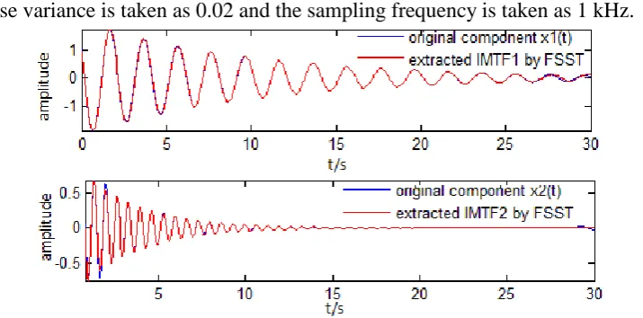
[image:5.595.102.460.327.504.2]The frequency of x t0( ) satisfies the frequency range of the low-frequency oscillation(0.2 ~ 2.5Hz), and x t0( )contains different attenuation coefficients and phase angles. The white noise variance is taken as 0.02 and the sampling frequency is taken as 1 kHz.
Figure 2. Decomposition results of simulation data by FSST.
[image:5.595.76.494.556.695.2]The FSST decomposition result of x t0( ) is shown in Fig,2. From Fig.2, it can be seen that two IMTFs c1 and c2are obtained after FSST decomposition. To verify the correctness of the signal decomposition by the FSST, an error curve between the original signal without noise and the signal reconstructed by two IMTFs is given, as shown in Figure 3.
Figure 3. Reconstruction error of FSST.
Figure 4. Parameter identification processing by FSST.
After the fitting calculation, it can be found that c1 is a low-frequency oscillation mode with an amplitude of 2.00226MW, a frequency of 0.50055Hz, and an attenuation of 1.0067. The oscillation parameters can be obtained by the same processing for c2.After the identification results of Prony method are obtained, comparing the identification results of two methods and the ideal value of parameters, and the comparing results are shown in Table 1.
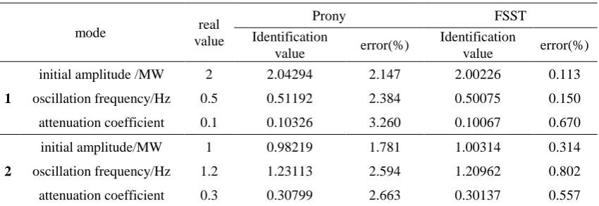
Table 1. Parameter identification of simulation data.
mode real
value
Prony FSST
Identification
value error(%)
Identification
value error(%)
initial amplitude /MW 2 2.04294 2.147 2.00226 0.113
1 oscillation frequency/Hz 0.5 0.51192 2.384 0.50075 0.150
attenuation coefficient 0.1 0.10326 3.260 0.10067 0.670
initial amplitude/MW 1 0.98219 1.781 1.00314 0.314
2 oscillation frequency/Hz 1.2 1.23113 2.594 1.20962 0.802
attenuation coefficient 0.3 0.30799 2.663 0.30137 0.557
It is known from Table 1 that the maximum relative errors of initial amplitude, oscillation frequency and attenuation coefficient obtained by Prony method are 2.147%, 2.594%, 3.260%, respectively; and the maximum relative errors of initial amplitude, oscillation frequency and attenuation coefficient obtained by FSST are 0.314%, 0.802%, 0.670%, respectively. For the simulation data, it can be seen that the FSST method can accurately identify the parameters of the low frequency oscillation signal, and the identification results are better than the classic Prony method.
Low Frequency Oscillation Analysis of 16 Machines and 39 Nodes System
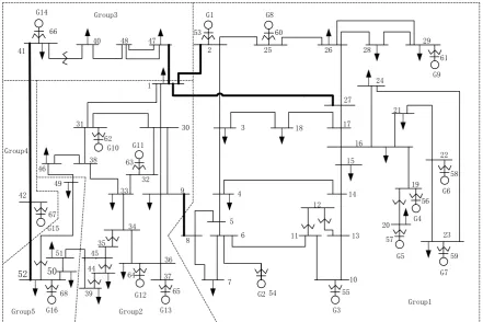
[image:6.595.87.512.348.494.2]G14 G11 G10 G15 G16 G13 G2 G3 G7 G5 G4 G6 G9 G8 G1 G12 66 41 42 67 52 68 39 50 51 45 44
40 48 47
[image:7.595.79.521.70.364.2]1 2 53 25 60 26 28 29 61 24 27 17 16 21 22 58 19 56 15 14 13 10 55 54 6 11 5 4 12 8 9 36 37 65 64 34 35 49 46 38 31 62 63 32 33 59 23 7 57 20 18 3 30 Group1 Group2 Group3 Group4 Group5
Figure 5. The 16-mechine system.
The system can be divided into five areas: Group1 (G1 to G9), Group2 (G10 to G13), Group3 (G14), Group4 (G15), Group5 (G16). By solving the eigenvalues of the state matrix of the system linearization model, there are 4 inter-area oscillation modes in the system, as shown in Table 2.
Table 2. Real parameters of low frequency oscillation of 16 machine system.
mode Oscillation frequency/Hz damping ratio /%
1 0.388 5.02
2 0.522 0.85
3 0.677 3.91
4 0.793 3.53
Mode 1 is the oscillation of Group1 and Group2 relative to Group3 to Group5, Mode 2 is the oscillation of Group1 to Group4 relative to Group5, Mode 3 is the oscillation of Group1 relative to Group2 and Mode 4 is the oscillation of Group3 and Group5 relative to Group4. The active power of line 1-47 and 8-9 are selected respectively to monitor mode 1 and mode 3, and the active power of line 41-42 are selected to monitor mode 2 and mode 4.
In order to simulate the small random fluctuation of the load in the power system, 0.5% load is set as the random fluctuation load at the main load point of the 16 machine system. The simulation time is 10 min. After obtaining the system free oscillation signal, in order to verify the robustness of the proposed method to noise, 5dB Gaussian white noise is superposed with the ideal signal obtained by the simulation.
[image:7.595.81.512.458.544.2]Table 3. Identification results of frequency and damping ratio.
mode
Prony FSST
Identification value error(%) Identification value error(%)
1 Oscillation frequency/Hz 0.37642 2.985 0.38432 0.948
Damping ratio/% 5.368 6.932 5.071 1.016
2 Oscillation frequency/Hz 0.54414 4.241 0.52634 0.831
Damping ratio/% 0.798 6.118 0.842 0.941
3 Oscillation frequency/Hz 0.65571 3.145 1.20962 0.619
Damping ratio/% 4.079 4.319 3.943 0.842
4 Oscillation frequency/Hz 0.78447 1.076 0.78580 0.908
Damping ratio/% 3.718 5.332 3.501 0.822
It can be seen from table 3 that the maximum frequency error of the proposed method is 0.948%, and the maximum frequency error of Prony method is 4.241%. Comparing the obtained frequency identification results of 4 modes by the proposed method and Prony method, it is found that the frequency identification effect of FSST method is better than the Prony method as a whole .
Table 3 shows that the identification value of damping ratio by FSST method is close to the true value. Compared with Prony, the damping ratio errors of FSST are obviously smaller. It shows that the FSST method is more accurate for estimating the damping ratio of low frequency oscillation. The experimental results in Table 3 show that the FSST method can effectively identify the low frequency oscillation parameters of the 16 machine simulation system.
Analysis of Measured Data
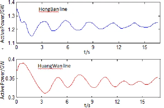
In this section, the identification effect of low frequency oscillation parameters of FSST method for actual grid is tested by the PMU measured data of Sichuan power grid. Before October 2014, the Sichuan power grid was connected with central China power grid through Huangwan line and Hongban line. According to the existing literatures[21], it is found that there exists a 0.32Hz mode between Sichuan power gird and central China power grid, and its damping ratio is often changing under the influence of system operation conditions. In June 19, 2014, 20:44:16, a single-phase grounding short circuit fault occurred in a 500kV high voltage bus in Sichuan power grid[22]. After the failure, the active power oscillation curve of HuangWan line and HongBan line is shown in Fig.6. Huangwan line and HongBan line are key connection between Sichuan power grid and central China grid. So, the existing low frequency oscillation mode can be observed well by their active powers.
[image:8.595.158.444.572.760.2]Therefore, the active power data of two lines is selected as the test signals to analyze the low frequency oscillation, the length of selected signals is 17s. The identification results of frequency and damping ration by FSST are shown as Table 5. The experimental results show that the identification frequency by FSST method is very close to the reference value. So, the FSST method can be used to identify the parameters of the low frequency oscillation in the actual power grid.
Table 4. Identification results of measured PMU data by FSST.
method Oscillation frequency Damping ratio/%
FSST 0.3215 5.227
Summary
In this paper, the Fourier synchrosqueezing transform (FSST) is introduced to identify parameters of low frequency oscillation, and the formulas of amplitude, frequency, attenuation coefficient and damping ratio of oscillation modal component are derived based on the theory of FSST. The experimental results of simulated data and 16-mechine system data show that the FSST method can effectively identify the parameters of low frequency oscillation. Compared with the Prony method, when the low frequency oscillation signal is polluted by noise, the performance of the FSST method is better and the identification result is more accurate. Finally, the identification effect of FSST method is verified by the measured PMU data of Sichuan power grid, and the identification results show that FSST method can be applied to parameter identification of low frequency oscillation in real power grid.
Acknowledgement
This research was financially supported by National Natural Science Fund(No.61671338, 51877161, 51774219), fund from Hubei Province Key Laboratory of Intelligent Information Processing and Real-time Industrial System (Wuhan University of Science and Technology) (znxx2018QN04, znxx2018QN01), fund from Hubei Province Key Laboratory of Systems Science in Metallurgical Process(Wuhan University of Science and Technology(Y201709), and Funded By Open Research Fund Program of Key Laboratory of Digital Mapping and Land Information Application Engineering, NASG(No. GCWD201805)
References
[1] R.W. Wies, J. W. Pierre, D.J. Trudnowski, Use of ARMA block processing for estimating stationary low frequency electromechanical modes of power systems, IEEE Trans on Power Systems. 18(2013)167-182.
[2] S.A. Nezam Sarmadi, V. Venkatasubramanian, Electromechanical mode estimation using recursive adaptive stochastic subspace identification, IEEE Transactions on Power Systems. 29(2014) 349-358.
[3] Ma Jin, Zhang Pu, Fu Hongjun, et al, Application of phasor measurement unit on locating disturbance source for low-frequency oscillation, IEEE Transactions on Smart Grid. 1(2010) 340-346.
[4] D. Kopse, U. Rudez, R. Mihalic, Applying a wide-area measurement system to validate the dynamic model of a part of European power system, Electric Power Systems Research.119 (2015)1-10.
[6] P.W. Darshana, D.A. Udaya, N. Krish. Identification of dominant low-frequency modes in ring-down oscillations using multiple Prony models, IET Generation Transmission & Distribibution. 9(2015)2206-2214.
[7] J. Zygarlicki, M. Zygarlicka, J. Mroczka, et al, A reduced Prony’s method in power quality analysis parameters selection, IEEE Trans on Power Delivery. 25(2010) 979-986.
[8] A. H. Seyyed, A. Nima, H.V. Mohammad, A fourier based wavelet approach using Heisenberg’s uncertainty principle and shannon’s entropy criterion to monitor power system small signal oscillations, IEEE Transactions on Power Systems. 30(2015) 3314-3325.
[9] M. Jonsson, M. Begovic, J. Daalder, A new method suitable for real-time generator coherency determination, IEEE Transactions on Power Systems. 19(2004)1473-1482.
[10]N. Senroy, S. Suryanarayanan, P.F. Ribeiro, An improved Hilbert-Huang method for analysis of time-varying waveforms in power quality, IEEE Transactions on Power Systems.22(2007) 1843-1850.
[11]D.S. Laila, A.R. Messina, B.C. Pal, A refined Hilbert-Huang transform with applications to interarea oscillation monitoring, IEEE Trans on Power Systems. 24(2009)610-620.
[12]J.L. Rueda, C.A. Juarez, I. Erlich, Wavelet-based analysis of power system low frequency electromechanical oscillations, IEEE Transactions on Power System. 99(2011) 1-11.
[13]L.J. Rueda, C. A. Juárez, I. Erlich, Wavelet-based analysis of power system low frequency electromechanical oscillations, IEEE Transactions on Power Systems. 26(2011) 1733-1743.
[14]T. Oberlin, S. Meignen, V. Perrier, The Fourier-based synchrosqueezing Transform, 2014 IEEE International Conference on Acoustics, Speech and Signal Processing (ICASSP), (2014) 315–319.
[15]T. Oberlin, S. Meignen, V. Perrier, Second-order synchrosqueezing transform or invertible reassignment? Towards ideal time-frequency representations, IEEE Transactions on Signal Processing. 63(2015)1335-1344.
[16]R. Behera, S. Meignen, T. Oberlin, Theoretical analysis of the second-order synchrosqueezing transform, Applied and Computational Harmonic Analysis. 45(2018)379-404.
[17]D. Iatsenko, V.E.M. Peter, A. Stefanovska, Linear and synchrosqueezed time-frequency representations revisited. Part I: Overview, standards of use, related issues and algorithms, Digital Signal Processing. 42(2015):1-26.
[18]D.H. Pham, S. Meignen, High-order synchrosqueezing transform for multicomponent signals analysis-with an application to gravitational-wave signal, IEEE Transactions on Signal Processing. 65(2017)3168-3178.
[19]Y. Guo, Z. Fang, X. Chen, A new improved synchrosqueezing transform based on adaptive short time fourier transform, IEEE Far East Forum on Nondestructive Evaluation/testing. (2014)329-334.
[20]G. Rogers, Power system oscillation, Boston, Kluwer, 2000.
[21]L.J. Ding, B. Wang Biao, H.Zhang, et al, Research on stability control and grid structure optimization of UHV AC/DC power transmission system.Chengdu Sichuan Electric Power Research Institute of State Grid Corporation of China, 2013.