Open Access
BMC Musculoskeletal Disorders2002,
3 x
Research article
Biomechanical evaluation of immediate stability with rectangular
versus cylindrical interbody cages in stabilization of the lumbar
spine
Dilip K Sengupta*
1
, SMH Mehdian
2
, Robert C Mulholland
2
, John K Webb
2
and Donna D Ohnmeiss
3
Address: 1William Beaumont Hospital, Royal Oak, MI, USA, 2Center for Spinal Studies and Surgery, Queen's Medical Center, University Hospital
Nottingham, Nottingham, UK and 3Texas Health Research Institute, Plano, Texas, USA
E-mail: Dilip K Sengupta* - [email protected]; SMH Mehdian - [email protected]; Robert C Mulholland - [email protected]; John K Webb - [email protected]; Donna D Ohnmeiss - [email protected]
*Corresponding author
Abstract
Background: Recent cadaver studies show stability against axial rotation with a cylindrical cage is marginally superior to a rectangular cage. The purpose of this biomechanical study in cadaver spine was to evaluate the stability of a new rectangular titanium cage design, which has teeth similar to the threads of cylindrical cages to engage the endplates.
Methods: Ten motion segments (five L2-3, five L4-5) were tested. From each cadaver spine, one motion segment was fixed with a pair of cylindrical cages (BAK, Sulzer Medica) and the other with paired rectangular cages (Rotafix, Corin Spinal). Each specimen was tested in an unconstrained state, after cage introduction and after additional posterior translaminar screw fixation. The range of motion (ROM) in flexion-extension, lateral bending, and rotation was tested in a materials testing machine, with +/- 5 Nm cyclical load over 10 sec per cycle; data from the third cycle was captured for analysis.
Results: ROM in all directions was significantly reduced (p < 0.05) with both types of cages. There was no significant difference in reduction of ROM in flexion-extension (p = 0.6) and rotation (p = 0.92) between the two cage groups, but stability in lateral bending was marginally superior with the rectangular cages (p = 0.11). Additional posterior fixation further reduced the ROM significantly (p < 0.05) in most directions in both cage groups, but did not show any difference between the cage groups.
Conclusions: There was no significant difference in immediate stability in any direction between the threaded cylindrical cage and the new design of the rectangular cage with endplate teeth.
Background
Various designs of interbody fusion cages have been
de-veloped over the last few years for fusion of the lumbar spine. Interbody fusion cage provide structural support as
Published: 3 October 2002
BMC Musculoskeletal Disorders 2002, 3:23
Received: 11 April 2002 Accepted: 3 October 2002
This article is available from: http://www.biomedcentral.com/1471-2474/3/23
well as restore original disc height to open the interverte-bral foramen. Use of tricortical iliac crest allograft in ante-rior or posteante-rior lumbar interbody fusion (ALIF or PLIF) tends to collapse over time, regardless of additional poste-rior fixation [1,2].
The type of surgical technique and approach are depend-ent on the design of the cage. The single large interbody implants e.g., SynCage® (STRATEC Medical Ltd. Welwin
Garden City, UK) or Femoral Ring Allografts are used only for anterior interbody fusion by open approach. The smaller implants may be cylindrical or rectangular and are normally used in pairs. The cylindrical threaded interbody cages (BAK; Sulzer Spine-Tech Inc, Minneapolis, Minne-sota and Ray TFC; Surgical Dynamics Inc, Concord, Cali-fornia) can be used for anterior or posterior interbody fusion and may be introduced by open or laparoscopic technique. The paired rectangular implants e.g., Brantigan carbon-fibre cage (DePuy-Acromed Corporation, Cleve-land, Ohio) or Contact® titanium porous cages with
smooth surface (Stratec Ltd. Welwin Garden City, UK) can be used for either ALIF or PLIF procedures by an open ap-proach only. Rectangular cages are not normally recom-mended for laparascopic insertion.
The immediate three-dimensional stability depends on the cage design. In a study on calf and pig spine, two cy-lindrical implants were found to be more stable than one [3]. Lund et al [4] evaluated immediate stability with a rectangular porous titanium cage (Contact® cage), a
rec-tangular carbon-fibre cage(Brantigan cage), and a cylin-drical threaded titanium cage (Ray TFC) on cadaver spine. They found no significant difference in stabilizing poten-tial of the three cage designs, but the cylindrical cage pro-vided a marginally greater stability against axial rotation compared to the rectangular cages, which offered no sta-bility at all against rotation. The Ray TFC cylindrical cages are designed to engage into the end-plate, where as the rectangular Contact® cages have smooth surface, designed
to fit the endplate contours.
The purpose of this study is to evaluate the immediate sta-bility in lumbar spine after fixation with a new design of rectangular titanium porous cage, which has teeth to en-gage into the endplate, and to compare it with a common-ly used cylindrical cage (BAK).
Methods
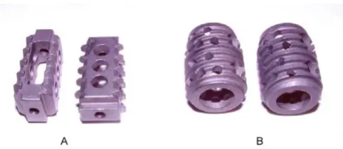
The rectangular cage design
The newly designed rectangular cage (Fig 1) (made by Corin Spinal, Gloucestershire, UK) had a tapered rectan-gular design to restore the lumbar lordosis. The large cen-tral cavity allowed adequate space for packing large amount of cancellous bone graft inside the cage. The teeth on the superior and inferior surfaces were designed to
en-gage into the endplate to provide additional stability. The cages were designed to be used in pair at each level, and could be used for either ALIF or PLIF procedures. The rec-tangular cage was inserted by its smaller diameter into the disc space, and then rotated by right angle to engage its teeth into the endplate, and to align the longer diameter of the cages cranio-caudally.
Specimen preparation
Ten functional spinal units (FSU; five L2-L3, five L4-L5) of human cadaver lumbar spine from 5 subjects (3 male, 2 female) were tested. The donors had a mean age of 76.4 years (range, 68 – 82 years). X-ray and bone densitometry were done to rule out any metastatic or metabolic bone disease. Varying degrees of degenerative changes were found in all of them. From the same cadaver spine one FSU was tested with the rectangular cages and the other with the cylindrical cages. The specimens were stored at -20°C until the 48 hours before testing.
On the day before testing the thawed specimens were stripped carefully all the soft tissues leaving the ligaments and joint capsules intact. Specimens were then potted with plaster of Paris in aluminium pots of the loading jig. To improve anchorage, screws were introduced obliquely into the vertebral bodies close to the endplates away from the disc space.
Test protocol
[image:2.612.314.555.85.190.2]Each of the ten specimens was tested for flexibility of the intact spine, after stabilization with a pair of the either rec-tangular (Corin) or cylindrical (BAK) cages and after addi-tional posterior stabilisation with a pair of translaminar facet screws, as described by Montesano and Magerl et al [5]. Five specimens were tested for each type of implant.
Figure 1
The cages were introduced through the anterior aspect, following the manufacturer's guidelines for surgical tech-nique and estimation of desired disc height. Following stabilization with the cage A-P and lateral radiographs were obtained to ensure correct placement of the implants with adequate restoration of the disc height (Fig 2 and 3).
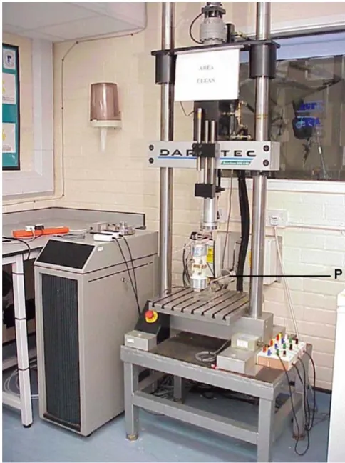
Measurement of flexibility
Flexibility was tested in a servo-hydraulic material-testing machine (Dartec Ltd., Stourbridge, UK) (Fig 4). Special loading jig of similar design as described by Chiba et al [6] was used for mounting the potted specimens eccentrically in the loading frame, to test the flexion-extension move-ment (Fig 5). The length of the lever arm from the axis of motion was 10 cm. A 50 N of preload was applied with a lever arm of 40 cm in the opposed direction, at the bot-tom end of the specimen (Fig 4). The specimens were ro-tated by 90° in the loading jig for testing the lateral bending movement (Fig 6A and 6B). A bending moment was used to produce flexion-extension and lateral bend-ing by applybend-ing a vertical load to the eccentrically mount-ed specimen through the 10 cm lever arm. A preload of 50 N was applied to a lever arm of 40 cm from the fulcrum, in the opposite direction, at the bottom end of the speci-men, as described by Chiba et al [6]. Two digital
goniom-eters, placed at the junction of the loading frame and the lever arm, measured the angular displacement at the FSU with application of the bending moment.
Axial rotation was tested by mounting the specimens in the centre of the material-testing machine, so that the axis of torsion lies midway between the centre and the poste-rior edge of the vertebral body in the sagittal plane. Tor-sion load was applied directly by a rotary actuator on the machine and the axis of torsion of the specimen was aligned to the centre of the actuator. A 200 N compressive load was applied throughout the tests with the linear ac-tuator.
[image:3.612.312.554.86.410.2]The specimens were loaded with a continuous cyclical bending moment of 5 Nm in either direction, at a con-stant rate of 0.5 Nm per second, for four cycles at a time. The load and angular deformation data were captured
Figure 2
[image:3.612.52.298.88.187.2]Rectangular (Corin) cages inserted from the anterior aspect (as in anterior lumbar interbody fusion). Radiographs con-firmed proper cage position and adequate disc height resto-ration. A. Antero-Posterior view, B. Lateral view
Figure 3
Cylindrical (BAK) cages inserted from the anterior aspect (as in anterior lumbar interbody fusion). Radiograph confirmed proper cage position and adequate disc height restoration. A. Antero-Posterior view, B. Lateral view
A B
A B
Figure 4
The Dartec® (Stourbridge, UK) material testing machine,
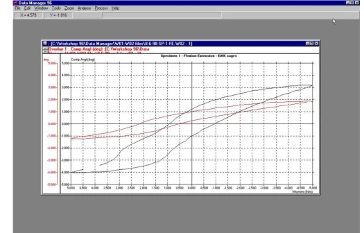
[image:3.612.52.296.252.367.2]from the third cycle. The software (Datamanager 96, Dartec Ltd, Stourbridge, UK) produced the load-deforma-tion curves directly from the captured data (Fig 7).
Statistical methods
Because of the small number of specimens tested in each group, non-parametric methods were used for statistical analysis using SPSS for Windows version 10.0 (SPSS Inc. Chicago, Illinois) statistical software. The range of move-ment (ROM) of each specimen after cage fixation and af-ter additional posaf-terior stabilisation was normalised (ratio of ROM of stabilized to intact specimen) with re-spect to that of the intact FSU. The ROM for the intact specimens between the two cage-groups was compared for any difference using the Mann-Whitney Test. The differ-ence in ROM in the individual cage group between intact specimen, after cage insertion and after additional poste-rior stabilisation were analysed with the related sample Wilcoxon test. The difference in ROM between the cage groups was compared using the Mann-Whitney test. The critical level of significance was 0.05.
Results
[image:4.612.55.296.87.386.2]The ROM for the intact specimen, after cage insertion and after additional posterior stabilisation were recorded from the load-deformation curves (Fig 7). Table 1 and 2 shows the ROM obtained from the specimens tested with the rec-tangular (Corin) and cylindrical (BAK) cages respectively.
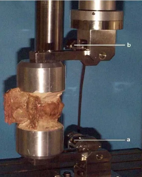
Figure 5
An intact cadaver spine specimen in the eccentric loading jig, mounted for testing flexion-extension movement. a, b are the two digital goniometers, which measure the angular deformation directly. (The preload is not shown in this pic-ture).
Figure 6
The cadaver spine specimens fixed with the cylindrical cages (A) and rectangular cages (B), and mounted in the eccentric load-ing jig rotated 90° to test the lateral bending movements. (The preload is not shown in this picture).
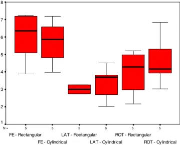
[image:4.612.62.552.493.660.2]The distribution of ROM (median, quartiles and range) of the intact specimens in the two cage groups are shown in Fig 8. There was no significant difference in the ROM of intact specimens between the two groups (Mann-Whitney U test p = 0.602, 0.602, 0.465 for flexion-extension, lateral bending and rotation movements respectively).
Figure 9 and 10 present the distribution of normalised motions (median, quartiles and range) after cage inser-tion and addiinser-tional posterior stabilisainser-tion respectively, for both the cage groups.
Flexion-extension
The range of flexion-extension after insertion of both rec-tangular and cylindrical cages were significantly reduced as compared to that of the intact specimens (p < 0.05 re-lated sample Wilcoxon test). The normalised median flex-ion-extension after stabilization with the rectangular and
the cylindrical cages were 0.438 (range 0.187 – 0.695), and 0.423 (range 0.208 – 0.631) respectively. There was no significant difference (p = 0.602 Mann-Whitney test) between the two cage groups (Fig 9).
Lateral bending
[image:5.612.58.554.109.250.2]The range of lateral bending was significantly reduced af-ter both types of cage insertion (p < 0.05). The normalised median lateral bending after stabilisation with the rectan-gular and the cylindrical cages were 0.365 (range 0.198 – 0.825) and 0.615 (range 0.301 – 1.032) respectively. There was a trend of better stability with the rectangular cages compared to the cylindrical cage group, but the dif-ference was not significant (p = 0.117, Mann-Whitney test), (Fig 9).
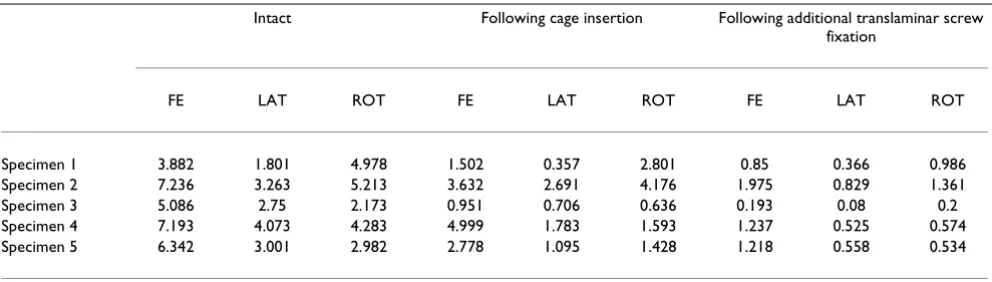
Table 1: ROM in individual specimen in the rectangular cage group. The ROM in degrees in intact specimen, following fixation with the rectangular cage, and following additional posterior translaminar screw fixation.
Intact Following cage insertion Following additional translaminar screw fixation
FE LAT ROT FE LAT ROT FE LAT ROT
Specimen 1 3.882 1.801 4.978 1.502 0.357 2.801 0.85 0.366 0.986
Specimen 2 7.236 3.263 5.213 3.632 2.691 4.176 1.975 0.829 1.361
Specimen 3 5.086 2.75 2.173 0.951 0.706 0.636 0.193 0.08 0.2
Specimen 4 7.193 4.073 4.283 4.999 1.783 1.593 1.237 0.525 0.574
Specimen 5 6.342 3.001 2.982 2.778 1.095 1.428 1.218 0.558 0.534
[image:5.612.57.553.331.468.2]FE-flexion-extension, LAT-lateral bending, ROT-rotation.
Table 2: ROM in individual specimen in the cylindrical cage group. The ROM in degrees in intact specimen, following fixation with the cylindrical cage, and following additional posterior translaminar screw fixation.
Intact Following cage insertion Following additional translaminar screw fixation
FE LAT ROT FE LAT ROT FE LAT ROT
Specimen 1 7.183 4.502 6.827 3.089 2.767 2.635 1.925 1.202 1.318
Specimen 2 4.803 2.691 3.016 0.999 2.223 2.286 1.446 0.689 0.651
Specimen 3 6.581 3.803 5.293 4.153 1.145 2.228 1.283 0.73 0.519
Specimen 4 3.982 2.015 4.168 1.262 1.201 2.384 0.725 0.197 1.096
Specimen 5 5.871 3.692 3.923 2.483 3.81 0.82 1.016 0.609 0.769
Axial rotation
The range of axial rotation was significantly reduced after both types of cage insertion (p < 0.05). The normalised median axial rotation after stabilisation with the rectangu-lar and the cylindrical cages were 0.479 (range 0.293 – 0.801) and 0.421 (range 0.209 – 0.758) respectively. The difference was not significant (p = 0.917, Mann-Whitney test), (Fig 9).
Additional posterior fixation
The ROM after additional posterior fixation with translaminar screws was significantly reduced as com-pared to cage insertion alone for most of the movements for both cage groups (p < 0.05 related sample Wilcoxon test), except in two situations. The range of lateral bending in the rectangular group, and the range of flexion-exten-sion in the cylindrical cage group were only marginally
different following additional posterior stabilization (p = 0.08 for both).
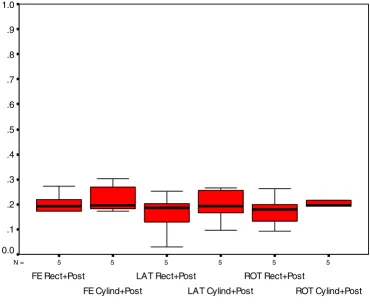
There was no significant difference between the two cage groups, in ROM in any direction, following additional posterior stabilisation (p = 0.465 for all the movements, Mann-Whitney test), (Fig 10).
Discussion
[image:6.612.36.561.87.423.2]With increasing popularity in the use of cages for spinal fusion, a large number of cages have been introduced dur-ing the last decade, with a corresponddur-ing number of cage biomechanics studies reported in the recent literature. These include assessment of individual cages [3,7–10], comparison of stability with different cage designs [4,10– 13], the effect of direction of cage insertion [13–16], the effect of additional posterior fixation [10,13,17], and lit-erature reviews on biomechanical studies [18,19]. The
Figure 7
Example of range of motion and hysteresis produced from an intact specimen (black), and after BAK cage insertion (red), with
cage in this study was designed to combine the advantages of a rectangular shape, freedom of anterior or posterior in-sertion, and to improve the rotational stability with teeth that engage the vertebral endplate.
Effect of cage insertion
In the present study, both cage designs significantly re-duced movement in all directions when compared to that of intact specimens. In flexion-extension the stability was almost identical for both types of cages investigated. This is consistent with reports of earlier investigators [4,11,13,16].
Lund et al [4] noted inability of two types of rectangular cages (Brantigan carbon fiber, and Contact®) to resist axial
rotation. In fact ROM in axial rotation significantly in-creased. In contrast, the cylindrical cages (Ray TFC) pro-vided a marginally superior stability against axial rotation
compared to the control. Tsantrizos et al [11] observed su-perior stability with a ScrewCage compared to the other cage designs. The superior stability to rotation with screw-in cages may be related to the screw threads engagscrew-ing the endplate. In a biomechanical study on cadaver spine, us-ing BAK cages and translaminar screw, Rathonyi et al [17] observed very poor rotational stability in specimens with poor endplate contact. They concluded that the quality of endplate contact may be the most important factor for ax-ial rotational stability. This may explain the poor rotation-al stability with rectangular cages as observed by Lund et al [4] The Contact® cages have smooth surfaces to fit the
[image:7.612.138.498.122.415.2]endplate contour. The Brantigan carbon fiber cages have serrations on their cranial and caudal surface, which pre-vent cage migration but they are not designed to cut into the endplate.
Figure 8
The distribution of range of motion in degrees (median, quartiles and range) of the intact specimens in the two groups fixed with rectangular and cylindrical cages. There was no significant difference between the two cage groups in flexion-extension (FE), lateral bending (LAT), and rotation (ROT).
5 5
5 5
5 5
N =
ROT - Cylindrical ROT - Rectangular
LAT - Cylindrical LAT - Rectangular
FE - Cylindrical FE - Rectangular
8
7
6
5
4
3
2
In our study, insertion of the rectangular cages (Corin) in-creased the rotational stability compared to the control, and the stability was comparable to that with the cylindri-cal (BAK) cages. This may be the effect of the teeth in these rectangular cages engaging into the endplates.
Both Lund et al [4] and Tsantrizos et al [16] observed no difference in lateral bending stability between the cylin-drical and rectangular cage constructs. In our study rectan-gular cages produced a marginally superior stability in lateral bending motion (p = 0.117) compared to the cylin-drical cage constructs. Although the difference was not sta-tistically significant, this may indicate a small advantage of a rectangular over a cylindrical shape. Theoretically, there is a possibility of side to side rocking movement of
the vertebra over the cylindrical cages inserted in sagittal plane.
Effect of additional posterior stabilization
Posterior stabilization with translaminar screws was de-scribed by Montesano and Magerl et al [5]. Although the stability achieved by stand-alone translaminar or transfa-cetal screw fixation is less rigid compared to pedicle screw-rod instrumentations [20], most investigators suggested that translaminar screws provide sufficient stability in all directions, when combined with anterior column support [17,21].
[image:8.612.113.490.131.431.2]Most studies suggest that supplemental posterior fixation using pedicle screw-rod construct improves stability in all
Figure 9
The distribution of normalized range of motion (median, quartiles and range) following cage insertion. (The ROM of intact motion segment is = 1). There was no significant difference between the two cage groups in flexion-extension (FE) and rota-tion (ROT). Although there was a trend of better stability in lateral bending (LAT) with rectangular cages, the difference was not significant.
5 5
5 5
5 5
N =
ROT - Cylindrical ROT - Rectangular
LAT - Cylindrical LAT - Rectangular
FE - Cylindrical FE - Rectangular
1.2
1.0
.8
.6
.4
.2
direction, and also levels off any difference in stability be-tween stand alone interbody implant constructs [4,16]. In a cadaver spine study Rathonyi et al [17] reported that stand alone BAK cages failed to provide stability in exten-sion and axial rotation. However, supplemental translam-inar screw fixation significantly increased stability in both axial rotation and extension. In a similar study Oxland et al [13] reported significant increase in stability with stand-alone cages (BAK and Syncage) in all directions except in extension; addition of translaminar screw fixation signifi-cantly increased the stability in extension.
In the present study additional posterior stabilization with translaminar screw fixation significantly increased the stability in all directions except in two situations. With rectangular cages there was no significant further increase in stability to lateral bending after posterior fixation (p = 0.08). A similar effect was observed with cylindrical cages
where the difference in stability in flexion-extension be-tween the stand-alone cages and additional posterior sta-bilization was not significant (p = 0.08).
Anterior or posterior cage instrumentation
[image:9.612.128.499.116.420.2]Most investigators agree that interbody cages provide good stability in flexion and lateral bending but little or no stability in extension and axial rotation [4,11,13,16,17,19]. The loss of stability in extension and axial rotation may be related to the obligatory damage to the specific anatomical structures needed for cage inser-tion. Stability in extension depends most on the distrac-tion of the anterior annulus and stability in rotadistrac-tion depends primarily on the integrity of the facet joints. It may be anticipated that with anterior cage insertion (AL-IF) damage to the anterior longitudinal ligament and an-nulus will lead to loss of stability in extension. In contrast, with posterior cage insertion (PLIF) damage to the facet
Figure 10
The distribution of normalized range of motion (median, quartiles and range) following cage insertion and additional posterior stabilization with translaminar screws. (The ROM of intact motion segment is = 1). There was no significant difference between the two cage groups in flexion-extension (FE), lateral bending (LAT), and rotation (ROT).
5 5
5 5
5 5
N =
ROT Cylind+Post ROT Rect+Post
LAT Cylind+Post LAT Rect+Post
FE Cylind+Post FE Rect+Post
1.0
.9
.8
.7
.6
.5
.4
.3
.2
.1
joints will lead to greater loss of stability in rotation. The cage diameter for cylindrical cages and cage height in rec-tangular cages (where cage is inserted and rotated 90°) dictates the extent of medial facetectomy needed for cage insertion.
With posterior cage insertion (PLIF) Tsantrizos et al [16] reported marginal changes in extension, but stability in axial rotation decreased significantly, more with Ray TFC than with Contact® cages. Lund et al [4] found increased
range of axial rotation with posterior insertion of both Contact® and Brantigan cages, and no significant change
in extension with any cage design compared to the con-trol.
With anterior cage insertion (ALIF) Oxland et al [13] found no stabilization in extension but significant stabili-zation in axial rotation using BAK cages in cadaver spine. Rathonyi et al [17] found a similar decrease in stability in extension but no change in axial rotation.
Tencer et al [14] evaluated a cylindrical cage (Ray TFC) in different orientations within the interbody space in calf and human cadaver spine. There was no significant differ-ence with the direction of cage insertion except when pos-terior placement damaged facets or lamina. In this case torsional stiffness was reduced. Stiffness achieved with an-terior implantation decreased when the anan-terior annulus was damaged.
The rectangular cage used in the present study is designed for insertion from both an anterior and posterior direc-tion, but was tested for anterior insertion only. We ob-served increased stability in axial rotation, and in flexion-extension in both the cage groups.
Limitations
The principle limitation in this study was the use of a con-strained system for applying load. Rotations were allowed in one axis only, and coupled motions were prevented. It has been described in the literature that a closer estimate of a physiological load-deformation in any specimen may only be obtained by applying pure moment, with six de-grees of freedom, allowing coupled motion [22] However, it is expected that a constrained system would affect the load-deformation and the ROM patterns almost equally, for both the stabilization system. Therefore, a constrained system may not give a true estimate of a physiological ROM but will be good enough to compare two different stabilization systems. The constrained system used here is certainly much simpler, faster, and allows cyclical loading of the specimen, as opposed to the stepwise quasi-static loading often applied during pure moment testing. Addi-tionally, it produced a precise measurement of load-defor-mation curve and ROM on repeat testing on the same
specimen, which helps to identify relatively small differ-ence between the two systems.
The second limitation was that, like many other biome-chanical studies [3,8,11] the flexion-extension ROM was recorded in this study as one composite movement. In practice however, the cage insertion should have a differ-ent effect on flexion as compared to extension. Conse-quently, our study may have missed the lack of stability in extension with the cages. This fact was stressed by Lund et al [4]. The reason behind our method is that we used an eccentric loading jig to apply a continuous cyclical load, to produce flexion-extension movement. The hysteresis curve was directly produced by the software (Datamanag-er 96, Dartec Ltd, Stourbridge, UK) in our exp(Datamanag-erimental setup from a continuous flexion-extension movement. This offered a more sensitive and precise record of the flex-ibility of the spine, which improved the comparison be-tween the two different cage systems.
The other limitation is that our study does not provide the effect on stability with posterior insertion of the rectangu-lar cage. The cage is designed to be rotated 90° after inser-tion requiring medial facetectomy equal to the cranio-caudal height of the cages. Therefore the axial rotation sta-bility observed with the stand-alone cages after anterior insertion may not hold true for their posterior insertion.
Conclusions
1) There was no significant difference in immediate stabil-ity achieved with a standard threaded cylindrical cage and the new rectangular cage with inferior and superior teeth.
2) The rectangular cages alone achieved significant stabil-ity in axial rotation after anterior insertion. It may be pos-sible that the teeth in the new rectangular cages designed to engage the endplates contributed to the improved me-chanical stability in rotation.
3) Additional posterior stabilization increased the stabili-ty for all movements.
Competing interests
No remuneration, financial or otherwise was received for this study from any party. The rectangular interbody cage used in this study was developed by the senior author Mr. SMH Mehdian, in collaboration with The Corin Group, Cirencester, Glcestershire, UK. It has subsequently been made available for clinical use by the same company as Rotafix® intervertebral cage.
Authors' contributions
guidelines and commented on the paper. RCM participat-ed in design of the study and evaluation of the guidelines of biomechanical testing. JKW participated in the design of the study and evaluation of the guidelines. DDO partic-ipated in the design of the study, statistical analysis, and provided feedback on manuscript.
All authors read and approved the final manuscript.
Acknowledgements
We like to thank Dr. Jeffrey R. McConnell, MD for his assistance in prepar-ing the manuscript of this article.
References
1. Ramani P, Singhania BK: Comparison of settlement of disc height in PLIF with and without metallic implants.In: Proc 7th International ICLFS Meeting; Budapest, Hungary 1995
2. Dennis S, Watkins R, Landaker S, Dillin W, Springer D: Comparison of disc space heights after anterior lumbar interbody fusion.
Spine 1989, 14:876-878
3. Butts M, Kuslich S, Bechtold J: Biomechanical analysis of a new method for spinal interbody fixation.In: Advances in bioengineer-ing (Edited by: Erdman A) New York: The American Society of Mechanical Engineers 1987, 95-96
4. Lund T, Oxland TR, Jost B, Cripton P, Grassmann S, Etter C, Nolte LP: Interbody cage stabilisation in the lumbar spine: biome-chanical evaluation of cage design, posterior instrumenta-tion and bone density.J Bone Joint Surg Br 1998, 80:351-359 5. Montesano PX, Magerl F, Jacobs RR, Jackson RP, Rauschning W:
Translaminar facet joint screws.Orthopedics 1988, 11:1393-1397 6. Chiba M, McLain RF, Yerby SA, Moseley TA, Smith TS, Benson DR: Short-segment pedicle instrumentation. Biomechanical analysis of supplemental hook fixation.Spine 1996, 21:288-294 7. Sandhu HS, Turner S, Kabo JM, Kanim LE, Liu D, Nourparvar A, De-lamarter RB, Dawson EG: Distractive properties of a threaded interbody fusion device. An in vivo model.Spine 1996, 21: 1201-1210
8. Brodke DS, Dick JC, Kunz DN, McCabe R, Zdeblick TA: Posterior lumbar interbody fusion. A biomechanical comparison, in-cluding a new threaded cage.Spine 1997, 22:26-31
9. Brantigan JW, Steffee AD, Geiger JM: A carbon fiber implant to aid interbody lumbar fusion. Mechanical testing.Spine 1991, 16:S277-282
10. Jost B, Cripton PA, Lund T, Oxland TR, Lippuner K, Jaeger P, Nolte LP: Compressive strength of interbody cages in the lumbar spine: the effect of cage shape, posterior instrumentation and bone density.Eur Spine J 1998, 7:132-141
11. Tsantrizos A, Andreou A, Aebi M, Steffen T: Biomechanical stabil-ity of five stand-alone anterior lumbar interbody fusion con-structs.Eur Spine J 2000, 9:14-22
12. Rapoff AJ, Ghanayem AJ, Zdeblick TA: Biomechanical compari-son of posterior lumbar interbody fusion cages.Spine 1997, 22:2375-2379
13. Oxland TR, Hoffer Z, Nydegger T, Rathonyi GC, Nolte LP: A com-parative biomechanical investigation of anterior lumbar in-terbody cages: central and bilateral approaches.J Bone Joint Surg Am 2000, 82:383-393
14. Tencer AF, Hampton D, Eddy S: Biomechanical properties of threaded inserts for lumbar interbody spinal fusion. Spine
1995, 20:2408-2414
15. Hitchon PW, Goel V, Rogge T, Dooris A, Drake J, Torner J: Spinal stability with anterior or posterior ray threaded fusion cag-es.J Neurosurg 2000, 93:102-108
16. Tsantrizos A, Baramki HG, Zeidman S, Steffen T: Segmental stabil-ity and compressive strength of posterior lumbar interbody fusion implants.Spine 2000, 25:1899-1907
17. Rathonyi GC, Oxland TR, Gerich U, Grassmann S, Nolte LP: The role of supplemental translaminar screws in anterior lumbar interbody fixation: a biomechanical study. Eur Spine J 1998, 7:400-407
18. Weiner BK, Fraser RD: Spine update lumbar interbody cages.
Spine 1998, 23:634-640
19. Oxland TR, Lund T: Biomechanics of stand-alone cages and cages in combination with posterior fixation: a literature re-view.Eur Spine J 2000, 9(Suppl 1):S95-101
20. Guyer DW, Yuan HA, Werner FW, Frederickson BE, Murphy D: Bi-omechanical comparison of seven internal fixation devices for the lumbosacral junction.Spine 1987, 12:569-573
21. Heggeness MH, Esses SI: Translaminar facet joint screw fixation for lumbar and lumbosacral fusion. A clinical and biome-chanical study.Spine 1991, 16:S266-269
22. Panjabi MM: Biomechanical evaluation of spinal fixation devic-es: I. A conceptual framework.Spine 1988, 13:1129-1134
Pre-publication history
The pre-publication history for this paper can be accessed here:
http://www.biomedcentral.com/1471-2474/3/23/prepub
Publish with BioMed Central and every scientist can read your work free of charge
"BioMedcentral will be the most significant development for disseminating the results of biomedical research in our lifetime."
Paul Nurse, Director-General, Imperial Cancer Research Fund
Publish with BMCand your research papers will be:
available free of charge to the entire biomedical community
peer reviewed and published immediately upon acceptance
cited in PubMed and archived on PubMed Central
yours - you keep the copyright
[email protected] Submit your manuscript here:
http://www.biomedcentral.com/manuscript/