2018 3rd International Conference on Information Technology and Industrial Automation (ICITIA 2018) ISBN: 978-1-60595-607-7
Design and Analysis of Pneumatic Driven
Compliant Automatic Slide Device
Yaowu Shen, Jindong Yu, Xuchong Zhang and Xianmin Zhang
ABSTRACT
Based on the deformation principle of flexible hinge, a kind of pneumatic driven flexible automatic slide deviceis designed. First, a theoretical analysis model of the stiffness and strength is established for the stage. Second, the optimal structure parameters are obtained by the optimization method. Further, the design results are validated by the simulation of Finite Element Analysis software. Finally, prototype of stage is manufactured. Calibration of stage is performed, and error of positioning is analyzed based on the experimental results.1
INTRODUCTION
The current technology of daily sampling and microscopic observing of the active sludge in the sewage treatment plant is entirely artificial mode, which is completely relies on the manual producing glass slides, observing and counting, and even cleaning. The microscopic inspection process is tedious and heavy, which is easy to cause visual fatigue and miscount. Thus it is necessary to develop an automatic device, namely an automatic glass slide, which can be used for the active sludge sampling and microscopic observing.
The pneumatic servo system has been applied in automation fields and even military due to its characteristics of non-flammable, non-explosive medium, strong anti-electromagnetic interference and radiation resistance, non-polluting working
1
Yaowu Shen, Guangzhou Nanyang Polytechnic, China Jindong Yu, Guangdong Construction Polytechnic, China
Xuchong Zhang, School of Design, South China University of Technology, China
medium and suitable for working in harsh environment. It has simple structure, low price and is easy to be operated thus has been getting more and more attention. A compliant mechanism is the new type of mechanism that utilizes the compliant deformation of components such as bar, hinge, joint etc. in the mechanism to complete the transfer and transformation of motion, force and energy. Compared with the traditional rigid mechanism, its advantages are mainly shown in two aspects: first of all it has reduced costs because of fewer numbers of parts, shorter assembly time, and simplified manufacturing process. Secondly, it can achieve performance of increasing precision, reliability meanwhile reducing wear, weight and maintenance [1-5].
Thus it is easy to think of designing an air pressure driving flexible automatic glass slide device, which aims to solve the problem of complicated operation, easily leading to cause visual fatigue and miscount by manually produced liquid microscopy glass slide in existing technology. Based on the theory of material mechanics [6-7], the theoretical modeling of the ring hinge is developed, and the calculation formulas of stiffness, strength of the hinge are deduced by which optimized design of the automatic glass slide device is obtained. The static and dynamic analysis of the stage is carried out to test and verify the designing method by using the finite element analysis software, which is accordance of the testing results over the prototype device.
THE DESIGN OF THE AUTOMATIC GLASS SLIDE DEVICE
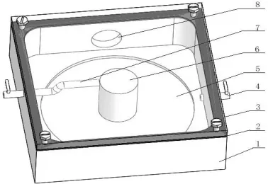
The automatic glass device is mainly composed of seat, sealing gasket and transparent cover, as shown in figure 1. The materials of the base and transparent cover are acrylic sheets, which are polymerization of methyl methenate monomer (MMA), namely PMMA plate organic glass.
1.Seat body 2.Sealing gasket 3.Transparent cover 4.Drainage hole 5.Compliant hinge6.Vertical column 7. Liquid holes to be tested 8.Suction hole
The inner part of the bottom plate is the circular smooth hinge that can drive the lifting and movement of the bottom plate. The cover is opened at the upper end of the opening cavity. The upper surface of the bottom plate is convex with a standing column. Between the upper surface of the standing column and the lower surface of the cover would like to form a gap for the test sampling liquid to be filled. The side wall is set with the exhaust hole connected with an air pump, the injection liquid hole connected with a liquid pump and the drainage hole connected with another liquid pump.
In practice, operation takes several automatic steps to form a thin film used for microscopic observation. First of all, keep closing the drainage pump and starting the injection liquid pump up to the level of the test sample liquid is higher than the surface of the standing column. Then close the injection liquid pump and start the air pump, which will make the body cavity form negative pressure. Under the action of atmospheric pressure the circular hinges will lift the pillar to deflate the narrowing gap between the surfaces of the column and cover plates. Till the test sampling liquid film reached the value of thickness suitable for microscopic observation, the air pump could be closed. Now there is a uniform test sampling liquid film formed between the surfaces of the cover and the pillar which can make microorganism in the liquid free to moving to be observed. Arrive here it is realized for the automatic operation of sampling the test liquid and making the glass slide of microscopic examination.
MODELING OF THE AIR DRIVING SOFT HINGE OF THE DEVICE
[image:3.612.142.507.495.629.2]In the design of automatic glass slide device based on compliant mechanism, the size design of circular hinge is particularly important. On the basis of analyzing the stiffness and strength of the hinge, the size of the hinge is optimized.
Stiffness Analysis of Flexure Hinge
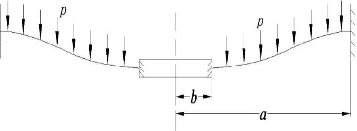
The device is designed by adopting ring compliant hinge, which has the advantages of compact mechanism, easy to process and large deformation. As shown in figure 2, the compliant hinge can be reduced to be series units of the ring hinge. For each unit, of which the periphery is fixed on the rigid inner side of the cavity while the inner end is fixed on the rigid column that can only move up and down without any inclination or torsion. In figure 2, a is the outer radius, b is the inner radius, t is the thickness, and p is the uniform load per unit area of the circular compliant hinge.
The shear force Qr can be obtained by selecting the circular plate of the hinge at any position away from the center r for force analysis and establishing the axial balance formula. 2 2 pr r 2 p r
Qr
(1)
The shear force is introduced into the small deflection differential equation to obtain the bending differential equation of hinge under uniform load.
D r p dr dw r dr d r dr d 2 1 (2)
Where, w is the deflection, ( ) Et
D 2
3
1 12
is the bending stiffness of the material, E is young's elastic modulus of the material, and is poisson's ratio.
The slope of the flexural plane in the radius can be obtained by integrating r twice in a row.
r C r C D r p dr w
d 3 1 2
2 16
(3)
The deflection of the middle surface after bending can be obtained by three consecutive integrals of r.
3 2 2 1 4 4
64 C r C r
C D r p
w
ln
(4)
C1, C2 and C3 are integral constants.
3 2 1 4 1 3 4 64 2 16 C r C D pr w r C D r p dr w d (5)
Where, C1 and C3 are determined by boundary conditions, and corresponding
boundary conditions are:
0 0 dr dw b r w a r , ,
If the boundary condition is substituted into (5), then:
D a p C 8 2 1 64 4 pa C3
(6)
The maximum deflection of hinge at the inner side b is:
2 2 2 64D a bp
w
.
Strength Analysis of Flexure Hinge
In the design of the automatic glass slide device, stress analysis is needed to ensure that the deformation of the hinge is within the elastic deformation range to ensure that no plastic deformation occurs during the automatic glass slide. The stress distribution formula of the upper and lower surface of the hinge is:
1 1 3
3 1 2 2 2 2 2 2 r a t p r a t p 8 r 8 3 3 (7)
Where, r is the radial stress and is the circumferential stress.
The maximum circumferential stress of the hinge appears above and below
the inner edge, while the maximum radial stress r appears above and below the
outer edge.
OPTIMAL DESIGN OF SOFT HINGE
According to the above calculation and analysis, the thickness of hinge t, outer radius a and inner radius b directly affect the performance of automatic glass slide device. With the larger a, the smaller b, the smaller t, the larger stiffness will be reached, as well as the larger w. And the bigger a, the smaller t, the strength is stronger, and also the is bigger. Therefore, these geometric parameters are used as design variables to optimize the design. The purpose of optimization is to make the automatic glass slide device most compliant under the condition of stiffness and strength.
The mathematical model of optimal design of compliant hinge is as follows. Giving the objective function:
2 2
2 64D a bp
w
max
(9)
With constraints:
15 5
200 150
3 1
b a t
(10)
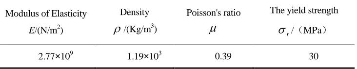
The material selected is acrylic board (PMMA), as shown in table I, and the material performance parameters are given.
[image:6.612.117.483.570.641.2]Optimization results, taking into account manufacturing factors, take t=1mm, a=160mm, b=10mm, pliant hinge w=5mm, at that time, the internal negative pressure is 0.4mpa, =22.4MPa.
TABLE I. MATERIAL PARAMETERS.
Modulus of Elasticity
E/(N/m2)
Density
/(Kg/m3)
Poisson's ratio
The yield strength
r
/(MPa)
Figure 3. Comparison between theoretical stiffness and simulation results.
FINITE ELEMENT SIMULATION ANALYSIS OF SOFT HINGE
Based on the optimization results, a geometric analysis model of automatic glass slide device is established. The static and dynamic analysis of the hinge was carried out by using the finite element analysis software ANSYS. The output displacement and Von Mises stress of the hinge are obtained by static analysis. As shown in figure 3, it is a comparison diagram of theoretical stiffness and simulation results. It can be seen from figure 3 that the theoretical value of flexure hinge stiffness is consistent with the trend of simulation results.
EXPERIMENT AND DATA ANALYSIS
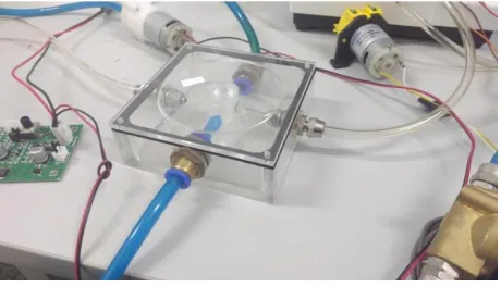
In order to verify the correctness of the design of the automatic glass device, further experiments were carried out after processing the automatic glass device. See figure 4.
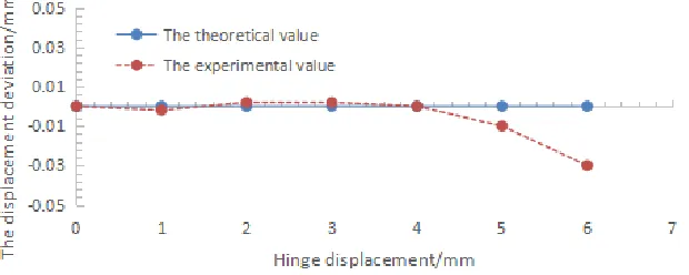
[image:7.612.183.413.529.661.2]Figure 5. Displacement deviation.
The experimental results show that the experimental and theoretical values between the air pressure and the displacement of the hinge are in good agreement.
As shown in figure 5, it is the displacement deviation with air pressure as the target. It can be seen that, the output displacement of compliant hinge has certain deviation at both ends. The main reasons for the error are analyzed as follows:
(1) The micro-machining error of the automatic slide device, especially the machining error of the base of the automatic slide device, affects the stiffness of the compliant hinge, thus affecting the output displacement.
(2) The relationship between the input air pressure of the air pump and the displacement of the compliant hinge is non - linear, and the hysteresis of the air pressure results in a certain error in the output displacement of the compliant hinge.
CONCLUSIONS
An automatic glass slide device based on air pressure drive is designed. Firstly, the mathematical modeling of the automatic glass slide device is carried out to obtain the calculation expression of the stiffness and strength of the platform. On this basis, the structure of the platform is optimized to make the maximum displacement of the platform meet the requirements of strength and stiffness. The correctness of the optimization design is verified by simulation analysis. The prototype of automatic glass slide device was manufactured and the experimental research was carried out. This study provides an effective method for designing automatic glass slide device.
ACKNOWLEDGEMENTS
research result of the 2017 "project of strong innovation school" of Guangzhou Nanyang Polytechnic (NY- 2017cq1cgpy-01).
REFERENCES
1. Xuelin Wang, Yongfei Xiao, Shuhui Bi, et al. Design of test Platform for Robot Flexible Grasping and Grasping Force Tracking Impedance Control[J]. Transactions of the Chinese Society of Agricultural Engineering (Transactions of the CSAE), 2015, 31(1): 58-63.
2. Howell L. Compliant Mechanisms[M]. New York: John Wiley & Sons Press, 2001.
3. Pavlovic N. Compliant Mechanism Design for Realizing of Axial Link Translation [J]. Mechanism and Machine Theory, 2009, 44(5): 1082-1091.
4. Masters N, Howell L. A Three Degree-Freedom Model for Self-Retracting Fully Compliant Bistable Micro Mechanisms[J]. Journal of Mechanical Design, 2005, 127(4): 739-744.
5. Na Li, Tieshi Zhao, Dongbo Sun, et al. Pseudo-Rigid-Body Modeling for Distributed-Compliance Fully Compliant Mechanism[J]. Journal of Mechanical Engineering, 2010, 46(19): 83-88.
6. Yueqing Yu, Qingping Xu. Dynamic Modeling and Characteristic Analysis of Compliant Mechanisms Based on PR Pseudo-Rigid-Body Model [J]. Transactions of the Chinese Society for Agricultural Machinery, 2013, 44(3): 225-229.