2019 2nd International Conference on Informatics, Control and Automation (ICA 2019) ISBN: 978-1-60595-637-4
Online Packaging Method of Fi
lament Cathode for
Intelligent Manufacturing
Ling-hua KONG
1, Yong QIAN
2, Yu-ming CAI
3,
Jing-fang XIE
3and Ding-rong YI
4,*1
School of Mechanical and Automative Engineering, Fujian University of Technology, Fuzhou 350118, China
2
Ningbo Five-Dimensional Inspection Co. Ltd. National Physics Science &Technology Park, No. 228 Jingu North Road. Yinzhou District, Ningbo City, Zhejiang Province, China
3
Minglang Science and Technology Co. Ltd. Jimei District, Xiamen, 361021, China
4
College of Mechanical Engineering and Automation, Huaqiao University, Xiamen 361021, China
*Corresponding author
Keywords: Magnetron cathode, Cathode filament, Tangling and embedding, Online packaging, Sequential to parallel conversion, Parallel queue, Stopping lever, Automatic grabber.
Abstract. It is challenging to automatically package spiral shaped filament cathodes that are widely used in worldwide microwave ovens. The difficulties include a fast packaging speed of over one parts per second and the dexterity required to handle tangling and embedding between spiral filaments’ multiple circles. In order to convert conventional labor intensive packaging lines of filament cathodes into automatic ones, an online fast automatic packaging method is reported. The method converts the fast incoming sequential flow of filament spirals into a batch of twenty-parallel queues with two stopping levers. The proposed method using two levers to release only the front twenty filaments at a time, one from each queue to fill one complete row of the plastic packaging tray. In this way, it speeds up packaging speed twenty times over conventional sequential packaging method. The inner diameter of the queue tube matches the outer diameter of the filament. It is this dimeter matching to eliminate the embedding problem occurred between neighboring filaments. The proposed method uses vibrating brush to decouple tangled filaments. Large number of validating experiments indicate that the proposed method could automatically package 200 filaments spirals within 2 minutes, with positional accuracy of over 97%. Thus, the proposed packaging method could meet the manufacturing requirement of filament cathodes, releasing four labors out of every production line at every work-shift. Further, this method also simultaneously improves the surface quality of the filaments by eliminating scratch caused by their sharp fresh-cutting cross sections.
Introduction
filament cathodes are made in China. This is because this country is rich in rare earth raw materials of tungsten and thorium. The factories find it is challenging to automatically package the spiral shaped filaments. Existing spring spiral packaging method does not satisfy the speed requirement of online packaging of filament cathodes5.
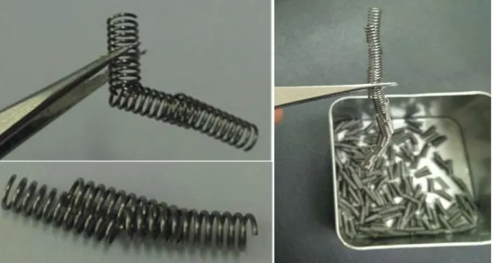
[image:2.595.123.476.250.438.2]The manufacturing of filament spirals includes multiple processes. The first step is to pull the molten thorium tungsten material into a long-wire. Secondly, bend and wound the long-wire into a spiral tube. Thirdly, cut the spiral tube into multiple filament spirals. Fourthly, packaging the filament spirals intro trays. Then the fifth or the last step is quality inspection under a microscope. The typical length of a filament spiral is about 25mm, with outer-circle diameter of about 5mm. The spiral contains about 10 circles of winding filament, with pitch size between two adjacent circles is about 2mm. Since the spirals are cut out of a long-winded tube line, its both ends may either have a round- or sharp-shaped cutting cross-section, depending on the cutting tool.
Figure 1. The enbedding and tangling of spiral-shpaed thorium tungsten filament, which is the key component of a cathode megnetron used in world-wide microwave ovens.
With the advancement of automatic manufacturing of various products, the first three steps of the filament spiral processing lines have been successfully converted from labor-intensive type into semi-automatic ones. With at most one worker per machine. For example, with the spiral cutting process, one worker stands beside each automatic cutting machine to continuously feed it with spiral-like wires. However, for the packaging process, filament spirals produced by each single cutting machine need four workers to do the packaging, since it is challenging to make this process automatic. One problem comes from the fact that they contain multiple circles, causing them enbedding and tangling with each other. Fig. 1 shows some spiral-shaped thorium tungsten filaments used in worldwide microwave ovens. Fig. 1 also illustrates the ways how the spiral-shaped filaments tangling and embedding into each other. This makes it is challenging to automatically separate them into different pits of a packaging tray. Separating them needs dexterity of human fingers with careful eye-hand coordinating. Another problem is the speed of filament coming from the manufacturing line at over one part with a second. Existing
to fulfill all these goals. In a related paper, an automatic quality inspection method is reported separately.
Design Requirements for Automatic Packaging
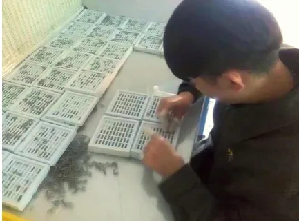
[image:3.595.188.405.294.454.2]The challenge of the packaging process of filament spiral comes from multiple aspects. First, the speed of the cutting process is quick, which is over 60 spirals (typically 68 spirals) over every minute. This is far too fast for any human to pick it up and place it orderly in a tray. Hence, the spirals are piled up in a plastic basket (Fig. 1, right column). This causes a second challenge, i.e., the piling of the filament spiral cause in embedding and tangling of the spirals into each other, making it difficult and time-consuming to separate them. Conventionally, filament spirals produced by one cutting machine usually need about four workers to manually place them in a tidy manner into a plastic tray (Fig.2). Further, the piling of the filament spiral may cause the surface scratched by the sharp-cutting cross section, which have to be removed away from the packaging process. In order to automatic this packaging process with higher efficiency and better quality, the design requirements of the packaging devices include:
Figure 2. Manual packaging of filament spiral into a plastic tray.
① Fast, about to package on average over 60 filament spirals per minute. Use the same existing disposable plastic tray that is conventionally used in the manual packing process, each tray shall contain 200 filament spirals, with 10 rows by 20 columns. The length of the tray is about 25cm, and its width is about 21.5cm. This means about 3 minutes per tray. Leaving sufficient time to move full tray away from and empty tray into the output port of the cutting machine, this means about 2 minutes to package a full tray.
② There may exist unexpected interrupts of the cutting process due to many possible reasons. The major challenge to automatic the packaging process is the required speed. Conventional method using motorized XY stage to move the tray relative to the cutting machine. However, such approach would cause a dilemma between a high moving speed of the tray and accurate placement of the filament spiral into a vacant spot. The reasoning is described as below.
We first theoretically analyze the feasibility of using a conventional XY motorized stage. To sequentially fill in the 200 vacant spots of a tray, the tray needs to travel a distance of 250mmⅹ20 columns +210mm within 2 minutes. The means a maximum speed of about 41.8mm/s if the tray is moving at a constant speed without stop nor acceleration/deacceleration. This speed is far too high to allow the filament spiral to fall into the vacant spot without bumping out of it. The bumping force exerts on the spiral would be 41.8mm/sⅹ1gram)/δt. The contacting time is very short, and hard to measure. However, it is reasonable to estimate that it is of the order of microseconds. Hence, the bumping force would cause the spiral bump and jump out of the tray randomly.
one of its vacant spot is just placed underneath the output port of the cutting machine at the time before the spiral is ready to drop into it. Then deaccelerate to let the spiral drop into the spot. Then accelerate and move the tray again so its next vacant spot is placed underneath the output port of the cutting machine, wait for the next spiral to come. This is repeated ten times to feed the whole row. After one row finishes, move the tray vertically to place the second vacant rows into place. Then continuously feed the second row. However, this approach would not work considering the limited acceleration and de-acceleration of any two-dimensional motorized stage, and the vibration caused by periodic acceleration and de-acceleration of the mechanical system. The feasible packaging speed using the XY motorized stage is typically 22 minutes per tray, which is about 10 times slower than the requirement of 2 minutes per tray.
Hence, a sequential packaging approach is proposed to solve the problem of filling in the 200 vacant spots of the disposable plastic tray within 2 minutes.
Design of the Packaging Device
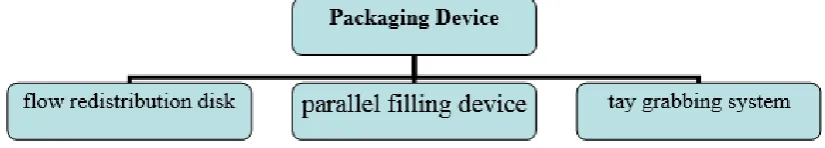
[image:4.595.89.502.347.421.2]The idea is to do parallel packaging by decoupling the tray’s XY two dimensional movements into two one-dimensional movements of different objects. The major componets of the designed parallel packaging device include a flow redistribution disk, parallel filling device, and a tray grabber (Figure 3).
Figure 3. The major components of the packaging device include a flow redistribution disk, a parallel filling device, and a tray grabbing system.
The designed flow redistribution disk is shown in Figure 44a. Its major componets include one fixed entry cup, one rotational arm, and 20 parallel output paths. The entry cup is beneath the output port of the cutting machine. Fast sequential flow of filament spirals coming at a speed of about 70 spirals per minutes from the cutting machine enters the disk via the entry cup. The entry cup shall not be flat, instead, it should be like a deep bowl shape to allow bumpped filament spiral fall back into the cup. Its material should be soft plastics to extend the contacting time between the falling spiral and the cup, in order to reduce the bumping force used to reduce the momentum of the filament down to zero. The rotational arm then bridge the filament to one of the 20 parallel paths. Special attention is needed to guarantee roughlly equal amount of filament move to each of the 20 parallel-paths. This is done by an infrared sensor to detect whether or not an actual filament is moved to a path. The 20 parallel output paths of the redistribution disk are connected to a total of 20 queuing tubes of a parallel-filling device (Figure 4b).
Figure 4. (a) Flow redistribution disk, (b) Parallel-filling device with a motorized releasing mechanism.
The releasing mechanism is rather complex. It contains two motorized stopping levers A and B, placed at a distance of about 25mm away. This distance is adjustable according to the length of the filament to be packaged. The releasing mechanism is placed between the exit end of the parallel queuing tubes and the plastic tray, with the lever B closer to the exit. When the tray is properly placed under the exit of the parallel queuing tube, then a message is sent by the control unit of the packaging system to signal the releasing mechanism to lift up its motorized stopping lever B and keep its lever A down. So when the stopping lever B is lifted, only the first filament spiral of each queuing tubes could be released, blocking the second filament spiral in each queue by lever A. Hence all spirals entering each queue after its second spiral will also be blocked by lever A. Each time when lever B is lifted up, one filament will slide from each of the twenty ques into one vancant spot of the plastic tray, all together twenty queus will fill in the full twenty-collumns in each row of the plastic tray. In such a way, the parallel packaging is achieved.
Once one row of the plastic tray is filled, the motorized stage is controled to move one step forward, then stays there staticaly. The step size of the stage is the distance between two raws of the tray. While the tray is carried by the stage to move forward to place its next raw in position to wait for the next batch of 20 filaments, the releasing mechanism is controlled to put down its lever B in order to close the door of all queues and to simultaneously lift up its lever A. This results in the full stream of filaments within a queue to move one step forward to lever B. The step size of the stream is the length of the filament. Once the forward stepping of the stream of filament is completed, then lever A is controled to put down to block the second filament and every one behind it, while lever B is lifted up so a batch of 20 filaments slide parallely into the raw of the tray, and so on till 10 raws are filled.
[image:5.595.123.475.69.284.2]Figure 5. A plastic tray containg 10 raws by 20 collumns of filament spirals.
Once the 10 raws of a plastic tray are all filled (Figure 5), the motorized stage will first carry the tray to slightly vibrate back and forth to cause filaments that are still on its plateu to fall into the nearby valley. Then carries it back away from the queuing tubes and enter the automatic tray grabbing system (Figure 6). Then vacumed tray grabber will succk it up, move it, and place it on the top of a pile of trays that are full of spirals. The tray grabber will then suck an empty try and carry it to the now empty motoried stage. After receive the empty tray, the motorized stage will then move forward and place the first row of the empty tray underneath the exit of the queuing tubes. Then start the procedure of packaging the next tray.
It takes roughly from half to one minute for the automatic vacummed grabber to replace the full-packaged tray by an empty one. During this process, the cutting machine may keep on working without being interruptted, even though no tray is receiving its output filament spirals. All parts it produces enter the queuing tubes, waiting there till the tray is ready for them to flow in a batched manner into the tray.
Figure 6. The automatic tay grabbing system to replace a full-packaged tray by an empty one. 20 columns
10 rows
pile of trays full of
spirals pile of empty trays
tray grabber
an empty tray being carried motorized stage
[image:6.595.76.522.535.772.2]Evaluating Results
[image:7.595.67.532.213.364.2]The proposed parallel packaging system was prototyped and tested in a filament spiral-manufacturing factory. Twenty trays were packaged with the prototyped device. The experimental results are shown in table 1 below. The time to package one tray is 2 minutes on average, satisfy the design requirement, and matches the manufacturing speed of the cutting machine. The total number of filament spirals put into each tray is 200, thus the accuracy of packaging number is 100% correct. Though there were still occasionally jumped spirals that were not in the expected pits of the tray, the achieved positioning accuracies were all above 97%.
Table 1. Positionging accuracy of the automatic packaging device.
Experiment ID Jumping Failure # Number of spirals Positionging accuracy Experiment ID Jumping Failure # Number of spirals Positionging accuracy
1 2 200 99.0% 11 2 200 99.0%
2 4 200 98.0% 12 0 200 100.0%
3 6 200 97.0% 13 0 200 100.0%
4 2 200 99.0% 14 5 200 97.5%
5 5 200 97.5% 15 4 200 98.0%
6 6 200 97.0% 16 5 200 97.5%
7 4 200 98.0% 17 2 200 99.0%
8 5 200 97.5% 18 3 200 98.5%
9 3 200 98.5% 19 2 200 99.0%
10 0 200 100.0% 20 2 200 99.0%
Summary and Conclusion
An automatic packaging method was proposed and prototyped to simultaneously deal with the problems of high-throughput packaging of spiral shaped filament spirals at a speed of over one part per second, accurate placement in terms of positioning as well as orientation of the spiral spirals, reduce tangling and embedding among filament spirals, and eliminate scratching by their sharp cutting ends. The experimental results indicate that the efficiency of the prototyped system is to package a 200-spiral tray with 2 minutes. Other performance aspects include 100% accuracy concerning the total number of filament spirals per tray, and over 97% position/orientation accuracy. The proposed automatic packaging facilitates the factory to convert its semi-automatic manufacturing lines into full automatic ones, reduce the manual working load of the most labor-intensive packaging process by one order of magnitude. Saving cost while improving its product quality.
Acknowledgement
This research was financially supported the National Natural Science Foundation of China (NSFC) (grant no.51775200). Dr. Linghua Kong was also financially supported by the Digital Fujian Industrial Manufacturing IOT Lab. The authors are grateful to Dr. Ranjith Kumar Kankala for his proof reading of this draft.
References
[1] Bourgioti, C., Chatoupis, K. & Moulopoulos, L. A. Current imaging strategies for the evaluation of uterine cervical cancer. World J Radiol8, 342-354 (2016).
[3] Mitani, T. et al. Noise-reduction effects of oven magnetron with cathode shield on high-voltage input side. Ieee Transactions on Electron Devices 53, 1929-1936, doi:10.1109/ted.2006.878238 (2006).
[4] Li, S., Yan, T., Li, F., Yang, J. & Shi, W. Experimental Study of Millimeter Magnetrons With Cold Cathodes. Ieee Transactions on Plasma Science44, 1386-1390, doi:10.1109/tps.2016.2585644 (2016).