2019 International Conference on Computation and Information Sciences (ICCIS 2019) ISBN: 978-1-60595-644-2
Structural Design of Wire Rope Hoist and
Finite Element Analysis of Drum
Hongxia Wang, Yuying Ji and Dading Chen
ABSTRACT
The motor, drum, drum shaft, rope arrangement mechanism and drive mechanism of the hoist were designed in this paper. The 3d models of the hoist mechanisms were carried out according to the calculation results. And the 3d models of the drum was imported into Hyperworks for the static finite element analysis, which verifies the correctness of the theoretical design and the feasibility of the structure.
1. INTRODUCTION
Hoist is an important part of lifting vertical transport machinery, which is used to lift materials and install equipment together with auxiliary equipment such as derrick, mast and pulley block, etc. Ii is driven by human or mechanical power to complete the hauling work of drum and winding rope. It is mainly electric hoist now.
The paper would carry out following research: 1) determine the overall design scheme,and design the motor, drum, drum shaft and rope arrangement mechanism[1-3]; 2) carry out 3d modeling of the hoist according to the calculation results, and conduct finite element analysis of the drum to verify whether the design meets the use requirements [5].
Hongxia Wang, School of Mechanical Engineering, Hubei University Of Automotive
Technology, Shiyan 442002, China
Yuying Ji, School of Mechanical Engineering, Hubei University Of Automotive Technology, Shiyan 442002, China
2. DESIGN OF MAIN PARTS
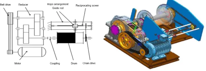
The wire rope hoist designed in this paper is driven by a motor, with rated tension 𝐹𝑒 of 20 KN, drum diameter of 340 mm and rope speed 𝑣𝑒of 15 m/min. The general layout scheme is proposed in Figure 1, the general assembly drawing of the hoist is shown in Figure 2.
Figure 1. General layout of hoist. Figure 2. General assembly drawing.
Although this scheme will occupy a large space in the axial direction, it is more practical in the complex ground environment of engineering buildings and mining areas, and at the same time, the belt transmission plays the role of overload protection. In addition, set up rope arrangement mechanism to make the wire rope easy to uniformly arrange on the drum. It can avoid the phenomenon of tangled winding, and improve the life of wire rope.
2.1 Motor selection
Hoist is not a continuous working machine, it needs to start and brake frequently when working, and the working environment is poor. Therefore, the choice of motor should be compatible with the working environment. Three-phase asynchronous motors are generally used for hoisting equipment.
The selection of motors should be based on their static power:
𝑃𝑔 = 60000𝜂𝐹𝑒𝑣𝑒 = 5.942 KW (1)
Where, 𝜂 is transmission efficiency.
[image:2.595.113.465.225.347.2]motor are chosed, it is working in intermittent cycle system S3. The rotation speed is 705 r/min, and the rated power is 7 KW.
The total transmission ratio of the device is:
𝑖total= 𝑛motor
𝑛drum = 50.36 (2)
According to GB/T 20118-2006, wire rope type is: 6×19 (a)—13—NAT—FC—1570—ZS—102—85.
2.2 Design and strength check of drum
The drum is made of HT250, the width of a layer of rope is 𝐿𝑇, the wall thickness isδ, and the outer ring diameter is𝐷𝑘. The hoist is suitable for small
tonnage working condition, thus:
𝐿𝑇 < 2𝐷 = 2 × 340 = 680𝑚𝑚 (3)
The calculation formula of winding layer number of drum:
n ≤𝐷𝑘−𝐷−2𝑚𝑘
2𝑑𝑆 (4)
Where, 𝑚𝑘 is the safety height to ensure that the rope does not exceed the maximum diameter of the end side plate (no less than 2 times of the rope diameter in two or more layers), 𝑑𝑆 is diameter of wire rope.
Thus𝐷𝑘 ≥ 444𝑚𝑚, then take 𝐷𝑘 as 445 mm.
The wall thickness is
δ = 0.02𝐷 + (6~10) ≈ 12.8~16.8 (5)
To sum up, the design parameters of the drum are: the length of the drum is 500 mm, the diameter of the outer ring of the drum is 445 mm, and the thickness of the drum wall is 17 mm.
As the diameter of the drum is much larger than the wall thickness, the shear stress and bending stress on the drum are ignored. The load on the drum can be simplified to the radial uniformly distributed load 𝛿d, and the
multi-layer winding factor 𝐴2 = 1.4 is introduced. Compressive stress of drum wall is:
Therefore, the compressive strength of the drum meets the requirements.
2.3 Design and strength check of drum shaft
The material of drum shaft is NO.45 steel, which is modulated. The minimum axle diameter can be determined by calculating the limit positions of both ends and considering the influence of keyway:
𝑑 = (1 + 0.05)C√𝑃 𝑛3 ⁄ ≈ 80𝑚𝑚
(7)
Where, P is the transmitted power of the shaft; n is the rotation speed of the shaft; C is the coefficient determined by material and load condition (106 ~ 107).
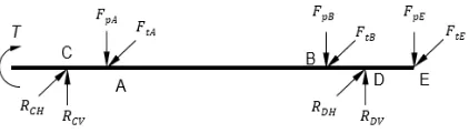
[image:4.595.185.396.425.485.2]According to the knowledge of mechanics of materials [4], the force on the drum shaft is decomposed into the force on the vertical plane and the horizontal plane. The bending composite moment and torsion of the shaft is calculated.
Figure 3.The force analysis diagram of drum shaft.
The stress concentration exists at the section where the keyway is of the drum shaft, which is a dangerous section, and the fatigue strength and static strength of the section are calculated. The safety factor of fatigue strength is satisfied:
𝑆𝑐𝑎 = 𝑆𝜎∙𝑆𝜏 √𝑆𝜎2+𝑆𝜏2
= 2.3 > 𝑆 = 1.5 (8)
So the fatigue strength of the drum shaft meets the requirements. The safety factor of static strength of dangerous section is satisfied:
𝑆𝑆𝑐𝑎 = 𝑆𝑆𝜎∙𝑆𝑆𝜏
√𝑆𝑆𝜎2+𝑆𝑆𝜏24.9 > 𝑆𝑆 = 1.4 (9)
Where, 𝑆𝑆𝜎 is the safety factor of static strength with only normal stress;
𝑆𝑆𝜏 is the safety factor of static strength with onlytorsional shear stress.
Therefore, the static strength of the shaft also meets the requirements.
2.4 Design of rope arrangement mechanism
The use of chain drive has a wide range, it is suitable for the larger center distance and multi-axis mechanism, and it can work in the opening environment. According to the working environment of the wire rope hoist, the chain drive is selected to drive to drum for the rope arrangement mechanism.
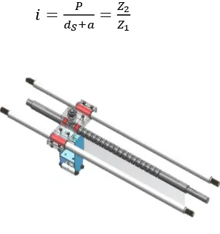
The rope arrangement model is shown in the Figure 4.The relationship between rope arrangement device and chain drive at work is:
𝑖 = 𝑃
𝑑𝑆+𝑎= 𝑍2
[image:5.595.221.375.449.613.2]𝑍1 (10)
Figure 4. The rope arrangement model.
Where, P is the pitch of reciprocating rectangular screw; 𝑍1,𝑍2 are the
working length of the drum. And chain drive can increase the rate of action, so the primary chain drive ratio is 0.25. It can be acquired by calculation that:
𝑃 = (𝑑𝑆+ 𝑎) × 𝑖 = 3.37𝑚𝑚 (11)
And the number of screw threads is :
N =𝑄−10.5𝑖 = 232 (12)
Where, Q is the number of laps of rope arranged in each layer. Two-way reciprocating screw rope arrangement mechanism was selected, which has high bearing capacity and smooth transmission. The drum shaft drives the sprocket wheel, the chain drive makes the two-way reciprocating screw start to rotate, and makes the sliding block on the screw to reciprocate linear motion to evenly arrange the wire rope. To ensure the same linear speed of the drum and the lead screw, there is
𝑉𝑉drum
chain =
𝑑𝑙𝑠
𝑑𝑐 (13)
Where, 𝑑𝑙𝑠 is the diameter of the lead screw; 𝑑𝑐 is the dividing circle
diameter of the small sprocket.
Then linear velocity of the lead screw is:
𝑉ls = 60×1000𝜋𝑑𝑙𝑠𝑛𝑙𝑠 ≈ 𝑉drum (14)
The linear velocity of the drum and the lead screw is approximately equal, so the sprocket wheel is designed reasonably. In order to guarantee linear speed of transmission ratio between the drum and screw shaft, it should also bsatisfied:
𝑖chain= 𝑛𝑁= 0.25 (15)
Where, 𝑛 is the winding number of wire rope. Total stroke of two-way lead screw is as:
In order to prevent the end of screw from sticking, the end arc is adopted to meet the needs of the transition process.
3. FINITE ELEMENT ANALYSIS OF DRUM
The established 3d model of the drum was imported into Hyperworks, and the drum finite element model was established by using free meshing, the number of elements is 1078,332. The drum is made of cast iron HT250, and the material properties are: elastic modulus is 138 GPa, Poisson's ratio is 0.156, and the density is 7,280kg/𝑚3.
The radial uniformly distributed load which is 12.2 MPa (section 2.1) is applied on the working surface of the drum. And the static analysis of the drum is carried out by constraining the bearing holes at both ends of the drum.
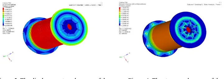
[image:7.595.117.477.353.481.2]The displacement andthe stress of the drum are shown as follows.
Figure 5. The displacement nephogram of the
drum.
Figure 6. The stress nephogram of the
drum.
According to Figure 5 and 6, the maximum deformation of the drum is 0.162mm, which occurs on the outer surface of the drum. Ignoring the stress concentration caused by bolt holes, the maximum stress of the element node of the drum is 145.2MPa, which occurs on the inner surface of the drum. So the drum meets the requirements of strength. The allowable stress of the cast iron is:
4. CONCLUSIONS
Through the design and calculation of main mechanism of the hoist, the 3d model of each part and the assembly model of the hoist are established. The static finite element analysis of the drum and the shaft which are the main working members of the hoist is carried out. The results show that the drum meets the requirements of strength, and it verifies the correctness of the theoretical design and the feasibility of the structure.
ACKNOWLEDGEMENTS
This work was supported by the Hubei Province Education and Science (2018GB030); Innovation Project of Graduate Education (Y2018202); the Natural Science Fund of Hubei Province (2017CFB741); the Foundation o f Hubei Ministry of Education (B2016089); the items of educational research of Hubei Automotive Industries Institute (JX201618) and (2019JXXY12).
REFERENCES
1. Lianggui Pu, Minggang Ji. 2006. “Design of Machiner,”China Higher Education Press.
2. Bangchun Wen. 2010. “Machine Design Handbook,” Machine Press.
3. Zongze Wu, Jiansheng Xian, Xiaoming Yang. 2018. “Concise Mechanical Design Manual,”
China Electric Power Press.
4. Hongwen Liu. 2011. “Material Mechanics,” China Higher Education Press.
5. Jialian Shi, Zhanzhong Yu. 2010. “Finite element analysis of the strength of the interior
transmission mechanism of the hoist drums,” Machinery Design & Manufacture,
(12):203-205.
6. Xiaoming Wang, Shoudong Ni, Peng Cheng. 2014. “The structure design and optimization
of a windlass,” Manufacturing Automation, 36(15):113-115.
7. Huahao Chen. 2003. “Analysis the force and optimization design for the main shaft
structure of the large mine hoister,” Taiyuan University of Technology.
8. Bangjian Ding, Lei Hong, Guohua Jiang. 2016. “Technology and design of drum steel
wire rope winding rope,” Construction Mechanization, 37(08):34-37.
9. Tawanda Mushiri, Milton Jirivengwa, Charles Mbohwa. 2017 “Design of a Hoisting
System for a Small Scale Mine,” Procedia Manufacturing, 8.
10.Qing Huang, Zhi Li, Hongqian Xue. 2018. “Multi-body dynamics co-simulation of