5th International Scientific and Business Conference—Future Engineering 2019 ISBN: 978-1-60595-632-9
Development of Laser Cutting Technology
with High Quality of the Cut Surface
Robert Sołtysiak
1, Agnieszka Sołtysiak
1and Piotr Wasilewski
2ABSTRACT
This paper describes the development of thermal cutting technology aimed at the achievement of the best possible quality class in order to obtain smooth, aesthetic edges. The technology has been developed for two different types of materials: S235JR steel grade and AW-5754 aluminium alloy. The main objective of the developed technology is to eliminate the additional mechanical treatment of the surface following the laser cutting and to allow the classification of the obtained surfaces (without additional measurements) to the appropriate quality class defined by the ISO 9013 standard.
Keywords: laser cutting, surface accuracy, cutting technology
INTRODUCTION
Laser technology was applied for the first time for cutting of steel sheets using a CO2 laser. It took place in 1967 [1]. Thanks to advancements in the design of laser
devices, laser cutting technology has become one of the basic technologies of cutting engineering materials [2]. CO2 lasers have been used for a long time for laser
cutting, but recently, fibre lasers have become more and more popular[3, 4].
Fibre optic lasers are characterized by a high quality laser beam. The BPP (Beam Parameter Product) value does not increase up to the cutting power value of 2 kW (i.e. the quality of the laser beam does not deteriorate). The BPP increases (the laser beam quality deteriorates) only when cutting with power greater than 2 kW. [2].
______________
1
UTP University of Science and Technology, al. prof. S. Kaliskiego 7, 85-796 Bydgoszcz, Poland
2Zakład Produkcyjno-Handlowo-Usługowy TEMIROL Mirosław Łachacz, Gutkowo 81A,
Fibre-optic lasers emit waves of a relatively short length (e.g., their wavelength is tenth times shorter as compared to CO2 lasers). Shorter wavelength improves the
absorption coefficient of laser radiation. As a result, it is possible to cut materials such as copper, nickel and its alloys, as well as composite materials such as Kevlar coated sheet metal [2].
Studies available in the professional literature concerning tests on surfaces obtained using various types of lasers demonstrate that the quality of the cut surface depends mainly on the roughness. In the study [5] on the surface quality after cutting with a Nd-YAG laser, it was shown that the surface roughness increases with the increase of the cutting speed.
It also depends on the frequency of the pulse as well as on its length. In other studies [6], the authors observed that the surface roughness after cutting with Slab type CO2 gas lasers was sometimes increasing and sometimes was falling with the
increase of the cutting power. Other researchers [7] determined optimal cutting parameters without roughness measurement.
However, the standard [8] clearly states that the mean height of the profile Rz5 and the value of the perpendicularity tolerance of the surface after cutting “u” are used to qualify the cutting quality. Authors of the paper [9] compared the quality of cutting with a CO2 laser and a fibre laser based, among others, on the standard [8]. It
was demonstrated that greater dimensional quality, better roughness, higher drag (n) quality, and perpendicularity or angularity tolerance (u) were obtained for cutting using a fibre laser.
This paper describes the development of thermal cutting technology aimed at the achievement of the best possible quality class in order to obtain smooth, aesthetic edges. The technology has been developed for two different types of materials: S235JR steel grade and AW-5754 aluminium alloy. The main objective of the developed technology is to eliminate the additional mechanical treatment of the surface following the laser cutting and to allow the classification of the obtained surfaces (without additional measurements) to the appropriate quality class defined by the ISO 9013 standard.
RESEARCH OBJECT
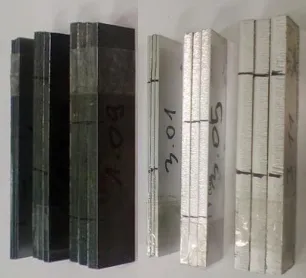
Figure 1. A photograph of sets of samples prepared for testing.
Eighteen samples of 100x20 mm and various thicknesses (2, 4 and 6 mm) were prepared for the main tests. Figure 1 shows photographs of sample packages. Cutting parameters for individual samples are summarized in Table I.
TABLE I. SPECIMEN CUTTING PARAMETERS FOR THE DEVELOPMENT OF HIGH QUALITY CUTTING TECHNOLOGY.
Sample number Cutting speed mm/min Sample number Cutting speed mm/min Sample number Cutting speed mm/min
Thickness 2 mm Thickness 4 mm Thickness 6 mm
S 2 3 5 J R
Laser power = 1.2 kW Laser power = 2 kW Laser power = 2 kW
Focus = 0.2 mm Focus = -1.6 mm Focus = -1.6 mm
Pressure = 6.0 bar Pressure = 0.65 bar Pressure = 0.6 bar
1.01 v1 = 5000 1.05 v1 = 3000 1.09 v1 = 1800
1.02 v2 = 6000 1.06 v2 = 3200 1.10 v2 = 2200
1.03 v3 = 7000 1.07 v3 = 3400 1.11 v3 = 2600
A W 5 7 5 4
Laser power = 2 kW Laser power = 2 kW Laser power = 2 kW
Focus = -1.5 mm Focus = 3.0 mm Focus = 5.5 mm
Pressure = 10.0 bar Pressure = 15.0 bar Pressure = 15.0 bar
3.01 v1 = 6000 3.05 v1 = 2000 3.09 v1 = 840
3.02 v2 = 7000 3.06 v2 = 2500 3.10 v2 = 980
3.03 v3 = 7500 3.07 v3 = 3000 3.11 v3 = 1120
MEASUREMENT OF SURFACE QUALITY AFTER CUTTING OPERATION
According to the [8] standard, the quality of surfaces after thermal cutting should be mainly defined by characteristic values, such as perpendicularity or angularity tolerance “u” and the mean height of the profile “Rz5”. Those parameters were
[image:3.612.91.504.336.542.2]Figure 2. A sample photograph of the roughness measurement.
[image:4.612.100.505.375.681.2]Measurements of the "u" parameter were performed three times in various places on the longer surface of the cut-out specimens. According to the [8] standard, the roughness was measured at a height of 1/3a as seen from the upper surface of the sheet metal. The measurements were performed three times at different spacings. Table II presents the results of the measurements carried out.
TABLE II. RESULTS OF “u” AND “Rz5” MEASUREMENTS.
Thickness 2 mm 4 mm 6 mm
S
2
3
5
J
R
Sample
number 1.01 1.02 1.03 1.05 1.06 1.07 1.09 1.10 1.11
u1, µm 0.014 0.037 0.114 0.096 0.091 0.058 0.073 0.086 0.086
u2, µm 0.029 0.034 0.109 0.095 0.105 0.059 0.073 0.092 0.098
u3, µm 0.023 0.036 0.158 0.098 0.093 0.056 0.046 0.092 0.088
uśr, µm 0.022 0.036 0.127 0.096 0.096 0.058 0.064 0.090 0.091
Rz5_1 4.856 3.451 2.695 2.566 2.251 2.016 64.186 22.884 4.841
Rz5_2 4.543 2.026 1.689 2.670 2.256 1.693 60.458 18.168 6.584
Rz5_3 4.986 3.245 3.248 3.395 2.155 2.111 55.299 24.881 8.526
Rzśr 4.795 2.907 2.544 2.877 2.221 1.940 59.981 21.977 6.650
A
W
5
7
5
4
Sample
number 3.01 3.02 3.03 3.05 3.06 3.07 3.09 3.10 3.11
u1, µm 0.014 0.037 0.114 0.096 0.091 0.058 0.073 0.086 0.086
u2, µm 0.039 0.034 0.109 0.095 0.105 0.059 0.073 0.093 0.098
u3, µm 0.033 0.036 0.158 0.098 0.093 0.056 0.046 0.093 0.088
uśr, µm 0.029 0.036 0.127 0.096 0.096 0.058 0.064 0.091 0.091
Rz5_1 4.856 3.451 3.695 3.566 3.351 3.016 64.186 33.884 4.841
Rz5_2 4.543 3.036 1.689 3.670 3.356 1.693 60.458 18.168 6.584
Rz5_3 4.986 3.345 3.348 3.395 3.155 3.111 55.399 34.881 8.536
SCOPES OF CUTTING QUALITY CLASSIFICATION ACCORDING TO ISO 9013
Table III summarizes the limit values of “u” and “Rz5” specified for SCOPE 1
depending on the thickness of the material subject to cutting. When developing high quality cutting technology, both the “u” perpendicularity tolerance and the average height of the profile (Rz5) as well as the efficiency of the cutting process will be
taken into account.
TABLE III. “u” AND “Rz5” TOLERANCES FOR SCOPE 1 DETERMINED IN ACCORDANCE WITH [8].
SELECTION OF HIGH QUALITY SURFACE CUTTING TECHNOLOGY
While selecting the cutting technology, the data obtained during the tests presented in Table 2 were analysed. Great emphasis was also put on the relatively high efficiency of the cutting process, trying to select the highest cutting speed while maintaining high quality falling within SCOPE 1 (according to Table 3) for both “u” and “Rz5”. A graphic illustration of the results is shown in Figures 3 and 5 for
S235JR steel grade and AW 5754 aluminium alloy, respectively. Vertical dashed lines in the presented graphs indicate the end of SCOPE 1 defined by the [8] standard. This scope, as shown in Table 3, depends on the thickness of the material being cut. The colours of the presented SCOPES marked by dotted vertical lines are consistent with the colours of the applied experimental points for a given material thickness.
For the analysis of the obtained test results, it was assumed that the relationship of “u” and “Rz5” as a function of the cutting speed for a given material thickness is
similar to a straight line. In all the analysed cases, the R2 determination coefficient was higher than or equal to 0.75.
For S235JR Grade Steel
In the case of S235JR grade steel, for the thickness of 2 mm, when cutting at speeds approaching 7 000 mm/min., the “u” value above SCOPE 1 defined by the standard shall be obtained (Fig. 3a). Regarding the “Rz5” value, for the thickness
of 2 mm, all tested parameters fall into SCOPE 1 (Fig. 3b). It was observed that the roughness value defined by the “Rz5” parameter decreases as the speed
increases. However, increased speed for a thickness of 2 and 6 mm can cause deteriorated perpendicularity of the cut.
Scopes of perpendicularity or angularity tolerance „u” Scopes of mean height of the profile „Rz5”
Thickness a, mm 2 4 6 Thickness a, mm 2 4 6
Figure 3. Graphical representation of test results for S235JR steel grade.
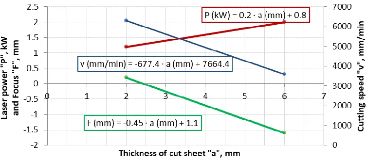
The parameters for the thickness of 2 and 6 mm were used to determine the function defining the parameters for the selection of the technology of cutting with high quality falling within SCOPE 1 of the [8] standard. For a thickness of 2 mm, the optimum cutting speed was chosen from the intersection of the regression line with the dotted line of SCOPE 1. This value amounted to 6310 mm/min. For cutting 6 mm thick sheet metal, the use of lower speeds (below 3500 mm/min) causes a significant deterioration of the surface roughness “Rz5”. However, a reduction of the
cutting speed improves the perpendicularity of the surface obtained after cutting. The use of the highest of the tested speeds for cutting 6 mm thick sheet metal results in achievement of the quality of the surface that qualifies it to SCOPE 1.
Figure 4. Mathematical functions defining the selection of cutting parameters for S235JR steel grade.
For AW 5754 aluminium alloy
Aluminium alloys are materials characterized by a relatively low laser beam energy absorption coefficient. This means that a relatively large portion of the laser beams are reflected from the surface of the aluminium sheet. Cutting of these materials requires higher laser power than in case of cutting, e.g., "black" sheet metal.
The parameters for the thicknesses of 2, 4, and 6 mm were used to determine the function defining the parameters for the selection of the technology of cutting with high quality falling within SCOPE 1 of the [8] standard. For a thickness of 2 mm, the optimum cutting speed was chosen from the intersection of the regression line with the dotted line of SCOPE 1 (Fig. 5a). This value amounted to about 6780 mm/min. For a thickness of 4 mm, the most optimum speed as regards to the surface quality after cutting was the highest tested speed of 3000 mm/min. In the case of cutting 6 mm thick aluminium alloy sheets, the use of the cutting speed up to about 870 mm/min will result in the qualification of perpendicular tolerance to SCOPE 1. However, at this speed, Rz5 roughness will exceed SCOPE 1 (Fig. 5a). On the other
hand, a cutting speed of above 1075 mm/min (Fig. 5b) will result in a cutting surface that can be qualified to SCOPE 1 in terms of the “Rz5” roughness value. However,
Figure 5. Graphical representation of test results for AW 5754 aluminium alloy.
Figure 6. Mathematical functions defining the selection of cutting parameters for AW 5754 aluminium alloy.
SUMMARY
After the tests, it was noticed that, for a given sheet thickness, the “Rz5”
roughness value is generally reduced with the increase of the speed. On the other hand, in most cases, an increase in the cutting speed results in an increase in the “u” tolerance value. In order to select the technology ensuring a high quality surface, it is worth determining which parameter—“u” or “Rz5”—is more important when it
comes to the quality of the surface after the cutting process.
This paper provides a method of developing a cutting technology that allows one to obtain high quality of cutting surfaces for two types of materials: S235JR and AW 5754. Within the framework of this study, mathematical functions have been developed that enable the selection of laser cutting parameters depending on the type of material being cut as well as its thickness. By integrating these mathematical functions with a laser cutting equipment, an automated system can be created that provides tangible benefits leading to development of a reproducible cutting technology characterized by high surface quality (corresponding to SCOPE 1 according to the [8] standard) both in terms of the perpendicularity of the surface after cutting “u” and surface roughness expressed by “Rz5.”
REFERENCES
1. Houldcroft, P. 1967. "Gas-jet laser cutting", British Welding Journal, p. 443.
2. Klimpel, A. 2012. Technologie laserowe. Spawanie, napawanie, stopowanie, obróbka cieplna i
cięcie. Gliwice: Wydawnictwo Politechniki Świętokrzyskiej.
3. Mahrle, A, M. Lütke, and E. Beyer. 2010. "Fibre laser cutting: Beam absorption characteristics and gas-free remote cutting", Proceedings of the Institution of Mechanical Engineers, Part C:
Journal of Mechanical Engineering Science, 224: 1007–1018,
DOI: 10.1243/09544062JMES1747.
4. FIBER LASERS: Fiber lasers: The state of the art. Available from:
https://www.laserfocusworld.com/articles/print/volume-48/issue-04/features/the-state-of-the-art.html [Accessed 27 February 2018].
5. Sharma, A. and V. Yadava. 2012. "Modelling and optimization of cut quality during pulsed Nd: YAG laser cutting of thin Al-alloy sheet for straight profile", Optics & Laser Technology, 44: 159–168. DOI: 10.1016/j.optlastec. 2011.06.012.
6. Riveiro, A, F. Quintero, J. del Val, M. Boutinguiza, R. Comesaña, F. Lusquiños, and J. Pou. 2018. "Laser cutting using off-axial supersonic rectangular nozzles", Precision Engineering, 51: 78–87. DOI: 10.1016/j.precisioneng. 2017.07.013.
7. Rodrigues, G.C., H. Vanhove, and J.R. Duflou. 2014. "Direct Diode Lasers for Industrial Laser Cutting: A Performance Comparison with Conventional Fiber and CO2 Technologies", Physics
Procedia, 56: 901–908. DOI: 10.1016/j.phpro.2014.08.109.
8. ISO 9013. Thermal cutting—Classification of thermal cuts—Geometrical product specification
and quality tolerances.
9. Sołtysiak, R., P. Wasilewski, A. Sołtysiak, et al. 2019. "The analysis of Fiber and CO2 laser