STUDY OF STRUCTURAL PROPERTIES OF MULTILAYER ZNS
THIN FILMS
Jitendra singh1,Pushpendra Singh2,Kapil Sirohi3,Shekher Singh4
1
Dept.of Physics,K.G.K.(P.G.)College,Moradabad,(U.P.)India
2
Dept.of Applied Science,TMU, Moradabad,(U.P.)India
3
Dept.of Basic Education, Moradabad,(U.P.)India
4
Dept.of Chemistry,Devta College,Morna,Bijnor(U.P.)India
ABSTRACT
In the present investigation, the films of Zinc Sulphide and Polyaniline have been prepared by
vacuum Evaporation Technique. The growth and characterization of single layer and multilayer
films have been done. In this paper, the study of X-Ray diffraction and SEM of multilayer
ZnS/Polyaniline thin films has been done.
1. Introduction
Conducting polymers have emerged as a very important class of materials because of their
unique electrical, optical and chemical properties leading to the wide range of technological
applications [1]. This class of materials provides tremendous scope for tuning of their electrical
conductivity from semiconducting to metallic regime by way of doping (MacDiarmid and
Epstein 1994; Wessling 1999) [2,3]. The unique properties of conducting polymers not only
provide great scope for their applications but also have led to the development of new models to
explain their observed properties, particularly various mechanisms of charge transport (Kaiser et
al 1995, 1997)[4,5].Among different conducting polymers, conducting polyaniline is the most
extensively studied material due to the ease of synthesis, better environmental and thermal
stabilities and greater scope of playing with chemistry to tailor their properties (Kumar et al 1996)
[6]. However, when they are taken in the composite form their electrical as well as dielectric
properties are altered from those of basic materials. A number of groups have reported studies on
the electrical conductivity and dielectric properties of composites of a variety of conducting
polymers (Yoon et al 1995; Yang et al 1996; Gangopadhyay et al 2001; Murugesan and
Subramanian 2003) [11].It has been shown that the conductivity of these heterogeneous systems
depends on a number of factors such as the concentration of conducting fillers, their shape, size,
orientation and interfacial interaction between filler molecules and host matrix (Kryszewaski
1991; Brosseau et al 2001)[12]. The geometrical shape of the dispersant governs the ability of
conductive network formation which results in large increase in the conductivity (Troung et al
1994)[104]. Also, dispersant/matrix interactions and physical properties of the matrix influence
the agglomeration of the dispersant phase which, in turn, affects the dielectric properties of the
composites. In case of conducting polymers as fillers, the degree of cross-linking between the
polymeric chains also affects the electrical properties in these composites (MacDiarmid and
Epstein 1995). Although the percolation theory has been generally used to explain the behaviour
of electrical conductivity and dielectric properties of conducting polymer composites (Tuncer et
al 2002),[14] but it could not explain very low values of percolation threshold observed in many
of the composite systems of conducting polymers. Wessling (1998) proposed a non-equilibrium
interfacial interactions between conducting polymers and host matrix could explain the
observations of low percolation threshold.
ZnS is the II–VI family semiconductor, has wide band gap (3.65 eV) at room temperature
and large excitation binding energy 60 meV, ZnS is an attractive semiconductor material
especially in electronic and optoelectronic application.The dielectric constant of ZnS (wurtzite
structure) is 8.75 at lower frequencies and 3.8 at higher frequencies. The molecular mass is
81.389 and the melting temperature is 1450 K [].
ZnS was used by Ernest Rutherford and others in the early years of nuclear physics as a
scintillation detector, because it emits light on excitation by x-rays or electron beam, making it
useful for x-ray screens and cathode ray tubes.It also exhibits phosphorescence due to impurities
on illumination with blue or ultraviolet light.
Zinc sulfide, with addition of few ppm of suitable activator, is used as phosphor in many
applications, from cathode ray tubes through x-ray screens to glow in the dark products.When
silver is used as activator, the resulting color is bright blue, with maximum at 450 nm.
Manganese yields an orange-red color at around 590 nm. Copper provides long glow time and
the familiar glow-in-the-dark greenish color. Copper doped zinc sulfide (ZnS+Cu) is also used in
electroluminescent panels .
Zinc sulfide is also used as an infrared optical material, transmitting from visible wavelengths
to over 12 micrometres. It can be used planar as an optical window or shaped into a lens. It is
made as microcrystalline sheets by the synthesis from H2S gas and zinc vapor and sold as FLIR
(Forward Looking IR) grade ZnS in a pale milky yellow visibly opaque form.This material when
hot isostatically pressed (HIPed) can be converted to a water-clear form known as Cleartran
(trademark). Early commercial forms were marketed as Irtran-2 but this designation is now
obsolete. In this paper we have reported XRD, SEM, of the PANI on glass substrate and PANI
on the ZnS thin film.
2. Sample Preparation of ZnS:- Thin films of ZnS have been prepared by vacuum deposition
cleaned glass substrate held at 200°C in a vacuum of 10-5 torr. The substrate was cleaned in
aquaregia washed in distilled water and isopropyl alcohol (IPA). We have used glass substrate
for the preparation of Zinc Sulphide.
3. Sample Preparation of Poly aniline:-Thin film of polyaniline have been prepared by vacuum
evaporation technique, polyaniline is usually prepared by redox polymerization of aniline using
ammonium perdisulphate, (NH4)2 S2O2 as on oxidant. Distilled aniline (0.02 M) is dissolved in
300 ml of pre-cooled HC1 (l.0M) solution, maintained at 0-50°C. A calculated amount of
ammonium perdisulphate, (0.05M) dissolved in 200 ml of HCl (1M), pre-coated to 0-50° C, is
added to the above solution. The dark green precipitate (ppt) resulting from this reaction is
washed with HC1 (l.OM) uptil the green colour disappears. This ppt is further extracted with
terta-hydofuran and NMP (N-Methyl Pyrolidinone) solution by soxhelf extraction and dried to
yield the emeraldine salt. Emeraldine base can be obtained by heating the emeraldine salt with
ammonia solution. Simultaneously, separate salt solution is prepared by dissolving the MX
(M=Metal and X=Halide) in distilled water. The solution is then slowly added to the precooled
polymer solution with constant stirring. The composite is then dried in an oven, at high
temperature, to get the conducting polymer in the powder form. This powder is vacuum
evaporated on to highly cleaned glass substrate as well as metallic substrate.
4. Characterization of PANI and PANI on ZnS Film:-
(i) X-Ray Diffraction.
X-ray diffraction is a very good non destructive technique to confirm and find the structure of a
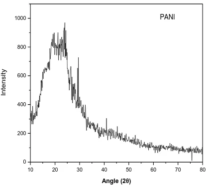
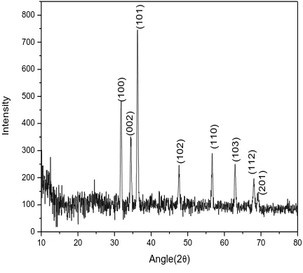
crystal. In figure 1, 2 and 3 the XRD pattern of pure polyaniline, XRD pattern of ZnS and XRD
pattern of PANI on ZnS respectively, has been reported. The XRD pattern of pure Polyaniline in
figure 4.1 shows its amorphous structure because no strong peak has been appeared in XRD
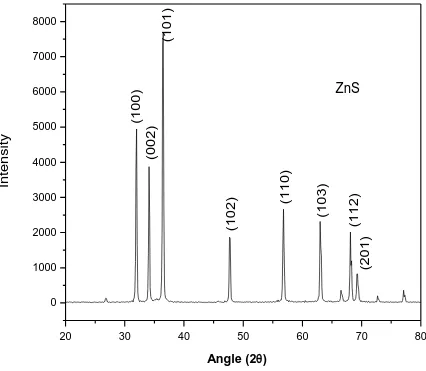
pattern. In the XRD pattern of ZnS [fig 2], strong peaks appear at 2θ=31.5°, 34.3°, 36.1°, 47.4°,
56.4°and 62.9° which corresponds to (100), (002), (101), (102), (110), (103) planes, that
confirms the hexagonal structure of ZnS. The peaks in the XRD patterns show that ZnS film
has a poly crystalline hexagonal wurtzite Crystal structure. The XRD patterns of ZnS in fig. 2
less intensity shows less preferred orientations. In case of PANI on ZnS same preferred
orientation is observed with modified intensity [fig.3]. In addition there is no second phase peak
in XRD patterns for ZnS-composites.
10 20 30 40 50 60 70 80
0 200 400 600 800
1000
PANI
In
te
n
si
ty
[image:5.612.99.513.204.591.2]Angle (2
)
Fig. 1: X-ray Diffraction pattern of PANI
20 30 40 50 60 70 80
0 1000 2000 3000 4000 5000 6000 7000 8000
ZnS
(2 0 1 ) (1 1 2 ) (1 0 3 ) (1 1 0 ) (1 0 2 ) (1 0 1 ) (0 0 2 ) (1 0 0 ) In te n si ty [image:6.612.103.529.136.507.2]Angle (2
)
10 20 30 40 50 60 70 80 0 100 200 300 400 500 600 700 800
(2
0
1
)
(1
1
2
)
(1
0
3
)
(1
1
0
)
(1
0
2
)
(1
0
1
)
(0
0
2
)
(1
0
0
)
In
te
n
si
ty
[image:7.612.82.514.118.507.2]Angle(2
)
(ii) Scanning Electron microscopy (SEM):-
The surface morphology of the material helps in the study of grain growth, orientation of
the grains, compositional and topographical features present on the surface of the material. It is
well known that different phases formed show different morphology when examined with the
scanning electron microscope. From the scanning electron microscope it is possible to determine
the compactness of the material, the particle size and shape etc.
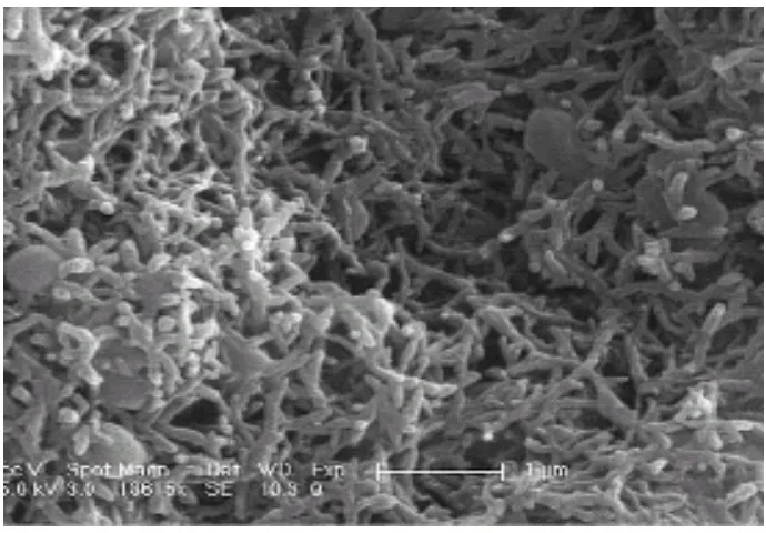
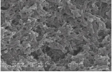
The Scanning Electron micrographs obtained for Polyaniline on glass substrate and
Polyaniline on ZnS thin film has been shown in fig..4 & 5, respectively. The results of the
surface morphology are:
Polyaniline on ZnS shows a uniform morphology like pure Polyaniline film.
It shows some grain like structure due to the ZnS surface. The grains have become more
[image:8.612.134.479.386.626.2]regular and systematic for PANI on ZnS.
Figure 4: Scanning Electron Micrograph of PANI on glass
Figure 5. Scanning Electron Micrograph of PANI on ZnS
5. Result and Disscussion:-
The X-R-D of the sample gives the valuable information about the nature and structure of the
film. The X-R-D pattern indicates the preferred orientation which is important part in structural
characterization. In case of ZnS/glass the preferred crystallographic orientation is observed
corresponding to (101) reflection, while in case of Pani/ZnS/glass same preferred orientation is
observed but with modified intensity. The peaks observed in the XRD pattern shows that ZnS
film has a polycrystalline hexagonal quartzite structure
The prepared films were subjected to scanning electron microscopy analysis to study
surface morphology. The SEM studies of these thin films indicate a large increase in grain size
up to 9 m, it is also observed that the substrate has a strong influence on the surface
morphology of the film. Pani on Zns shows a uniform morphology similar to pure polyaniline
film. It shows some grain like structure due to the ZnS surface. The grains have become more
Refrences:-
1. F. Yakuphanoglu et al., J. Phys. Chem., B, 110, (2006), 16908-16913 2 .Mac. Diarmid A.G.
and Epstein A .,J Synth. Met., 69, (1995), 85.
3. Wessling B., Synth. Met. 102, (1999),1396
4. Kaiser, R. I., & Suits, A. G., Rev. Sci. Instrum., 66, (1995),5405,
5. Kaiser, R. I., Stranges, D., Bevsek, H. M., Lee, Y. T., & Suits, A. G., 6.J. Chem. Phys., 106,
(1997), 4945
7 .Kumar N, Malhotra B.D. and Chandra S., J. Polym. Phys.Ed. (USA) 23, (1985), 57
8 .Yoon C O, Reghu M, Moses D, Cao Y. and Heeger A., J Synth. Met., 26, (1995), 255.
9. Yang J, Hou J, Zhu W, Xu M and Wan M, Synth. Met. 80, (1996),283.
10. Gangopadhyay R and Ghosh G, Synth. Met. 123, (2001), 529.
11.Murugesan R and Subramanian E , Bull. Mater. Sci. 26,(2003), 529.
12.Kryszewaski M., Synth. Met. 45, (1991), 289.
13.Brosseau C, Queffelec P. and Talbot P , J. Appl. Phys. 89, (2001),4532
14.Troung V T, Codd A R and Forsyth M , J. Mater. Sci. 29,(1994), 4331