i
The MOUSE approach:
Mapping Ontologies using UML
for System Engineers
A thesis submitted to the
University of Dublin, Trinity College
for the degree of Doctor of Philosophy
Seung-Hwa Chung
Knowledge and Data Engineering Group, Department of Computer Science,
Trinity College, Dublin
Supervisor: Dr. Declan O’Sullivan Assistant Supervisor: Dr. Wei Tai Industrial Supervisor: Dr. Aidan Boran
i
Declaration
I declare that this thesis has not been submitted as an exercise for a degree at this or any other university and it is entirely my own work.
I agree to deposit this thesis in the University’s open access institutional repository or allow the library to do so on my behalf, subject to Irish Copyright Legislation and Trinity College Library conditions of use and acknowledgement.
ii
Acknowledgements
Above all, I would like to thank to God for giving me this opportunity in my life. During these past four years, I not only had the opportunity to study my chosen field of semantics but also became an academic researcher all the while experiencing a new foreign culture. Studying in Ireland was just as important part of my education as the subject matter itself. I leave Trinity College Dublin with a very valuable education and a lifetime of memories.
I would like to thank my supervisor Prof. Declan O’Sullivan. Without his guidance and support I would not have come this far. I would also like to express my gratitude to Dr. Wei Tai and Dr. John Keeney for their helpful contributions to this research. I also give thanks to Dr. Aidan Boran at Bell Labs Ireland/Alcatel-Lucent for his support and contribution. Additionally, I express my gratitude to my colleagues in KDEG Lab who have always been kind and supportive during my studies.
iii
Abstract
iv
Table of Contents
Declaration ... i
Acknowledgements ... ii
Abstract ... iii
Table of Contents ... iv
Table of Figures ... ix
Table of Tables ... xiii
1 Introduction ... 1
1.1 Motivation ... 1
1.2 Research Question ... 3
1.3 Research Objectives ... 4
1.4 Contribution ... 7
1.5 Thesis Overview ... 8
2 Related Research ... 10
2.1 Ontology mapping categorization ... 11
2.2 Ontology mapping application... 12
2.3 Abstract syntaxes for semantic mapping ... 14
2.3.1 Alignment Format ... 15
2.3.2 EDOAL ... 16
2.3.3 C-OWL ... 18
2.3.4 SSE ... 18
2.3.5 SQWRL ... 19
2.3.6 RIF ... 20
v
2.3.8 UML/OCL ... 23
2.4 Concrete syntaxes for semantic mapping ... 24
2.4.1 Using OWL for semantic mapping ... 25
2.4.2 SWRL ... 26
2.4.3 SPARQL ... 29
2.5 Summary Tables ... 30
3 MOUSE Approach ... 36
3.1 The Core Mapping Types ... 36
3.1.1 Industry Use Case ... 36
3.1.2 Core mapping type example ... 40
3.2 UML Notations Development ... 43
3.3 UML Notations for Ontology Elements ... 46
3.3.1 Ontology Document ... 46
3.3.2 Ontology Class... 47
3.3.3 Ontology Individual ... 48
3.3.4 Ontology Object Property ... 49
3.3.5 Ontology Datatype Property... 50
3.4 UML Notations for Semantic Mappings ... 51
3.4.1 Direct Mapping Type ... 52
3.4.2 Data Range Mapping Type ... 53
3.4.3 Unit Transformation Mapping Type ... 57
3.5 A walked through example ... 62
3.5.1 Direct Mapping ... 64
vi
3.5.3 Unit Transformation Mapping ... 64
3.5.4 Limitation ... 65
4 SDI Tool Development ... 66
4.1 Conversion Process ... 66
4.2 UML to RIF Conversion ... 67
4.2.1 Direct Mapping Type ... 67
4.2.2 Data Range Mapping Type ... 69
4.2.3 Unit Transformation Mapping Type ... 72
4.3 RIF to SPARQL Conversion ... 75
4.4 Implementation ... 79
4.4.1 SDI Tool Modules ... 81
4.4.2 Structured Information Models ... 82
4.5 A walked through example ... 86
5 System Engineers Experiment ... 90
5.1 Experiment Question ... 90
5.2 Experiment Hypothesis ... 90
5.3 Experiment Method ... 91
5.3.1 Participants ... 91
5.3.2 Materials ... 91
5.3.3 Procedure ... 93
5.3.4 Metrics... 94
5.4 Experiment Analysis ... 95
5.4.1 Accuracy ... 96
vii
6 Conclusion ... 109
6.1 Future Works ... 111
REFERENCES ... 113
APPENDIX A Ontologies from the industry use case... 127
Appendix A.1 Femto level ontology - femtoclassifier.owl ... 127
Appendix A.2 Raw level ontology - femtoinstances.owl ... 132
APPENDIX B SDI tool user manual in GUI mode with examples ... 161
Appendix B.1 Example of how to create direct mapping ... 162
Appendix B.2 Example of how to create data range mapping ... 165
Appendix B.3 Example of how to create unit transformation mapping ... 168
Appendix B.4 Example of how to generate mapping outputs ... 171
APPENDIX C SDI tool java archive file usage in command line mode ... 176
Appendix C.1 Usage of “sditool.jar” in command line mode ... 176
Appendix C.2 Composition of the sditool.jar file ... 177
APPENDIX D Mapping design worksheets ... 178
Appendix D.1 Mapping design worksheets for direct mapping type ... 178
Appendix D.2 Mapping design worksheets for data range mapping type... 182
Appendix D.3 Mapping design worksheets for unit transformation mapping type ... 186
APPENDIX E OWL view of initial experiment ontologies in Protégé tool ... 190
Appendix E.1 NC ontology ... 190
Appendix E.2 TR069 ontology ... 191
Appendix E.3 Femto ontology... 192
APPENDIX F OWL view of experiment ontologies in Protégé tool ... 193
viii
Appendix F.2 Target conference ontology ... 194
APPENDIX G Potential mapping candidates in experiment ontologies ... 195
Appendix G.1 Potential mapping candidates in direct mapping type ... 196
Appendix G.2 Potential mapping candidates in data range mapping type ... 197
Appendix G.3 Potential mapping candidates in unit transformation mapping type ... 198
APPENDIX H Brief mapping guide for core mapping types ... 199
Appendix H.1 Brief mapping guide for direct mapping type ... 199
Appendix H.2 Brief mapping guide for data range mapping type ... 200
Appendix H.3 Brief mapping guide for unit transformation mapping type ... 201
APPENDIX I Questionnaire sheets based on the System Usability Scale ... 202
APPENDIX J Experiment overall task sheet ... 204
APPENDIX K Scanned paper result from the experiment ... 205
Appendix K.1 Experiment result from participant ID02 ... 205
Appendix K.2 Experiment result from participant ID13 ... 222
ix
Table of Figures
Figure 2-1 Screenshot of PROMPT by N. F. Noy and M. A. Musen ... 13
Figure 2-2 Screenshot of CoGZ by S. Falconer and M. A. Storey ... 14
Figure 2-3 Alignment Format syntax example for equivalent mapping type ... 15
Figure 2-4 EDOAL syntax example for conditional mapping type ... 17
Figure 2-5 EDOAL syntax example for transformation mapping type ... 17
Figure 2-6 C-OWL syntax example for equivalent mapping type ... 18
Figure 2-7 C-OWL syntax example for subsumption mapping type ... 18
Figure 2-8 SSE syntax example for conditional mapping type ... 19
Figure 2-9 SSE syntax example for transformation mapping type ... 19
Figure 2-10 SQWRL syntax example for conditional mapping type ... 20
Figure 2-11 SQWRL syntax example for transformation mapping type ... 20
Figure 2-12 RIF syntax example for conditional mapping type ... 21
Figure 2-13 RIF syntax example for transformation mapping type ... 21
Figure 2-14 UML/ODM example for ontology class and property ... 22
Figure 2-15 UML/ODM example for ontology datatype property ... 22
Figure 2-16 UML/ODM example for equivalent mapping type ... 23
Figure 2-17 UML/OCL example for conditional mapping type ... 24
Figure 2-18 UML/OCL example for transformation mapping type ... 24
Figure 2-19 OWL syntax example for conditional mapping type ... 26
Figure 2-20 SWRL syntax example for conditional mapping type ... 27
Figure 2-21 SWRL syntax example for transformation mapping type ... 29
x
Figure 2-23 SPARQL syntax example for transformation mapping type ... 30
Figure 2-24 Enumerated and structured type expression ... 34
Figure 3-1 Logical example of the direct mapping type ... 40
Figure 3-2 Logical example of the data range mapping type ... 41
Figure 3-3 Logical example of the unit transformation type ... 42
Figure 3-4 ODM and OCL combined abstract mapping syntax for conditional mapping type ... 44
Figure 3-5 ODM and OCL combined abstract mapping syntax for transformation mapping type ... 45
Figure 3-6 UML notation example for ontology document ... 47
Figure 3-7 UML notation example for ontology class ... 48
Figure 3-8 UML notation example for RDF statement ... 48
Figure 3-9 UML notation example for ontology individual ... 49
Figure 3-10 UML notation example for RDF statement ... 49
Figure 3-11 UML notation example for ontology object property ... 50
Figure 3-12 UML notation example for RDF statement ... 50
Figure 3-13 UML notation example for ontology datatype property ... 51
Figure 3-14 UML notation example for RDF statement ... 51
Figure 3-15 UML notation example for direct mapping type ... 52
Figure 3-16 BNF style syntax expression for data range mapping ... 54
Figure 3-17 UML notation example for data range mapping type with single ontology datatype property in constraint ... 55
xi
xii
Figure 4-9 Translation example of RIF document to SPARQL query for unit transformation
mapping type ... 79
Figure 4-10 SDI tool architecture overview ... 80
Figure 4-11 UML Class diagram for structured UML information model ... 83
Figure 4-12 UML Class diagram for structured RIF information model ... 84
Figure 4-13 UML Class diagram for structured SPARQL information model ... 85
Figure 4-14 ScreenShot of the StarUML graphic user interface ... 86
Figure 4-15 RIF document generated from the UML notations ... 88
Figure 4-16 SPARQL query generated from the RIF document ... 88
Figure 5-1 A sample abstract mapping syntax for ontology mappings from the experiment . 96 Figure 5-2 Auto-generated SPARQL query syntax for the data range mapping ... 97
Figure 5-3 Auto-generated SPARQL query syntax for the unit transformation mapping ... 97
Figure 5-4 A sample mappings on the SDI tool from the experiment ... 101
Figure 5-5 A sample mappings on the SDI tool from the experiment ... 102
Figure 5-6 SUS scores bar graph for the abstract mapping syntax and the tool ... 105
xiii
Table of Tables
xiv
1
1
Introduction
1.1 Motivation
There has always been a need to integrate an increasing set of diverse devices and information systems within an enterprise, e.g. sensors, mobile devices, inventory tracking system, sales system, finance system, human resource system, and so on [Rho 2007]. Typically these devices and information systems are produced by a variety of developers with different data schemas, and information integration of such heterogeneous data is a specialized and brittle process, such that changing the structure and/or addition of new data sources can force an integration redesign [Bernstein 2008]. This heterogeneity makes it difficult for third-party enterprises to manipulate the data of distinct formats and to extract information from the separated data. However, adding semantics to the data can ease these difficulties caused by data heterogeneity [Waters 2009]. For this reason, there has been an increasing effort to embed semantics along with the data in order to ease the integration effort [Duo 2006].
2
relating to the naming process of the ontology entities use different words to name the same entity (synonymy), the same word is used to name different entities (polysemy), words from different languages (multilingualism) and syntactic variations of the same word (different acceptable spellings, abbreviations, use of optional prefixes or suffixes, and so on) [Bouquet 2005][Amrouch 2012].
Ontology heterogeneity typically requires mappings to exchange information in a semantically sound manner [Kalfoglou 2003]. There have been investigations into ontology mapping technologies to resolve the ontology heterogeneity issues that are often encountered during the integration of ontology data from various sources. The existing ontology mapping approaches [Falconer 2007a] usually require mapping practitioners to have a considerable amount of expertise in knowledge engineering in order to perform the mapping process, and ontology mappings are often performed by knowledge engineers. Hence in most of the current situations, a mapping practitioner also needs to be a knowledge engineer. In this research, it is argued that performing a semantic data integration task by system engineers such as telecommunications system engineers that are considered domain experts is more realistic because of the complexity in designing semantic mappings for non-trivial cases in the system. However, since the creation of ontology mappings requires considerable effort [Cruz 2012] and considerable amount of expertise in knowledge engineering [Falconer 2007b], it is understandable that not all the system engineers are able to perform semantic data integration tasks. The research presented in this thesis focuses on supporting those system engineers who are expected to have insufficient ontological knowledge or lack knowledge engineering experience.
Considering that system engineers may have little background in ontology techniques, the semantic mapping conceptualization needs to be abstract, meaning that the syntax needs to be more natural to manipulate than a concrete syntax [Miller 1992]. A concrete mapping syntax means that the syntax can be directly executable in a system to perform integration [Fondement 2005].
3
mappings that they require, and automatically transform these abstract mapping expressions into executable expressions of the mappings within the system.
1.2 Research Question
The question being addressed in this research is thus:
“To what extent will the proposed MOUSE approach: (i) allow the creation of
mappings using an abstract syntax familiar and usable to system engineers; (ii)
allow the accurate transformation of the abstract mappings into concrete
executable mappings?”
In this question, an abstract mapping syntax needs to be able to represent ontology mapping relationships accurately using an abstract conceptualization without ontological knowledge. This abstract mapping syntax also needs to be easy to understand for system engineers in order to be used without any considerable effort of learning.
A mapping syntax needs to be automatically transformed from abstract to concrete. A concrete mapping syntax means that the syntax can be directly executable in a system to perform integration, and an abstract mapping syntax means the syntax is more natural to manipulate than a concrete mapping syntax by using abstract conceptualization that fades away the concepts of ontology and is more intuitive to represent mappings.
4
mapping types in the given integration situation, and this research focused on how these mapping types could be captured correctly by the abstract mapping syntax. The core mapping types were also observed in the literature on correspondence patterns for ontology alignment by Scharffe [Scharffe 2008], which is well-known research in ontology mapping field.
1.3 Research Objectives
The following research objectives have been derived from the research question. 1. Survey and review the related research about (i) ontology mapping
relationships; (ii) ontology mapping applications; (iii) abstract mapping
syntaxes that can describe ontology mapping relationships; and (iv) concrete
mapping syntaxes for semantic data integration.
This objective was to identify the gap in current research. Up-to date literature was reviewed and examined related to (i) correspondence patterns1 to categorize ontology mapping relationships; (ii) existing ontology mapping applications that supports ontology mapping processes assisting a mapping practitioner to perform a semantic data integration task; (iii) abstract mapping syntaxes that are capable of describing ontology mapping relationships using an abstract conceptualization in order to develop an abstract mapping syntax that is usable by system engineers - who are expected to be not familiar with ontology - to perform ontology mappings; and (iv) concrete mapping syntaxes that can be directly executable in a system to perform an integration.
2. Define core mapping types that can be used to examine what types of
ontology mapping relationships need to be captured correctly.
1
5
This objective was to identify the scope of the expressivity that a developed abstract syntax is required to capture correctly to be practically usable. These core mapping types were used to examine the expressive capacity of abstract mapping syntaxes. They were derived from an industrial ontology integration situation that classifies the telecommunications network performance data. The industry use case from an Lucent industrial test dataset - real network data collected from the Alcatel-Lucent femtocell test bed - was provided to identify and to prioritize the ontology mapping types. The core mapping types were also observed from the correspondence patterns for ontology alignment literature.
3. Develop an abstract mapping syntax that can represent the core mapping
types using technology familiar to system engineers.
This objective facilitated system engineers to describe ontology mappings without considerable amount of expertise in knowledge engineering. An approach using UML for an abstract mapping syntax was proposed. In the first stage, an abstract mapping syntax was developed by combining ODM [ODM 1.0] and OCL [OCL 2.0] standards. ODM was used to represent ontology vocabularies in UML notations, and OCL was used to fill the mapping expressiveness gap of ODM. However, the usability of this initially proposed abstract mapping syntax was shown, through the feedback of an initial experiment on the tool that implements this proposed mapping syntax, to be unsatisfactory. It was discovered that, to be usable by system engineers, the syntax had to be more abstract. Consequently, a more abstract UML-based mapping syntax was developed without using stereotypes for ontology vocabularies and by using syntactic sugar2 of the OCL standard. This abstract mapping syntax was shown to be capable of describing the core mapping types.
4. Develop a tool that automatically generates a concrete mapping syntax from
the abstract mapping syntax.
2
In computer science, syntactic sugar means features added to a language or other formalism to make it easier to read or to express for humans to use, while it does not affect the expressiveness
6
In order to demonstrate the proposed MOUSE approach and facilitate its evaluation, a tool (called SDI, Semantic Data Integration) was developed that automatically generates a concrete mapping syntax from the proposed abstract mapping syntax. The tool allows the automatic transformation of UML notations into the Rule Interchange Format (RIF) [RIF Core] and subsequently into SPARQL [SPARQL 2008] queries which are used as a concrete mapping syntax that is executable within the system. In this research, RIF was chosen as the intermediate format, as RIF has the potential to interoperate with other concrete mapping syntaxes. For example, there is an existing RIF syntax specification for RDF and OWL Compatibility [RIF SWC]. This strategy potentially enables the transformation between the intermediate format and other concrete mapping syntaxes such as ontology (for axiom-based integration) in the future. SPARQL was chosen as the initial concrete mapping syntax, because the Query-based integration approach using SPARQL has been shown [Keeney 2011] as the most practical approach among the three different semantic data integration approaches: Axiom-based integration using ontology modelling [Fürst 2005], Rule-based integration using the Semantic Web Rule Language SWRL [Horrocks 2004], and Query-based integration using SPARQL [Euzenat 2008].
5. Evaluate the accuracy and usability (in terms of ease of use) of the MOUSE
approach.
Using the SDI tool as an example instance of the proposed MOUSE approach, it was shown that (i) the proposed abstract mapping syntax can correctly capture the mapping intention of participants for the core mapping types, (ii) the tool can accurately transform automatically the abstract mapping syntax into the concrete mapping syntax, (iii) the abstract mapping syntax and the SDI tool using the MOUSE approach is easy to use for system engineers. User based experiments were conducted in order to undertake these evaluations.
7
through a questionnaire, and the answers suggested that the abstract mapping syntax and the tool were usable for system engineers.
1.4 Contribution
The major contribution of this research is the MOUSE approach, providing a UML-based abstract syntax for mappings that abstracts away the concepts of ontology vs. existing semantic mapping syntaxes that tend to rely on a mapping practitioner to understand the idea of ontological concepts (examined by this research). The MOUSE approach is easy to use by system engineers and accurately captures their mapping intentions and automatically transforms their abstract mappings into mappings executable by the system. This approach lowers the barrier for system engineers to conduct a semantic data integration task that used to require considerable amount of ontological knowledge. The MOUSE approach allows system engineers without sufficient ontological knowledge or knowledge engineering experience to describe semantic mappings using UML notations familiar to them [Gasevic 2004].
8
The SDI tool supports precise mappings such as a data range mapping type (a mapping that requires constraint on the data value of property) and a unit transformation mapping type (a mapping that transforms the data value of property), while most applications are designed to only support a direct mapping type (an one-to-one equivalent/subsumption mapping) [Shvaiko 2005][Thomas 2009]. Moreover the SDI tool supports automated transformation of the abstract mapping syntax to the concrete mapping syntax without knowing the intricacy in writing a concrete mapping syntax for the core mapping types and also, automatically generates an integrated ontology by computing the concrete mapping syntax on the source and target ontologies. This eases the semantic data integration task for system engineers. Publications to date related to the research:
Seung-Hwa Chung, Wei Tai, Aidan Boran and Declan O’Sullivan, “A
Semantic Mapping Representation and Generation Tool using UML for System
Engineers”, the 8th IEEE International Conference on Semantic Computing
(ICSC 2014), California, USA, June 16-18, 2014.
1.5 Thesis Overview
Chapter 2 surveys and reviews: (i) ontology mapping relationships; (ii) ontology mapping applications; (iii) abstract mapping syntaxes that can describe ontology mapping relationships; and (iv) concrete mapping syntaxes for semantic data integration.
Chapter 3 describes three core mapping types: direct mapping type, data range mapping type and unit transformation mapping type, and the development of an abstract mapping syntax that can represent the core mapping types.
9
Chapter 5 describes the experiment conducted by system engineers to evaluate the accuracy and ease of use of the proposed abstract mapping syntax and the developed SDI tool.
10
2
Related Research
This chapter presents research on ontology mapping relationships in order to categorize the mapping types that define the scope of the mapping relationships supported by the abstract mapping syntax. This categorization is done in order to consider the part of the research question about to what extent will the proposed MOUSE approach allow the creation of mappings using an abstract syntax. For the part of the research question about the transformation of the abstract mappings into concrete executable mappings, this chapter also reviews existing abstract and concrete mapping syntaxes that can describe ontology mapping relationships. There is a certain ambiguity between ‘Abstract Syntax’ and ‘Concrete Syntax’ that also needs to be defined. This research defines these two categorical syntaxes as following: (1) abstract syntax is the format that is independent of particular representation, and it is more convenient and natural to manipulate than concrete syntax [Miller 1992]; and (2) concrete syntax is the format that can be derived from the abstract syntax, is ready to be used in a system, or is the target of a specific machine representation or encoding [Fondement 2005].
11
2.1 Ontology mapping categorization
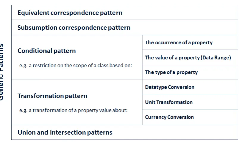
[image:26.595.110.512.305.544.2]There are various kinds of patterns3 for classification in the ontology engineering field [Blomqvist 2005]. This section specifically reviews the work in Francois Scharffe and Dieter Fensel’s research [Scharffe 2008], which is a renowned research study in the ontology mapping field. The research study is well-known because the researchers surveyed patterns in ontology mapping relationships and published detailed correspondence patterns that are at the top level of abstraction of the ontology alignment4 representation stack [Scharffe 2008]. Table 2-1 shows the categorization of generic correspondence patterns from their research.
Table 2-1 Ontology mapping categorization by F. Scharffe and D. Fensel
Scharffe’s research of correspondence patterns defines mapping relationships in six generic patterns: (1) Equivalent correspondence pattern: the pattern usually used to solve a terminological mismatch; (2) Subsumption correspondence pattern: the
3
In software engineering, patterns are an accepted way to facilitate and support reuse [Blomqvist 2005].
4
12
pattern typically solves a granularity mismatch; (3) Conditional pattern: the pattern requires a restriction to narrow down the scope of an entity in an ontology to match the scope of an entity in the another ontology, e.g. a restriction on the scope of a class based on 1. the occurrence, 2. the value or 3. the type of an attribute; (4) Transformation pattern: the pattern requires a transformation of a property value to fit the corresponding property in the another ontology, e.g. the transformation about 1. data type conversion, 2. unit transformation and 3. currency conversion; and (5) Union and (6) Intersection patterns: these patterns are used to relate entities modelled at a different granularity.
In the following sections, the categorization of correspondence patterns will be used in the discussion of the abstract and concrete syntaxes for semantic mapping to illustrate their relative capabilities and limitations. In this thesis, instead of using the terminology ‘correspondence pattern’, this research uses the term ‘mapping type’ in order to express the category of mapping relationships more plainly.
2.2 Ontology mapping application
There have been investigations into ontology mapping applications that support the mapping process [Shvaiko 2005][Granitzer 2010], and many of the existing mapping applications: PROMPT [Noy 2003], CoGZ [Falconer 2007b], COMA++ [Aumuller 2005], OLA [Euzenat 2004a] and Schema Mapper [Raghavan 2005] are designed to support a matching activity of mapping process.
13
Figure 2-1 Screenshot of PROMPT by N. F. Noy and M. A. Musen
14
Figure 2-2 Screenshot of CoGZ by S. Falconer and M. A. Storey
This research reviewed two ontology mapping application samples according to their limitations about the mapping type supports and automated process to facilitate the semantic data integration task. There are other ontology mapping applications [Granitzer 2010]. Nevertheless, most applications are designed to only support an one-to-one equivalent/subsumption mapping [Shvaiko 2005][Thomas 2009], and the main focus of the current mapping applications is in assisting to discover the possible mappings between two ontologies [Grau 2013][Shvaiko 2013]. A matching activity is one of important mapping process. However, more automated process - to generate a concrete mapping syntax from abstract and to perform the actual integration of semantic data - is required to facilitate the semantic data integration task for non-ontology background users, and the mapping applications need to support more precise mappings such as a mapping that requires constraint on the data value of property and a mapping that transforms the data value of property to be more usable in a practical integration situation.
2.3 Abstract syntaxes for semantic mapping
15
describe semantic mapping relationships at an abstract level. These abstract syntaxes may require less ontological knowledge than concrete syntaxes, because abstract syntaxes use a more convenient and natural representation of mapping rules. This section reviews these abstract syntaxes in order to determine their characteristics and examine their capability of describing ontology mapping relationships.
2.3.1 Alignment Format
Alignment Format [Euzenat 2010] was developed to express a set of pairs of mapping elements from source and target ontologies in an XML format. This syntax describes the general mapping information with the properties: xml, level, type, onto1, onto2, and map. The detail mapping information between two entities is described by the properties: entity1, entity2, measure, and relation. This Alignment Format syntax is well known for its practical use in the Ontology Alignment Evaluation Initiative (OAEI) Campaign [OAEI 2012] as it is the formal mapping document format for this initiative. Fig. 2-3 shows an example of an equivalent mapping type using Alignment Format syntax, i.e. ‘MEDTESTFEMTO’ is equivalent to ‘MediumHandoverFemto’. The measure property refers to the accuracy of the mapping relationship, e.g. in the figure, measure value 1.0 means the equivalent relationship is very accurate. As shown in the figure, this syntax uses simple vocabularies. However, it focuses primarily on one to one mappings and does not offer much expressiveness. For example, this syntax cannot be used to describe the conditional mapping type and the transformation mapping type.
<map> <Cell>
<entity1 rdf:resource=“http://www.owl-ontologies.com/femto10.owl#MEDTESTFEMTO”/> <entity2
rdf:resource=“http://www.owl-ontologies.com/FemtoOntology.owl#MediumHandoverFemto”/> <relation>=</relation>
<measure rdf:datatype=“xsd:float”>1.0</measure> </Cell>
</map>
16
2.3.2 EDOAL
Expressive and Declarative Ontology Alignment Language (EDOAL) [Euzenat 2011] extends the Alignment Format by extending the expressiveness. Particularly, it is designed for the representation of complex mappings. This syntax enables more precise relationships between entities, more than equivalence or subsumption relationships, by using the operators: and, or, not, compose, inverse, transitive, reflexive, and symmetric. This enables more mapping expressiveness than the Alignment Format syntax. One example of this expressiveness is the conditional mapping type. Fig. 2-4 shows an example of a conditional mapping type that has a constraint on the value of a datatype property (data range) using EDOAL syntax, i.e. ‘Femto’ is equivalent to ‘MediumHandoverFemto’ with the data range constraint (40 < ‘MTS_Handover_Failure_Rate’ < 60 and 40 < ‘UMTS_Handover_Failure_Rate’ < 60). <map> <cell> <entity1> <edoal:Class> <edoal:and rdf:parseType=“Collection”> <edoal:Class rdf:about=“&ont1;Femto”/> <edoal:AttributeValueRestriction> <edoal:onAttribute>
<edoal:Property rdf:about=“&ont1; MTS_Handover_Failure_Rate”/> </edoal:onAttribute>
<edoal:comparator rdf:resource=“&xsd;lower-than”/> <edoal:value>60</edoal:value>
</edoal:AttributeValueRestriction> <edoal:AttributeValueRestriction> <edoal:onAttribute>
<edoal:Property rdf:about=“&ont1; MTS_Handover_Failure_Rate”/> </edoal:onAttribute>
<edoal:comparator rdf:resource=“&xsd;greater-than”/> <edoal:value>40</edoal:value>
</edoal:AttributeValueRestriction> <edoal:AttributeValueRestriction> <edoal:onAttribute>
<edoal:Property rdf:about=“&ont1; UMTS_Handover_Failure_Rate”/> </edoal:onAttribute>
<edoal:comparator rdf:resource=“&xsd;lower-than”/> <edoal:value>60</edoal:value>
</edoal:AttributeValueRestriction> <edoal:AttributeValueRestriction> <edoal:onAttribute>
<edoal:Property rdf:about=“&ont1; UMTS_Handover_Failure_Rate”/> </edoal:onAttribute>
17 </edoal:AttributeValueRestriction> </edoal:and> </edoal:Class> </entity1> <entity2>
<edoal:Class rdf:about=“&ont2;MediumHandoverFemto”/> </entity2>
<relation>Equivalence</relation>
<measure rdf:datatype=“&xsd;float”>1.0</measure> </cell>
</map>
Figure 2-4 EDOAL syntax example for conditional mapping type
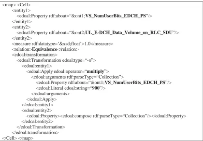
Fig. 2-5 shows an example of a transformation mapping type that transforms the data value of a property (unit transformation) using EDOAL syntax, i.e. the value of ‘VS_NumUserBits_EDCH_PS’ is equivalent to the value of ‘UL_E-DCH_Data_Volume_on_RLC_SDU’ with the unit transformation (‘VS_NumUserBits_EDCH_PS’ * 900). However, this syntax supports a limited transformation mapping type, which transforms only the value of datatype properties expressed in the entity clause. It is not possible to express the transformation mapping that requires the combination of multiple datatype properties which belong to a certain class instance and are not expressed as a source or target entity.
<map> <Cell> <entity1>
<edoal:Property rdf:about=“&ont1;VS_NumUserBits_EDCH_PS”/> </entity1>
<entity2>
<edoal:Property rdf:about=“&ont2;UL_E-DCH_Data_Volume_on_RLC_SDU”/> </entity2>
<measure rdf:datatype=‘&xsd;float‘>1.0</measure> <relation>Equivalence</relation>
<edoal:transformation>
<edoal:Transformation edoal:type=“-o”> <edoal:entity1>
<edoal:Apply edoal:operator=“multiply”> <edoal:arguments rdf:parseType=“Collection”>
<edoal:Property rdf:about=“&ont1;VS_NumUserBits_EDCH_PS”/> <edoal:Literal edoal:string=“900”/>
[image:32.595.95.516.431.723.2]</edoal:arguments> </edoal:Apply> </edoal:entity1> <edoal:entity2> <edoal:Property><edoal:compose rdf:parseType=“Collection”/></edoal:Property> </edoal:entity2> </edoal:Transformation> </edoal:transformation> </Cell> </map>
18
2.3.3 C-OWL
Contextualized OWL (C-OWL) [Bouquet 2003] has been developed to map contextualized ontologies (local models encoding the view of a group of people on a domain) to a shared ontology (a shared model encoding a common view of different parties on some domains). C-OWL keeps mappings explicitly and extends the OWL syntax. It uses bridge rules to express the mapping. These rules have five different attributes, i.e. equiv, onto, into, compat, and incompat. Each of these attributes describes a particular relationship, respectively: equivalent, less specific (subsumes), more specific (subsumedBy), compatible, and disjoint. Fig. 2-6 shows an example of an equivalent mapping type using C-OWL syntax, i.e. ‘User’ is equivalent to ‘Account’.
<cowl:bridgRule cowl:br-type=“equiv”> <cowl:sourceConcept
rdf:resource=“http://www.semanticweb.org/ontologies/SampleTelcoOnt2.owl#User”/> <cowl:targedConcept
rdf:resource=“http://www.semanticweb.org/ontologies/SampleTelcoOnt1.owl#Account”/> </cowl:bridgRule>
Figure 2-6 C-OWL syntax example for equivalent mapping type
Fig. 2-7 shows an example of a subsumption mapping type using C-OWL syntax, i.e. ‘WiFi’ is subsumed by ‘Packet_Network’. As shown in the figures, this syntax represents the mappings in a simple and explicit way between source and target ontologies. However, because of limited vocabularies for mapping expressions, this syntax cannot express the conditional mapping type and the transformation mapping type.
<cowl:bridgRule cowl:br-type=“into”> <cowl:sourceConcept
rdf:resource=“http://www.semanticweb.org/ontologies/SampleTelcoOnt2.owl#WiFi”/> <cowl:targedConcept
rdf:resource=“http://www.semanticweb.org/ontologies/SampleTelcoOnt1.owl#Packet_Network”/> </cowl:bridgRule>
Figure 2-7 C-OWL syntax example for subsumption mapping type
2.3.4 SSE
19
syntax is capable of describing mappings that may require expression of data range constraints or unit transformations. Fig. 2-8 shows an example of a conditional mapping type that has a constraint on the value of a datatype property (data range) using SSE syntax, i.e. an instance that satisfies the data range condition (40 < ‘MTS_Handover_Failure_Rate’ < 60 and 40 < ‘UMTS_Handover_Failure_Rate’ < 60) is the instance of ‘MediumHandoverFemto’.
(prefix ( (ftoc: <http://sample.org/ontology/test/femto>) ) (distinct
(project ( [triple ?femto a ftoc:MediumHandoverFemto] ) (leftjoin
(BGP
[triple ?femto ftoc:MTS_Handover_Failure_Rate ?v1] [triple ?femto ftoc:UMTS_Handover_Failure_Rate ?v2] )
( FILTER (<= 40 ?v1) ) ( FILTER (>= 60 ?v1) ) ( FILTER (<= 40 ?v2) ) ( FILTER (>= 60 ?v2) ) ))))
Figure 2-8 SSE syntax example for conditional mapping type
Fig. 2-9 shows an example of a transformation mapping type that transforms the data value of a property (unit transformation) using SSE syntax, i.e. the value of ‘Handover_Failure_Gauge’ is the result of unit transformation operation (‘MTS_Handover_Failure_Rate’ + ‘UMTS_Handover_Failure_Rate’ / 100).
(prefix ( (ftoc: <http://sample.org/ontology/test/femto>) ) (distinct
(project ( [triple ?femto ftoc:Handover_Failure_Gauge ?value] ) (leftjoin
(BGP
[triple ?femto ftoc:MTS_Handover_Failure_Rate ?v1] [triple ?femto ftoc:UMTS_Handover_Failure_Rate ?v2] )
( BIND (?value ( (?v1 + ?v2) / 100) ) ))))
Figure 2-9 SSE syntax example for transformation mapping type
2.3.5 SQWRL
20
in the Protégé tool [Protégé Project] to facilitate the creation and modification of the SWRL syntax. Its query structure is based on SWRL and it supports SWRL expressivity with more abstracted expressions. Fig. 2-10 shows an example of a conditional mapping type that has a constraint on the value of a datatype property (data range) using SQWRL syntax, i.e. ‘Femto’ is equivalent to ‘MediumHandoverFemto’ with the data range constraint (40 <= ‘MTS_Handover_Failure_Rate’ <= 60 and 40 <= ‘UMTS_Handover_Failure_Rate’ <= 60).
Femto(?x), MTS_Handover_Failure_Rate(?x, ?v2), UMTS_Handover_Failure_Rate(?x, ?v1), greaterThanOrEqual(?v1, “40”^^long), greaterThanOrEqual(?v2, “40”^^long),
lessThanOrEqual(?v1, “60”^^long), lessThanOrEqual(?v2, “60”^^long) → MediumHandoverFemto(?x)
Figure 2-10 SQWRL syntax example for conditional mapping type
Fig. 2-11 shows an example of a transformation mapping type that transforms the data value of a property (unit transformation) using SQWRL syntax, i.e. the value of ‘BSR_cluster_to_MTS_underlay_Intra_Frequency_Hard_Handover_Failure_Rate’ is the result of unit transformation operation ((1 - (‘VS_HHO_SuccBsrUmtsIntraFreq’ / ‘VS_HHO_AttBsrUmtsIntraFreq’) * 100)).
Femto(?x), hasNPMData(?x, ?pm1), VS_HHO_AttBsrUmtsIntraFreq(?pm1, ?v0),
VS_HHO_SuccBsrUmtsIntraFreq(?pm1, ?v1), divide(?div1, ?v1, ?v0), subtract(?sub1, “1”^^long, ?div1), multiply(?ans, “100”^^long, ?sub1)
→ BSR_cluster_to_MTS_underlay_Intra_Frequency_Hard_Handover_Failure_Rate(?x, ?ans)
Figure 2-11 SQWRL syntax example for transformation mapping type
2.3.6 RIF
21 Document (
Prefix ( ftoc <http://sample.org/ontology/test/femto#> ) Group (
Forall ?Femto ?MediumHandoverFemto ?MTS_Handover_Failure_Rate ?UMTS_Handover_Failure_Rate (
ftoc:equal( ?Femto ?MediumHandoverFemto ) :- And (
ftoc:Femto( ?femto )
ftoc:MTS_Handover_Failure_Rate( ?femto ?v1 ) ftoc:UMTS_Handover_Failure_Rate( ?femto ?v2 ) External( pred:numeric-greater-than(?v1 40) ) External( pred:numeric-less-than(?v1 60) ) External( pred:numeric-greater-than(?v2 40) ) External( pred:numeric-less-than(?v 60) ) ))))
Figure 2-12 RIF syntax example for conditional mapping type
Fig. 2-13 shows an example of a transformation mapping type that transforms the data value of a property (unit transformation) using RIF syntax, i.e. the value of ‘Handover_Failure_Gauge’ is the result of unit transformation operation (‘MTS_Handover_Failure_Rate’ + ‘UMTS_Handover_Failure_Rate’ / 100).
Document (
Prefix ( ftoc <http://sample.org/ontology/test/femto#> ) Group (
Forall ?Femto ?Handover_Failure_Gauge ?MTS_Handover_Failure_Rate ?UMTS_Handover_Failure_Rate (
ftoc:Handover_Failure_Gauge( ?Femto ?value ) :- And (
ftoc:Femto( ?femto )
ftoc:MTS_Handover_Failure_Rate( ?femto ?v1 ) ftoc:UMTS_Handover_Failure_Rate( ?femto ?v2 ) ?v3 = External( func:add(?v1 ?v2) )
?value = External( func:devide(?v3 100) ) ))))
Figure 2-13 RIF syntax example for transformation mapping type
2.3.7 UML/ODM
22
2010] has standardized ontology definition metamodel specification, called the ODM [ODM 1.0]. This standard describes how ontological terms can be mapped to UML notations. For example, the UML generalization with <<rdfsSubClassOf>> stereotype is used to represent “subClassOf” vocabulary in RDFS syntax [RDF Schema]. Fig. 2-14 shows an example of UML notations that represent an ontology class and property. In this figure, the UML notations represent a ‘Network Device’ ontology class that has ‘hasPort’ ontology property whose value is an instance of ‘Interface’ ontology class.
Figure 2-14 UML/ODM example for ontology class and property
Fig. 2-15 shows an example of UML notations that represent an ontology datatype property. In this figure, the UML notations represent a ‘Byte’ ontology datatype property that has the value type ‘Integer’.
Figure 2-15 UML/ODM example for ontology datatype property
23
Figure 2-16 UML/ODM example for equivalent mapping type
There are limitations on describing mapping relationships using ODM. Firstly this ODM specification only supports OWL version 1 and shares the limitations of OWL version 1, i.e. the lack of the ability to describe the data range constraints (this expression is supported from OWL version 2 [Horrocks 2010]), and secondly this specification does not support arithmetic expressions.
2.3.8 UML/OCL
Object Constraint Language (OCL) [OCL 2.0] is a formal language that enables UML constraints to be modelled in an unambiguous means. It avoids contradictions in the intended UML semantics by describing rules between UML notations. For example, OCL can describe the mapping that constrains property values using the comparison or arithmetic operation between UML notations. This language is expressed in UML constraint5 notation. Fig. 2-17 shows an example of a conditional mapping type that has a constraint on the value of a datatype property (data range) using OCL syntax, i.e. an instance in ‘Femto’ class that satisfies the data range
5
24
condition (50 < ‘handoverFailureRate’ < 90) is the instance of ‘MediumHandoverFemto’.
Figure 2-17 UML/OCL example for conditional mapping type
Fig. 2-18 shows an example of a transformation mapping type that transforms the data value of a property (unit transformation) using OCL syntax, i.e. the value of ‘byte’ is the result of unit transformation operation (‘bit’ * 8).
Figure 2-18 UML/OCL example for transformation mapping type
2.4 Concrete syntaxes for semantic mapping
25
three different approaches of integration that are popular: Axiomatic, Rule and Query [Keeney 2011].
2.4.1 Using OWL for semantic mapping
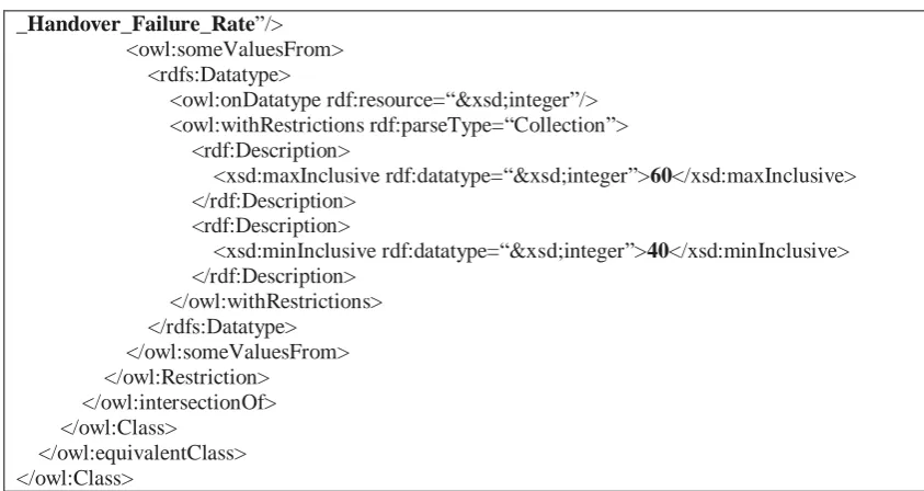
Web Ontology Language (OWL) [Bechhofer 2004] is a semantic markup language for publishing and sharing ontologies on the World Wide Web. This language has XML elements such as equivalentClass and equivalentProperty that can be used to describe mappings. If the application is ontologically based, this syntax is generally considered first to use as a concrete syntax to perform the integration task. However, the syntax has some limitations. First, mappings can be more manifest and easier to modify in a separate document. Using OWL for the mappings mixes the definitions of the concepts and mapping information [Keeney 2011]. Second, this syntax does not support data value transformation (arithmetic operations) that might be required for mapping. Fig. 2-19 shows an example of a conditional mapping type that has a constraint on the value of a datatype property (data range) using OWL syntax. In this example, ‘Femto’ class with the property ‘MTS_Handover_Failure_Rate’ value between 40 and 60, and the property ‘UMTS_Handover_Failure_Rate’ value between 40 and 60 is equivalent to ‘MediumHandoverFemto’ class.
<owl:Class rdf:about=“http://www.owl-ontologies.com/femto.owl#MediumHandoverFemto”> <owl:equivalentClass>
<owl:Class>
<owl:intersectionOf rdf:parseType=“Collection”>
<rdf:Description rdf:about=“http://www.owl-ontologies.com/femto.owl#Femto”/> <owl:Restriction>
<owl:onProperty rdf:resource=“http://www.owl-ontologies.com/femto.owl#MTS_Handover_Failure_Rate”/> <owl:someValuesFrom>
<rdfs:Datatype>
<owl:onDatatype rdf:resource=“&xsd;integer”/> <owl:withRestrictions rdf:parseType=“Collection”> <rdf:Description>
<xsd:maxInclusive rdf:datatype=“&xsd;integer”>60</xsd:maxInclusive> </rdf:Description>
<rdf:Description>
<xsd:minInclusive rdf:datatype=“&xsd;integer”>40</xsd:minInclusive> </rdf:Description> </owl:withRestrictions> </rdfs:Datatype> </owl:someValuesFrom> </owl:Restriction> <owl:Restriction>
26 _Handover_Failure_Rate”/> <owl:someValuesFrom> <rdfs:Datatype> <owl:onDatatype rdf:resource=“&xsd;integer”/> <owl:withRestrictions rdf:parseType=“Collection”> <rdf:Description>
<xsd:maxInclusive rdf:datatype=“&xsd;integer”>60</xsd:maxInclusive> </rdf:Description>
<rdf:Description>
[image:41.595.92.514.69.293.2]<xsd:minInclusive rdf:datatype=“&xsd;integer”>40</xsd:minInclusive> </rdf:Description> </owl:withRestrictions> </rdfs:Datatype> </owl:someValuesFrom> </owl:Restriction> </owl:intersectionOf> </owl:Class> </owl:equivalentClass> </owl:Class>
Figure 2-19 OWL syntax example for conditional mapping type
2.4.2 SWRL
Semantic Web Rule Language (SWRL) [Horrocks 2004] is a rule language used to express the rules in an ontology in addition to concept definitions. This syntax is based on a combination of OWL and RuleML [Boley 2011], which is a sublanguage of the Rule Markup Language. The syntax includes a high-level abstract syntax for Horn-like rules [Horn 1951] and uses the following vocabularies: XSD, OWLX, RuleML, SWRLX, and SWRLB. These vocabularies offer good expressiveness to describe mappings that may require expressing data range constraints or data value transformations (arithmetic operation). However, this syntax is difficult to generate for its rigidity that often requires domain experts to have intensive training on writing rules. Fig. 2-20 shows an example of a conditional mapping type that has a constraint on the value of a datatype property (data range) using SWRL syntax. In this example, ‘Femto’ class instances that have the property ‘UMTS_Handover_Failure_Rate’ value greater than or equal to 40 and less than or equal to 60, and the property ‘MTS_Handover_Failure_Rate’ value greater than or equal to 40 and less than or equal to 60 are the instances of ‘MediumHandoverFemto’ class.
<swrl:Imp> <swrl:body>
<swrl:AtomList><rdf:first> <swrl:ClassAtom>
27 <swrl:argument1 rdf:resource=“#x”/>
</swrl:ClassAtom></rdf:first><rdf:rest><swrl:AtomList><rdf:first> <swrl:DatavaluedPropertyAtom>
<swrl:propertyPredicate rdf:resource=“#UMTS_Handover_Failure_Rate”/> <swrl:argument1 rdf:resource=“#x”/>
<swrl:argument2 rdf:resource=“#v1”/>
</swrl:DatavaluedPropertyAtom></rdf:first><rdf:rest><swrl:AtomList><rdf:first> <swrl:DatavaluedPropertyAtom>
<swrl:propertyPredicate rdf:resource=“#MTS_Handover_Failure_Rate”/> <swrl:argument1 rdf:resource=“#x”/>
<swrl:argument2 rdf:resource=“#v2”/>
</swrl:DatavaluedPropertyAtom></rdf:first><rdf:rest><swrl:AtomList><rdf:first> <swrl:BuiltinAtom>
<swrl:builtin rdf:resource=“http://www.w3.org/2003/11/swrlb#greaterThanOrEqual”/> <swrl:arguments><rdf:List><rdf:first rdf:resource=“#v1”/><rdf:rest><rdf:List>
<rdf:first rdf:datatype=“http://www.w3.org/2001/XMLSchema#long”>40</rdf:first> <rdf:rest rdf:resource=“http://www.w3.org/1999/02/22-rdf-syntax-ns#nil”/>
</rdf:List></rdf:rest></rdf:List> </swrl:arguments>
</swrl:BuiltinAtom></rdf:first><rdf:rest><swrl:AtomList><rdf:first> <swrl:BuiltinAtom>
<swrl:builtin rdf:resource=“http://www.w3.org/2003/11/swrlb#lessThanOrEqual”/> <swrl:arguments>
<rdf:List><rdf:rest><rdf:List>
<rdf:first rdf:datatype=“http://www.w3.org/2001/XMLSchema#long”>60</rdf:first> <rdf:rest rdf:resource=“http://www.w3.org/1999/02/22-rdf-syntax-ns#nil”/>
</rdf:List></rdf:rest><rdf:first rdf:resource=“#v1”/></rdf:List></swrl:arguments> </swrl:BuiltinAtom></rdf:first><rdf:rest><swrl:AtomList><rdf:first>
<swrl:BuiltinAtom>
<swrl:builtin rdf:resource=“http://www.w3.org/2003/11/swrlb#greaterThanOrEqual”/> <swrl:arguments><rdf:List><rdf:first rdf:resource=“#v2”/><rdf:rest><rdf:List>
<rdf:first rdf:datatype=“http://www.w3.org/2001/XMLSchema#long”>40</rdf:first> <rdf:rest rdf:resource=“http://www.w3.org/1999/02/22-rdf-syntax-ns#nil”/>
</rdf:List></rdf:rest></rdf:List> </swrl:arguments>
</swrl:BuiltinAtom></rdf:first><rdf:rest><swrl:AtomList><rdf:rest
rdf:resource=“http://www.w3.org/1999/02/22-rdf-syntax-ns#nil”/><rdf:first><swrl:BuiltinAtom> <swrl:builtin rdf:resource=“http://www.w3.org/2003/11/swrlb#lessThanOrEqual”/>
<swrl:arguments><rdf:List><rdf:first rdf:resource=“#v2”/><rdf:rest><rdf:List> <rdf:first rdf:datatype=“http://www.w3.org/2001/XMLSchema#long”>60</rdf:first> <rdf:rest rdf:resource=“http://www.w3.org/1999/02/22-rdf-syntax-ns#nil”/> </rdf:List></rdf:rest></rdf:List> </swrl:arguments> </swrl:BuiltinAtom> </rdf:first></swrl:AtomList></rdf:rest></swrl:AtomList></rdf:rest></swrl:AtomList></rdf:rest></sw rl:AtomList></rdf:rest></swrl:AtomList></rdf:rest></swrl:AtomList></rdf:rest></swrl:AtomList> </swrl:body> <swrl:head> <swrl:AtomList><rdf:first> <swrl:ClassAtom>
<swrl:classPredicate rdf:resource=“#MediumHandoverFemto”/> <swrl:argument1 rdf:resource=“#x”/>
</swrl:ClassAtom></rdf:first><rdf:rest rdf:resource=“http://www.w3.org/1999/02/22-rdf-syntax-ns#nil”/></swrl:AtomList>
</swrl:head> </swrl:Imp>
28
Fig. 2-21 shows an example of a transformation mapping type that transforms the data value of a property (unit transformation) using SWRL syntax. In this example, the property ‘MTS_Handover_Failure_Rate’ value of the instance in ‘Femto’ class will be assigned by the transformation of values of the ‘hasNPMData’ instance properties ‘VS_HHO_AttBsrUmtsIntraFreq’ and ‘VS_HHO_SuccBsrUmtsIntraFreq’ by the arithmetic operation ((1 subtract by (‘VS_HHO_SuccBsrUmtsIntraFreq’ value divide by ‘VS_HHO_AttBsrUmtsIntraFreq’ value)) multiply by 100).
<swrl:Imp> <swrl:body>
<swrl:AtomList><rdf:first><swrl:ClassAtom><swrl:classPredicate rdf:resource=“http://www.owl-ontologies.com/Ontology1304066878.owl#Femto”/><swrl:argument1 rdf:resource=“http://www.owl-ontologies.com/Ontology1304066878.owl#x”/></swrl:ClassAtom></rdf:first><rdf:rest><swrl:AtomL ist><rdf:rest><swrl:AtomList><rdf:first><swrl:DatavaluedPropertyAtom><swrl:propertyPredicate
rdf:resource=“http://www.owl-ontologies.com/Ontology1304066878.owl#VS_HHO_AttBsrUmtsIntraFreq”/><swrl:argument1 rdf:resource=“http://www.owl-ontologies.com/Ontology1304066878.owl#pm1”/><swrl:argument2
rdf:resource=“http://www.owl-ontologies.com/Ontology1304066878.owl#v0”/></swrl:DatavaluedPropertyAtom></rdf:first><rdf:res t><swrl:AtomList><rdf:rest><swrl:AtomList><rdf:first>
<swrl:BuiltinAtom><swrl:builtin rdf:resource=“&swrlb;divide”/>
<swrl:arguments rdf:parseType=“Collection”><rdf:Description ontologies.com/Ontology1304066878.owl#div1”/><rdf:Description ontologies.com/Ontology1304066878.owl#v1”/><rdf:Description rdf:about=“http://www.owl-ontologies.com/Ontology1304066878.owl#v0”/></swrl:arguments></swrl:BuiltinAtom></rdf:first>< rdf:rest><swrl:AtomList><rdf:first>
<swrl:BuiltinAtom><swrl:builtin rdf:resource=“&swrlb;multiply”/>
<swrl:arguments><rdf:Description><rdf:type rdf:resource=“&rdf;List”/><rdf:first
rdf:resource=“http://www.owl-ontologies.com/Ontology1304066878.owl#ans”/><rdf:rest><rdf:Description><rdf:type rdf:resource=“&rdf;List”/><rdf:first rdf:datatype=“&xsd;long”>100</rdf:first><rdf:rest rdf:parseType=“Collection”><rdf:Description
rdf:about=“http://www.owl-ontologies.com/Ontology1304066878.owl#sub1”/></rdf:rest></rdf:Description></rdf:rest></rdf:Desc ription></swrl:arguments></swrl:BuiltinAtom></rdf:first><rdf:rest><swrl:AtomList><rdf:rest rdf:resource=“&rdf;nil”/><rdf:first>
<swrl:BuiltinAtom><swrl:builtin rdf:resource=“&swrlb;subtract”/>
<swrl:arguments><rdf:Description><rdf:type rdf:resource=“&rdf;List”/><rdf:first
rdf:resource=“http://www.owl-ontologies.com/Ontology1304066878.owl#sub1”/><rdf:rest><rdf:Description><rdf:type rdf:resource=“&rdf;List”/><rdf:first rdf:datatype=“&xsd;long”>1</rdf:first><rdf:rest rdf:parseType=“Collection”><rdf:Description rdf:about=“http://www.owl-ontologies.com/Ontology1304066878.owl#div1”/></rdf:rest></rdf:Description></rdf:rest></rdf:Desc ription></swrl:arguments></swrl:BuiltinAtom></rdf:first></swrl:AtomList> </rdf:rest></swrl:AtomList> </rdf:rest></swrl:AtomList> </rdf:rest><rdf:first><swrl:DatavaluedPropertyAtom><swrl:propertyPredicate
rdf:resource=“http://www.owl-ontologies.com/Ontology1304066878.owl#VS_HHO_SuccBsrUmtsIntraFreq”/><swrl:argument1 rdf:resource=“http://www.owl-ontologies.com/Ontology1304066878.owl#pm1”/><swrl:argument2
29 </rdf:rest></swrl:AtomList>
</rdf:rest><rdf:first><swrl:IndividualPropertyAtom><swrl:propertyPredicate
rdf:resource=“http://www.owl-ontologies.com/Ontology1304066878.owl#hasNPMData”/><swrl:argument2
rdf:resource=“http://www.owl-ontologies.com/Ontology1304066878.owl#pm1”/><swrl:argument1 rdf:resource=“http://www.owl-ontologies.com/Ontology1304066878.owl#x”/></swrl:IndividualPropertyAtom></rdf:first></swrl:At omList> </rdf:rest></swrl:AtomList> </swrl:body> <swrl:head> <swrl:AtomList><rdf:rest rdf:resource=“&rdf;nil”/><rdf:first><swrl:DatavaluedPropertyAtom><swrl:propertyPredicate
rdf:resource=“http://www.owl-ontologies.com/Ontology1304066878.owl#MTS_Handover_Failure_Rate”/><swrl:argument2 rdf:resource=“http://www.owl-ontologies.com/Ontology1304066878.owl#ans”/><swrl:argument1 rdf:resource=“http://www.owl-ontologies.com/Ontology1304066878.owl#x”/></swrl:DatavaluedPropertyAtom></rdf:first></swrl:A tomList> </swrl:head> </swrl:Imp>
Figure 2-21 SWRL syntax example for transformation mapping type
2.4.3 SPARQL
30 CONSTRUCT { $femto a :MediumHandoverFemto . } WHERE {
$femto :MTS_Handover_Failure_Rate $v2 ; :UMTS_Handover_Failure_Rate $v1 .
FILTER ( 40 <= $v1 && $v1 <= 60 && 40 <= $v2 && $v2 <= 60 ) }
Figure 2-22 SPARQL syntax example for conditional mapping type
Fig. 2-23 shows an example of a transformation mapping type that transforms the data value of a property (unit transformation) using SPARQL syntax. In this example, the ‘Femto’ instance will have the property ‘MTS_Handover_Failure_Rate’ value that is the transformation result of the values of ‘hasNPMData’ instance properties ‘VS_HHO_AttBsrUmtsIntraFreq’ and ‘VS_HHO_SuccBsrUmtsIntraFreq’ by the arithmetic operation ((1 - (‘VS_HHO_SuccBsrUmtsIntraFreq’ value / ‘VS_HHO_AttBsrUmtsIntraFreq’ value)) * 100).
CONSTRUCT { $femto :MTS_Handover_Failure_Rate $kpi . } WHERE {
$femto a :Femto ; :hasNPMData $npm .
$npm :VS_HHO_AttBsrUmtsIntraFreq $v0 . $npm :VS_HHO_SuccBsrUmtsIntraFreq $v1 . BIND ( (1 - ($v1 / $v0)) * 100 as $kpi )
}
Figure 2-23 SPARQL syntax example for transformation mapping type
2.5 Summary Tables
31
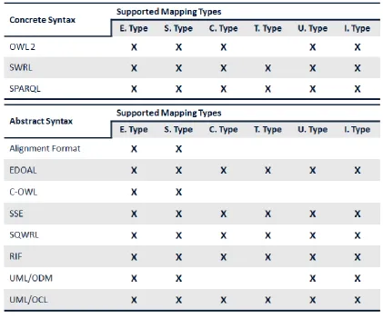
Table 2-2 Summary table of the supported mapping types for concrete and abstract mapping
32
Table 2-3 Summary table of the usability and type of expression for concrete and abstract
mapping syntaxes
33
modification of the mapped entities are not quite obvious because the result of each consequent of the rules is not explicit in this expression.
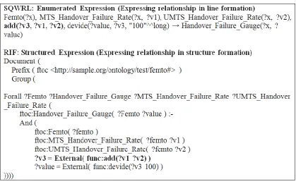
The other category is structured type expression. This means mapping relationships are expressed in structured formation such as RIF. They are relatively more difficult to generate in the first place by human perspective than enumerated expression because this expression separates each rule or mapped entity with order. However, the discovery of the mapping relationships and the modification of the mapped entities are quite obvious because the result of each consequent of the rules is explicitly grouped in a structured form.
34
Figure 2-24 Enumerated and structured type expression
35
assistance. UML uses a graphic-based expression that is traditionally proven as a better approach than a text-based approach. In addition, UML [UML 2011] is widely used in many areas to model data structure, application structure, application behaviour, and business processes in a standardized and easy-to-understand manner [Kogut 2002]. It is the dominant language becoming the de facto standard for describing system applications, and system engineers are familiar with UML notations [Gasevic 2004]. It was thus decided in our research to use UML as the means to allow a system engineer to express mappings in an abstract manner.
36
3
MOUSE Approach
This chapter describes three core mapping types derived from the industry use case, and the development of a UML-based abstract mapping syntax that can represent defined core mapping types.
3.1 The Core Mapping Types
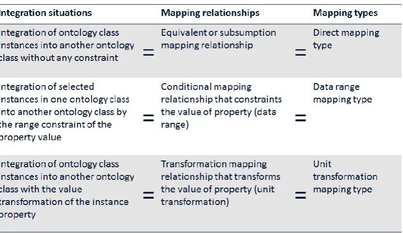
This section describes three core mapping types: (1) Direct Mapping Type, (2) Data Range Mapping Type and (3) Unit Transformation Mapping Type that need to be captured correctly for the abstract syntax to be usable in a practical integration situation.
3.1.1 Industry Use Case
SDA6 (Semantic Data Access) is a research program initiated by Alcatel-Lucent Bell Labs Ireland [Boran 2011b]. This program constitutes several modules of industry and PhD research that aim to create a semantic data access plane within the telecommunications network. This access plane will facilitate the modelling of, integration of, and reasoning of heterogeneous data sources and will support third-party enterprises accessing data in a unified approach for lifting rough refined raw semantic data to rich semantic data. Because parts of this study fit within this large industrial research program inside Alcatel-Lucent Bell Labs Ireland, which provided the semantic mapping representation to support the SDA, there was collaboration with Bell Labs Ireland throughout this research; mainly supplying their industry use case.
This industry use case was the result of the research [Boran 2011a] conducted by Bell Labs Ireland about empirical analysis for network performance classification.
6
37
The use case is about the classification of network performance by semantic up-lift using real network ontology data collected from an Alcatel-Lucent femtocell [Small Cell] test bed. The performance management (PM) data is periodically collected and stored as an instance in raw-level ontology and then processed to generate key performance indicators (KPI) from the calculation over the PM data. The performance of the femtocell network is evaluated according to the KPIs - in total 19 rules were required to compute the set of 19 KPIs - and classified the femtocells into 15 performance-related classifications in femto-level ontology. APPENDIX A shows femto-level (femtoclassifier.owl) ontology and raw-level (femtoinstances.owl) ontology from the industry use case. In the appendix, all the ontology individuals are removed because of the large volume.
This process requires semantic mappings to integrate a femtocell instance in raw-level ontology to femto-raw-level ontology. For example, a femtocell is classified as ‘HighHandoverFemto’ in femto ontology if the generated KPI value of ‘BSR_cluster_to_MTS_underlay_Intra_Frequency_Hard_Handover_Failure_Rate’ is higher or equal to 90. The KPI values are generated by processing the PM data collected from the femtocell in the telecommunications network, i.e. ‘BSR_cluster_to_MTS_underlay_Intra_Frequency_Hard_Handover_Failure_Rate’ = (1 - (‘VS_HHO_SuccBsrUmtsIntraFreq’ value / ‘VS_HHO_AttBsrUmtsIntraFreq’ value)) * 100).
38
Table 3-1 Relationship between the semantic intergration situations and the core mapping
types