Journal of Criminal Law and Criminology
Volume 61 | Issue 3
Article 9
1971
Forensic Applications of the Scanning Electron
Microscope
E. J. Korda
H. L. MacDonell
J. P. Williams
Follow this and additional works at:
https://scholarlycommons.law.northwestern.edu/jclc
Part of the
Criminal Law Commons
,
Criminology Commons
, and the
Criminology and Criminal
Justice Commons
This Article is brought to you for free and open access by Northwestern University School of Law Scholarly Commons. It has been accepted for inclusion in Journal of Criminal Law and Criminology by an authorized editor of Northwestern University School of Law Scholarly Commons.
Recommended Citation
Tim TounNAL o7 Canun LTw, Cmncwo, or Aw Powcz Srcz
Copyright 0 1970 by Northwestern University School of I w Printe in U.S.A.Vol. 61, No. 3
FORENSIC APPLICATIONS OF THE SCANNING ELECTRON MICROSCOPE*
E. J. KORDA, H. L. MACDONELL AND
J.
P. WILLIAMSE. J. Korda is a Research Scientist, Instrumental Analysis, Coming Glass Works, Coming, New
York. He was an Associate Professor of Metallurgy at the Drexel Institute of Technology, Phila-delphia, and Director of their Electron Microscopy Laboratory.
H. L. MacDonell is a Research Chemist, Coming Glass Works and a Consulting Criminalist. Mr. MacDonell has previously served as a Forensic Scientist at the Rhode Island State Crime Laboratory and has taught police science courses at the Corning Community College. He is a fellow of the Amer-ican Academy of Forensic Sciences and a member of the Canadian Society of Forensic Sciences. His publications have appeared in a number of professional journals.
J. P. Williams, Ph.D. is Manager of the Instrumental Analysis Research at the Research
and'Devel-opment Laboratories, Coming Glass Works. He has worked in the area of chemical and instrumeatal analysis at Coming since
1950.-EnrTop-The physical sciences have long been utilized
by those concerned with law enforcement.
Chemi-cal analysis, for example, has always been an essential portion of toxicology. In 1832 Coley published the book Poisons and Asphyxia con-taining the chemical analysis procedures of that period. (1) Bertillon developed a system of anthro-pometric measurements in 1882 which permitted the classification of prisoners. (2) Though the system was useful, it was not infallible and finally yielded to the more accurate and practical system of fingerprint identification. (3, 4) Likewise, with improvements in firearms and ammunition there followed advances in firearms identification using characteristics not possible with earlier cap and ball smoothbore weapons.
During the past fifty years a few dedicated pioneers in scientific crime investigation have slowly incorporated more science into police sci-ence. As a result, a new discipline known as criminalistics has evolved which is primarily con-cemed with physical evidence and the use of sci-ence in its examination. It is both logical and un-fortunate that considerable time is often required before developments in methodology and/or instrumentation reach their ultimate utilization. Frequently, an instrument is available that may solve a particular problem, and yet its application to the problem may go unnoticed for many years. The objective of this paper is to present some of *Portions of this paper were presented by Dr. Williams during the Symposium on Forensic Chemistry, American Chemical Society, 156th National Meeting held in Atlantic City, New Jersey, Wednesday 11, September 1968. Mr. MacDonell was Chairman of the Symposium.
the possible applications of scanning electron microscopy (SEM) to the field of criminalistics and thus to suggest expanded use of this new microscope for forensic purposes.
[image:2.454.241.418.381.617.2]The SEM has evolved from the work of a num-ber of scientists over the past 30 or more years. (5) The first commercial instrument, which became available in 1965, was based primarily on the activities of a group at the University of Cam-bridge under the direction of Oatley. (6) A sche-matic drawing of the SEM is shown in Figure 1. A beam of electrons is generated by a tungsten
FIGURE 1
E. J. KORDA, H. L. MACDONELL AND J. P. WILLIAMS
COMPARISON OF
TABLE 1
OPTICAL, SCANNING, AND TRa ArsMIssIoN ELEcTRoN MIcRoscoPY
Comparison Factors Optical Microscopy Scanning Electron Microscopy Transmission ElectronMicroscopy
Magnification Range 1 to 1200X 50 to 30,000X 500 to 250, OOOX
Resolution Possible 2,000
A
150 to 200A
<5 to 50A
Relativ' Depth of Focus 1 300
Type of Obseivation Direct Direct Mainly Replica Direct
Difficult
Sample Preparation Time Minutes tolhouis Minutes Hours to Days
Other Modes' IR, UV, Luminescent & Conduc- Electron Diffraction
tive
filame it'aitd demagnified by thiee -elctromagnetic lenses to a: spot sizeof about 100
A.'
The'accelerat-ing voltage for the electrons can be varied from 1 to 20 kv. When the primary beam strikes the specimen, the energy is converted to heat, light, X-rays, ack-scattered electron reflections, and secondary ,electron emission. In the SEM emissive mode the secondary electrons are collected from each point and integrated into a total imageon a cathode ray tube (CRT) which scans visually in synchronism with the primary beam. Magnifica-tion is achieved by the relaMagnifica-tionship of the area on the specimen scanned by the primary beam and the area pictured on the CRT.The energy range of the secondary electrons is low, in the order of 6 to 50 ev, and accordingly the secondaries can be drawn in curved trajectories
by a small positive bias to a collector-detector
system consisting~,f a focusing electrode, scintil-lator, light pine, and photomultiplier. The ability to select and detect the secondary electrons in
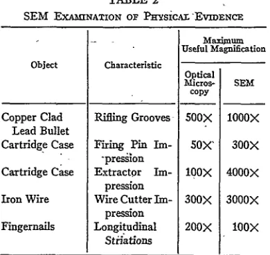
TABLE 2
SEM ExAMINATION OF PHYSiCALr "EVIDENCE
Object
Copper Clad Lead Bullet Cartridge Case
Cartridge Case
Iron Wire
Fingernails
Characteristic
Rifling Grooves
Firing Pin Im--presion Extractor
Im-pression Wire Cutter
Im-pression Longitudinal
Stiations
Maxi
Useful Ma
Optical Micros-copy 500X SOX'
bOox
300X 200X gnification SEM 1000X 300X 4000X 3000X IOoxthis manner, coupled with the fact that they are being generated at a very fine spot on'the surface of the specimen, makee the emissive mode of the SEM a superior means to examine surface topop-raphy directly with great resolution and -depth of focus. A comparison of the characteristi of opti-cal, scanning, and transmission electron micros-copy is summarized in table 1.
Specimen preparation for SEM observation is minimal. Electrical conductors, such as metals, can be studied directly. Insulators, which include organic materials, require a thin conducting coat-ing. A recommended coating is a 400
A
layer of vacuum-evaporated aluminum. Samples,. up to approximately 2 by 1 by 1 6n, are examined on a specimen stage capable of three-dimensional movement, as well as rotation and tilting, withinthe vacuum chamber of the SEM.
FORENSIC APPLICATIONS
Because of the unique capabilities of the SEM, a number of objects frequently encountered as physical evidence were examined in an attempt to define advantages of this new microscopic device. Results of the SEMA analyses are summarized in table 2 and are described in some detail in the text and micrographs which follow.
. Two .45 ACP copper clad lead projectiles were
recovered after-firing and examined for striations produced by the barrel rifling. Optical micrographs of the bullets are shown in figure 2. The micro-graphs picture a bullet mounted on a SEM sped-men holder to indicate the approximate size of sample suitable for convenient viewing. Figure 3 illustrates the detail possible for the matching of the rifling grooves of the two bullets by means of
SEM analysis. The higher magnification used for
matching of the rifling grooves in the SEM micro-graphs shown in figure 3 is approximately 300X.
[image:3.454.25.220.444.628.2]SCANNING ELECTRON, MICROSCOPE
FiGuRE 2
[image:4.454.229.421.59.294.2] [image:4.454.24.215.293.522.2]Optical micrographs of .45 ACP bullet. Top: Bullets on SEM specimen mounting. Bottom: Rifling grooves on the two bullets. Scale given as diameter of white circle in microns (,L).
FiGuRE
4
Micrographs of firing pin impression in .38 SPL cartridge cases. Top: Optical micrographs illustrating depth of focus limitations. Bottom: SEU micrographs showing superior depth of focus.
A,
4
F GURE 3
SEM micrographs of .45 ACP bullets. Top: Matched
rifling grooves of two bullets pictured in Figure 2. Bot-tom: Matched rifling grooves of same bullets.
Note that the greater magnification does not help this comparison and, if anything, it is more con-fusing. It will be demonstrated in succeeding examples that more detailed markings can be found on objects composed of relatively hard metals such as iron and brass than on objects made of soft metals such as copper and lead.
There are a number of characteristic markings which can be found on cartridge cases; these in-clude firing Din impressions and imprints made by
/ &
I
~ I
FGURE 5
SEM micrographs of firing pin impression. Top: Detail at center of pin impression in two cases. Bottom: Increased detail of pin impression in two cases.
impres-E. J. KORDA, H. L. MACDONELL AND I. P. WILLIAMS
FioGuR 6
Micrographs of extractor markings on .45 ACP cartridge cases. Top: Optical micrographs of extractor markings. Bottom: SEM micrographs of portion of extractor markings above.
: , ii
i '!!~~i
, ! i ?ii~iiiii~ ii4
l
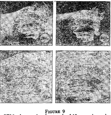
FiGuRE 9
SEM micrographs of cut ends of 18-gauge iron wire.
Top: Low magnification micrograph picturing excellent depth of focus of the two cut end surfaces. Bottom: Micrograph of the two cut surfaces illustrating the overall matching character of both specimens.
<I'
FIGTRE 7SEM micrographs of match extractor markings on two cartridge cases.
sions is clearly demonstrated in the SEM
micro-graphs at 300 X magnification. Extractor
identations on two .45 ACP cartridge cases are pictured in figures 6 and 7. Groove matching at high magnification is portrayed in the SEM micro-graphs. Similar detail could be found but with more difficulty in the case of breechblock and ejector markings. Detail was not easy to resolve in the latter two instances because of tooling grooves on the cartridge cases.
The surface of the cut ends of wire carry impres-sions of the shape and contour of the cutting edge of pliers or wire cutters. A comparison of the in-formation obtainable from optical micrographs of
two 18-gauge iron wire ends cut with the same wire cutters as contrasted to SEM micrographs is recorded in figures 8, 9, and 10. The optical micro-graphs pictured in figure 8 indicate that the light microscope has definite limitations for examining such irregular surfaces. The optical micrographs are of poor quality compared to the SEM micro-graphs in figures 9 and 10 which show excellent resolution and detail from magnifications of 100 to 3000
x.
For a number of years one of us (MacDonell) has collected fingernails to determine whether the pattern of longitudinal growth striations remains unchanged over a long period of time. A similar
[image:5.454.219.408.56.252.2]SCANNING ELECTRON MICROSCOPE
FIGURE 8
Optical micrographs of cut ends of 18-gauge iron wire. Top: Micrographs of two wire cuttings. Bottom: Micro-graphs of the cut surfaces showing maximum useful resolution of optical microscope examination.
_ : < : ;
FIGURE 10
SEM micrographs of detail in surface topography of
iron wire cuttings. Top: Detail of loop in center of micrographs pictured at bottom of Figure 9. Bottom: High magnification matching of wire cutting grooves shown at center above. The total cross section illus-trated (top to bottom) is less than Xo0th of the diam-eter of a human hair.
F GURE 11
Micrographs of fingernail sections collected one year apart. Top: Optical micrograph of Al coated specimens using reflected light. Bottom: SEM micrographs of two fingernail sections showing matching striations.
; :ii '! ii' 17 = =!Ii- - i; ;1 [7 i;;i !ii ¢,> i!iii :-!, 7 ;17i; J
[image:6.454.55.382.65.319.2] [image:6.454.232.408.375.605.2]E. J. KORDA, H. L. MACDONELL AND J. P. WILLIAMS
FIGuRE 12
Composite SEM micrograph of fingernail sections collected over time interval of five years.
investigation was reported in 1965 by Thomas and Baert (7) who used a light microscope to evaluate and match striations. While some detail is present on the top surface of fingernails, the area is usually abraded and polished to such a degree that it is of little value for identification. The underside, how-ever, contains much more detail as can be seen in figures 11 and 12. The aluminum conductive coat-ing deposited on the fcoat-ingernail specimens for SEM
examination also improved the clarity of the re-flected light optical micrographs. Both the optical and the SEM micrographs in Figure 11 present matched longitudinal striations of sections of two fingernails collected about one year apart. Figure 12 pictures a composite SEM micrograph of striations of three fingernail clippings collected at time intervals of about one and one-half years be-tween each specimen. Note that the agreement of striations is more apparent when the viewer holds the illustration so they run in a vertical rather than a horizontal configuration. This is true for any striation comparison.
CONCLUSION
The SEM can be utilized to advantage for the direct examination of surface topography on physical evidence of forensic interest. The great
depth of focus and high resolutions of the emissive mode of the SEM can reveal important micro-structural detail not readily obtained by other microscopic means. While not employed in this study, the luminescent and conductive modes of the SEM could also prove valuable in criminalistic
investigations.
ACKNOWLEDGMENTS
Mr. Raymond A. Fritz and Mrs. Georgia A. Norris provided valuable assistance in obtaining the micrographs pictured in this report.
REFERENCES
1. COLEY, HENRY, POISONS AND ASPHYXIA, publisher
unknown, New York, New York (1832).
2. BERTILLON, ALPHONSE, Identification
Anthropo-metrique, ANN. DE DEMOGRAPHIE, (1882).
3. FAULDS, HENRY, Skin Furrows of the Hand, 22
NATURE, 605, (28 Oct. 1880).
4. GALTON, FRANCIS, FINGE.RPRINTS, MacMillan, London, (1892).
5. THORNTON, P. R., SCANNING ELECTRON MICROSCOPY,
Chapman and Hall Ltd., London, (1968).
6. OATLEY, C. W., NxoN, W. C., AND PEASE, R. F. W.,
Advances in Electronics and Electron Physics, 21, 181, (1965).
7. THoms, F., AND BAERT, H., A New Means of Identification of the Human Being: The
Longi-tudinal Striation of the Nails, 5 MEDICINE,
SCIENCE AND THE LAW, 39, (1965).
[image:7.454.54.374.63.223.2]