Image Transmission over Multipath Fading Channel and
Image Denoising using Directional Weighted Median
Filter
Veeramma Yatnalli
JSS Academy of Technical Education, Bengaluru Karnataka
India
K L Sudha
Dayananda Sagar College of Engineering, Bengaluru Karnataka
India
ABSTRACT
Impulse noise is often introduced into images during transmission contaminating the images due to channel errors. Based on the noise values, impulse noise can be classified as Fixed Valued Impulsive Noise or Salt and Pepper Noise(SPN) and Random Valued Impulsive Noise(RVIN). In this paper, an inpainting algorithm is presented based on Directional Weighted Median(DWM) Filter to denoise both the noises caused due to image transmission over multipath fading channel. The algorithm diffuses median value of pixels from the exterior area into the inner area and thus preserves the edges and fine details. The random valued impulsive noise and salt and pepper noise due to wireless channel modeled are simulated using MATLAB channel objects. The detection algorithm combined with the image correction based on DWMF shows better performance in terms of Peak Signal-to-Noise Ratio(PSNR) and Mean Absolute Error(MAE).
General Terms
Image Reconstruction, Channel Fading
Keywords
Inpainting, Random Valued Impulsive Noise(RVIN), Salt and Pepper Noise, Directional Weighted Median(DWM), PSNR, MAE.
1.
INTRODUCTION
When image and video are transmitted over noisy channels, the data is either missing or incorrect due to channel transmission errors. As a result, impulse noise can appear because of a random bit error on a communication channel. The resulting two noises that corrupt the source images based on the noise value are:
Salt and Pepper impulse Noise, which means a noisy pixel has a high value due to positive impulse noise and looks like white dot or snow in the image, or has a low value due to a negative impulse noise and looks like black dot or pepper in the image.
Random Valued Impulse Noise can take any value that do not occur as extreme outliers in comparison with the surrounding pixels.
Nonlinear filters, which are based on statistical ordering of pixel values in a predefined fixed size sliding window, are effective in suppressing impulse noise in images. However, when they are applied to an image having uniformly distributed image values, undesired processing of noise-free pixels results in edge and texture blurring. The de-noising techniques based on median value works fine for restoring the images corrupted by Random Valued Impulse Noise with
low noise level but exhibits poor performance with highly corrupted images.
technique uniformly replaces the gray-level value of every pixel by the median of its neighbors in the sliding window. Consequently, some desirable details are also removed, in particular, when the window size is large. For the removal of random-valued impulse noise, a directional weighted median filters (DWM) [7] and Multi-stage Directional Median Filter (MSDWM) [8] provides a better solution. The filter [7] uses a new impulse detector, which is based on the difference between the current pixel and its neighbors aligned with four main directions. The algorithm is fast and provides good results in both edges and smooth regions. In this paper, an impulse detector, which exhibits better impulse detection capability than the others in combination with the output of the directional weighted median filter can suppress most noise while preserving more detail features and even thin lines. The method [8] can effectively restore images corrupted with Gaussian noise and mixed Gaussian and impulse noise. The method [9], replaces the damaged pixel by the median of the pixels in each direction. The technique is fast and iterative. It gives good performance even when noise level is high. A method [10] for removing film scratches in old video is proposed. The spacio-temporal inpainting restores scratch areas with image pixels in a similar undamaged image area in the same and the adjacent frames. The weighted median filtering method is selected and is used in this paper to eliminate both impulsive noises caused due to still image transmission over fading channel.
2.
IMPULSE DETECTOR AND NOISE
REMOVAL TECHNIQUES
When errors occur in the received image, the damaged pixel becomes inconsistent with its neighboring pixels which are received correctly. To decide whether a pixel is an erroneous one or not, properties like, the type of image, characteristics and density of noise are useful. This observation forms the basis of error detection of the damaged pixels. The proposed error detection method only makes use of the characteristics of the received image. It does not require additional information afforded by the encoder or channel. For the images which are corrupted by Salt and Pepper Noise, the error values of the images can take only the maximum and the minimum value in the dynamic range, the detection of noisy pixel in such case is simple. For the images which are corrupted by Random Valued Impulse Noise, detection of noisy pixel is more difficult in comparison with fixed valued impulse noise, as the gray level of noisy pixel may not be substantially larger or smaller than those of its neighbors. In such situations, noise removal is carried out with filtering which involves two steps. Noisy pixels are identified in the first step, and in the second step, it filters those noisy pixels. The following error detection and correction technique combination can be used for the removal of both RVIN and SPN.
2.1 Impulse Detector and Directional
Weighted Median Filter
Solution to image restoration problem entirely depends on properties of image. In an contaminated image, the first difference between the error pixel and its neighboring pixel will result in change in gray level. Based on this, the discontinuities in an image can be used to model noise points. The sanctity of a pixel is decided solely by the threshold. If a predefined parameter of a test pixel exceeds the threshold value, it is termed as contaminated, otherwise not. A suitable error correction can be used to replace the identified damaged pixels. Therefore, the combination of error detection followed
by noise removal algorithm can be used to restore the essential pixel values.
A scheme is presented based on Directional Weighted Median (DWM) Filter to denoise both the image errors (RVIN and Salt and Pepper noise) caused due to image transmission over multipath fading channel. The DWM approach works in two phases. In the first phase, the contaminated pixel is detected by finding the absolute difference between the test pixel and its neighbor pixel aligned with the four main directions. During the second phase, the directional weighted median filter replaces only the corrupted pixels by its output and keeping the remaining intact.
Let xi,j be the gray-level of a true M − by − N image X at a
pixel location i, j , and Lmin, Lmax be the dynamic range of
X, i.e., Lmin ≤xi,j≤ Lmax for all i, j .
Let Y be the noisy image. In the impulse noise model, the observed noisy gray level at pixel location i, j is observed as,
yi,j=
ni,j , with probability p
xi,j , with probability 1 − p (1)
Where, ni,j is the noisy pixel at the pixel location i, j . When ni,j ∈ Lmin, Lmax ,the image is referred to be corrupted with
Random Valued Impulsive Noise (RVIN) and when ni,j
∈ Lmin, Lmax , then it is said to be Fixed Valued Impulsive
Noise or Salt and Pepper Noise (SPN).
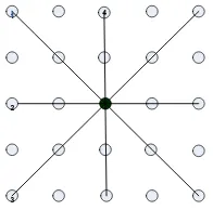
Before introducing the new impulse detector, it is assumed that, a local noise-free image consists of smoothly varying regions separated by edges. Here, the focus is on the edges aligned with four main directions as shown in Figure 1.
1 4
2
[image:2.595.382.480.414.511.2]3
Fig 1. The four directions for impulse detection
Let Sk k = 1 to 4 denotes a set of coordinates aligned with
the kth direction centered at (0,0). Each direction is explained by the set of coordinates as,
S1= −2, −2 , −1, −1 , 0,0 , 1,1 , 2,2 ,
S2= 0, −2 , 0, −1 , 0,0 , 0,1 , 0,2 ,
S3= 2, −2 , 1, −1 , 0,0 , −1,1 , −2,2
S4= −2,0 , −1,0 , 0,0 , 1,0 , 2,0 . Then, let Sk0= Sk\ 0,0 for all k from 1 to 4. For each direction, define di,j k as the sum of all absolute differences of gray-level values between yi+s,j+t and yi,j with s, t ∈ Sk0.
Before the sum is calculated, the closest pixels to the center are weighted with 2 by considering the fact that, two pixels whose spatial distance is smaller than their gray-level values should be close. A 5X5 window centered at 𝑖, 𝑗 , for each direction, define di,j k as the sum of absolute differences as,
Where,
ws,t= 2 s, t ∈ Ω
3, and Ω3 s, t ∶ −1 ≤ s, t ≤ 1
1 otherwise (3) where, di,j k is denoted as direction index and is sensitive to an edge in a different direction. For impulse detection, the minimum of the computed four sums is used, which is written as,
𝑟𝑖,𝑗 = min di,j k : 1 ≤ k ≤ 4 (4)
The value of 𝑟𝑖,𝑗 for the following three cases can be defined
as, (a) When the current pixel is a flat region pixel, 𝑟𝑖,𝑗 is
small, because of the four small direction indices. (b) When the current pixel is an impulse, 𝑟𝑖,𝑗 is large, because at least
one of direction index is small. (c) When the current pixel is an impulse, 𝑟𝑖,𝑗 is large, because of the four large direction
indices. From the above analysis, the current pixel is identified as noisy pixel by employing a threshold T,
yi,j is a
noisy pixel , 𝑖𝑓 𝑟𝑖,𝑗 ≤ 𝑇
noise − free pixel, if ri,j ≤ T (5)
Therefore, a binary flag map is generated from the impulse detection procedure. In the resulting binary flag map, let fi,j represents the flag value on position of i, j . For each pixel yi,j, if 𝑦𝑖,𝑗 = noisy pixel , set fi,j= 1, otherwise, yi,jis
considered as a noise free pixel and for that set fi,j= 0.
After impulse detection, the median based filter replaces the noisy pixel by median value in predefined window of appropriate size. In this technique, the output of the directional weighted median (DWM) filter is used to restore the damaged pixels. In the filter window, a standard deviation is computed to determine the similarity along all the directions which suggests a possible diagonal edge. The information derived from the four directions is used and calculate the standard deviation σi,j k of gray levels for all yi+s,j+t with s, t ∈ Sk0 k = 1 to 4 , respectively. Let,
li,j= argmin k σi,j
k ∶ k = 1 to 4 σ i,j
k (6)
Where, the operator argmin determines the minimizer of a function.
Since standard deviation describes how tightly all the pixel values are clustered around the mean in the set of pixels, li,j
shows that the four pixels in the window aligned with this direction are closest to each other. In order to keep the thin lines and edges intact, the center value should also be close to them. Therefore, proper weights are assigned to the pixels aligned with this direction. Then, the median value of pixels in filter window along the direction found from the previous computation is used to replace the center noisy pixel as the estimated value given by,
mi,j= median ws,t yi+s,j+t: s, t ∈ Ω3 (7)
Where,
ws,t= 2, s, t ∈ Sli,j 0
1 otherwise (8)
and the operator denotes repetition operation. Now with all above notations, it can be written as,,
ui,j= αi,jyi,j+ 1 − αi,j mi,j (9)
Where, αi,j=
0, ri,j> 𝑇
1 ri,j≤ T (10)
3.
RESULTS AND DISCUSSION
Suppressing high Random Valued Impulsive Noise is far more difficult than suppressing fixed-valued impulse noise since for the latter, the differences in gray levels between noise-free neighbors and a noisy pixel are significant most of the times. In this paper, a Directional Weighted Median filter and conventional median based filter techniques have been employed to suppress both high random valued impulse noise (RVIN) and Fixed Value salt and pepper noise. To evaluate the performance of the method, extensive simulations are conducted on Lena and Mandril images. Finally, all the algorithms are implemented recursively, that is, the estimate of the current pixel is dependent on the previously processed pixels.
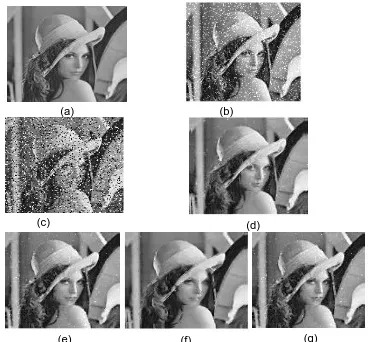
To carry out the simulations, the test images are corrupted by adding impulse noise to them. The images are corrupted at different noise densities. Two methods have been employed to generate the noise images. In the first method, the Fixed Value Impulse Noise (SPN) noisy images are generated by using built-in function (imnoise) and RVIN corrupted images are generated using MATLAB code(using 'randi' built-in function) for different noise densities. Here, the noise is usually quantified by the percentage of corrupted pixels. For example, if an image is corrupted by 30% impulse noise, then 15% of the pixels in the image may be corrupted by positive impulses and 15% of the pixels may be corrupted by negative impulses. In the impulse detection, the influence of the number of thresholds and the threshold values T are first investigated. Based on the heuristic approach, different threshold values are considered for the experimental simulations for each of the test image. In carrying out simulations, for the majority of test images, the most suitable threshold value employed by the filter is approximately T=60 and subsequently the threshold value is decreased by 5 for three to four iterations so that best results are obtained and larger PSNR values are achieved. In all simulations, a filtering window of 5x5 size slides from pixel to pixel in raster scanning fashion. Following this, the impulse noise images are corrected using conventional median based method and Directional Weighted Median method. Figure 2 illustrates the images of Lena for random valued impulse noise (RVIN) and Fixed Value salt and pepper noise introduced using 'imnoise' and 'randi' MATLAB functions and corrected images using conventional median based method and Directional Weighted Median method.
(b)
(c) (d)
(e) (f) (g)
(a)
Fig 2. (a) Original Lena Image. (b)Random Valued Impulse Noise (randi built-in function-MATLAB). (c) Salt
and Pepper Noise (imnoise built- in function-MATLAB). (d) Restoration using DWM method (From RVIN Corrupted Image). (e) Restoration using Con.Median method(From RVIN Corrupted Image). (f) Restoration of
[image:4.595.328.515.71.222.2]using DWM method (From Salt and Pepper Noise Corrupted Image). (g) Restoration of using Con.Median method (From Salt and Pepper Noise Corrupted Image).
Table 1. Property values of Rayleigh channel
Rayleigh channel
ts, the sample time of the input signal
1e-3
fd, the maximum Doppler shift, in hertz
100
Path Delays in Secs 0 1e-5 1e- 5 1e-5 1e- 5 1e-4 1e- 4
Average Path Gain in dB -6 -2 -5 -10 -8 -5 -10
(b)
(c) (d)
(a)
Fig 3. (a)Original Lena Image. (b)Rayleigh channel received image.(c)Restoration using DWM method.(d)Restoration using Con.Median method.
(a)
(c) (d)
(e) (f) (g)
(b)
Fig 4. (a) Original Mandril Image. (b)Random Valued Impulse Noise (randi built-in function-MATLAB). (c) Salt
and Pepper Noise (imnoise built- in function-MATLAB). (d) Restoration using DWM method (From RVIN Corrupted Image). (e) Restoration using Con.Median method(From RVIN Corrupted Image). (f) Restoration of
using DWM method (From Salt and Pepper Noise Corrupted Image). (g) Restoration of using Con.Median method (From Salt and Pepper Noise Corrupted Image).
Mandril image is considered with the same noise effects as explained above. The restored images from DWM and conventional median algorithm are illustrated in Figure 4 and Figure 5.
[image:4.595.73.259.72.243.2]Fig 5. (a) Original Mandril Image. (b) Rayleigh channel received image. (c)Restoration using DWM method.(d)Restoration using Con.Median method.
Table 2. Comparison of restoration results in PSNR (dB) Lena Image (131x131 Size)
Noise Level
RVIN DWM
RVIN SPN
RVIN Conv.Median
SPN Conv.Median 10% 2.5504 30.0250 32.9804 36.9526
20% 33.2068 28.2926 33.4322 31.7737 30% 33.3482 27.9185 34.5319 27.2160 40% 33.9955 26.0481 35.1777 22.9569
[image:4.595.56.275.362.676.2] [image:4.595.323.520.380.531.2] [image:4.595.311.543.598.750.2]Table 3. Comparison of restoration results in PSNR (dB) Mandril Image (131x131 Size)
Noise Level RVIN DWM RVIN SPN RVIN Conv.Median SPN Conv.Median
10% 32.7906 30.0250 0 32.9804 4 36.9526 20% 32.7617 28.2926 33.4322 31.7737 30% 33.4588 27.9185 34.5319 27.2160
40% 33.6242 26.0481 35.1777 22.9569 50% 34.6844 23.4756 36.4347 19.6487
Table 4. Comparison of restoration results in Mean Absolute Error (MAE) Lena Image (131x131 Size)
Noise Level RVIN DWM RVIN SPN RVIN Conv.Median SPN Conv.Median
10% 1.1990 2.1016 1.0085 0.4813 20% 1.3214 2.6293 0.9791 1.0630 30% 1.0617 3.1406 0.8132 1.9829 40% 0.8487 4.0424 0.7445 3.8860
[image:5.595.331.527.238.341.2]50% 0.7790 5.5338 0.5996 6.7857
Table 5. Comparison of restoration results in Mean Absolute Error (MAE) Mandril Image (131x131 Size)
Noise Level RVIN DWM RVIN SPN RVIN Conv.Median SPN Conv.Median
10% 1.4589 2.9657 1.1199 0.6630 20% 1.6142 4.0582 2 1.0510 1.2718 30% 1.3539 3.5739 3 0.9934 2.6031 40% 1.6420 4.4593 0.8649 4.1059
50% 1.2241 5.7091 0.7590 7.0830
Fig. 6. Restoration Results in PSNR (dB) for Lena Image
[image:5.595.333.532.374.487.2]Fig.7. Restoration Results in PSNR (dB) for Lena Image
Fig. 8. Restoration Results in PSNR (dB) for Lena Image
Fig. 9. Restoration Results in PSNR (dB) for Lena Image
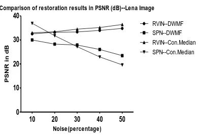
The results DWM filter is compared with conventional median-based method for removal of SPN and RVIN images generated by various means. Figure 6, Figure 7, Figure 8 and Figure 9 shows the various simulation results for the Lena and Mandril images restored to indicate the performance of evaluation of DWM and conventional Median methods in terms of qualitative performance measures like PSNR in dB and MAE.
Restoration results are quantitatively measured by peak signal-to-noise ratio (PSNR) which is defined as,
PSNR = 10log max(i,j∈𝒜) xi,j
2
1
MN ui,j− xi,j
2 i,j∈𝒜
dB (11)
where ui,j and xi,j denote the pixel values of the restored
image and the original image respectively, and the image size is M-by-N with the coordinates (i, j) in the image domain 𝒜. Mean Absolute Error (MAE) is defined as,
MAE =MN1 i,j∈𝒜 ui,j− xi,j (12)
Comparison of restoration results in PSNR (dB)--M andril Image
10 20 30 40 50
0 10 20 30 40 RVIN--DWMF SPN--DWMF RVIN--Con.Median SPN--Con.Median Noise(percentage) P S N R i n d B
Comparison of restoration results in PSNR (dB)--Lena Image
10 20 30 40 50
0 10 20 30 40 RVIN--DWMF SPN--DWMF RVIN--Con.Median SPN--Con.Median Noise(percentage) P S N R i n d B
Comparison of restoration results in M AE--M andril- Image
10 20 30 40 50
0 2 4 6 8 RVIN--DWMF SPN--DWMF RVIN--Con.Median SPN--Con.Median Noise(percentage) M e a n A b s o lu te E rr o r (M A E )
Comparison of restoration results in M AE--Lena- Image
10 20 30 40 50
[image:5.595.50.283.454.741.2]Table 4 and 5 show the various simulation results listed for the Lena and Mandril images corrupted using MATLAB built-in functions and restored to indicate the performance of evaluation of DWM and conventional Median methods in terms of MAE. It can be observed that some pixels are detected wrongly. The pixels detected wrongly are mainly those pixels that are in consistency with their neighboring pixels, and are even difficult to distinguish with human eyes. So, they will cause little effect on the following error correction. The results obtained from the simulations confirm the efficiency of the proposed method.
4.
CONCLUSION
We have attempted to implement a new inpainting algorithm based on Directional Weighted Median filter. The proposed method uses the median of the pixels in a predefined size window in different directions to inpaint a damaged region. The algorithm is fast, simple to implement and provides adequate results in both smooth regions and high contrast edges. The algorithm is iterative and according to our experimental results, it converges at most in 2 or 3 iteration for simple damaged regions. For complex damaged image regions, a larger number of iterations will be required. It is also observed from the simulations that a single threshold value does not serve the purpose as well in different noise conditions. It can be concluded that an optimum threshold value may detect noisy pixels and the correction algorithm considered in the paper would provide very good results for all kind of images considered.
5.
REFERENCES
[1] M. Bertalmio, G. Sapiro, V. Caselles, and C. Ballester, “Image inpainting,” Proceeding of SIGGRAPH., computer graphics processing. pp. 417-424, 2000. [2] M. Oliveira, B. Bowen, R. Mckenna, Y. S. Chang, “Fast
digital image inpainting,” in proc. VIIP2001, pp. 261-266, 2001.
[3] Lin Yin, Ruikang Yang, Moncef Gabbouj, and Yrjo Neuvo, "Weighted Median Filters: A Tutorial", Circuits and Systems Exposition, IEEE Transactions on Circuits and Systems-11: Analog and Digital Signal Processing, Vol. 43, No. 3, pp.157-192 March 1996.
[4] Eduardo Abreu, Michael Lightstone, Member,IEEE, Sanjit K. Mitra, Fellow IEEE, and Kaoru Arakawa, “ A New Efficient Approach for the Removal of Impulse Noise from Highly corrupted Images” IEEE Transactions on Image Processing, vol. 5 , No. 6, pp.1012 – 1025 June 1996.
[5] H.M. Lin and A. N. Willson. "Median filters with adaptive length.", IEEE Transactions on Circuits and Systems, 35: pp.675-690, June 1988.
[6] T. Chen and H. R. Wu. "Adaptive Impulse Detection Using Center-Weighted Median Filters", IEEE Signal Processing Letters, vol. 8 , No. 1: pp.1 – 3, January 2001. [7] Yiqiu Dong and Shufang XU, ”A New Directional Weighted Median Filter for Removal of Random - Valued Impulse Noise,” IEEE PROCESSING LETTERS, Vol.14, No. 3 , pp.193–196, March 2007. [8] Zong Chen and Li Zhang, "Multi-stage Directional
Median Filter", World Academy of Science, Engineering and Technology Vol:35, pp.11-27, 2009.
[9] H.Noori, Saeid Saryazdi,”Image Inpainting Using Directional Median Filters”, IEEE International Conference on Computational Intelligence and Communication Networks, pp.45-49,2010.