A Novel Adaptive Beam forming RLMS Algorithm for
Smart Antenna System
M.Kamaraju,
Ph.DProfessor & Head, Dept.of ECE Gudlavalleru Engineering College,
Gudlavalleru, A.P
K.Ramakrishna
M.Tech, DECS Branch Gudlavalleru Engineering College, Gudlavalleru, A.PK.Ramanjaneyulu,
Ph.D Professor, Dept. of ECE PVP Siddhartha Institute of Technology, Vijayawada, A.PABSTRACT
The smart antenna is a technology and has been applied to the cellular and mobile communication system. It is a combination of multiple antenna elements with a signal processing capability to optimize its radiation and/or reception pattern automatically change in response to the signal environment. The core of smart antenna is the selection of smart algorithms in adaptive array. In this paper, RLMS based adaptive beam forming algorithm is used to improve the performance of the cellular and mobile communication system. Using adaptive beam forming algorithm, the weights/coefficients of antenna arrays are adjusted to form adaptive beam with the required characteristics to track corresponding users automatically and at the same time to minimize interference arising from other users by introducing nulls in their directions.
Recursive Least Mean Square (RLMS) algorithm provides a comprehensive and detailed treatment of the signal model used for beam forming. The performance of the RLMS algorithm in the presence of Multi-path effects and multiple users is analyzed using Software simulations. In the proposed method, mean square error is reduced and Convergence is improved in compared with LMS algorithm based method.
Keywords
Smart antenna, LMS, RLMS, Convergence Rate, mean square error
1.
INTRODUCTION
In future, wireless mobile communication systems will be more sophisticated and wider spread. This growth has triggered an enormous demand not only for capacity but also better coverage and higher quality of service. Smart antenna is one of the most promising technologies that will enable a higher capacity in wireless networks by effectively reducing multipath and co-channel interference. This can be achieved by focusing the radiation only in the desired direction and adjusting itself to changing traffic conditions or signal environments. Smart antennas are also known as adaptive array antennas. Smart antennas or adaptive arrays those are dynamically able to adapt to the changing traffic requirements. Smart antennas are used at the base station, radiates narrow beams to serve different users. As long as the users are well separated spatially same frequency can be reused, even if the users are in the same cell [1]. The process of combining the signals and then focusing the radiation in a particular direction is often referred to as digital beam forming [2]. It is mainly used to calculate beam forming vectors and to track & locate the antenna beam on the mobile target device. The antenna could be optionally any sensor. smart antennas can be used to achieve different benefits. The most important is higher network capacity. It increase network capacity by precise control of signal nulls quality and
mitigation of interference combine to frequency reuse [3]. It increases revenues of network operators and gives customers less probability of blocked or dropped calls. Adaptive Beam forming is a technique in which an array of antennas is exploited to achieve maximum reception in a specified direction by estimating the signal arrival from a desired direction (in the presence of noise) while signals of the same frequency from other directions are rejected.
In this paper, we propose a simple and novel adaptive algorithm for smart antenna, Generally LMS algorithm is used in adaptive filter due to its relatively low complexity, good stability properties, and relatively good robustness against implementation errors. However, the least mean square (LMS) algorithm has slow convergence, which reduces the system performance. In order to increase the convergence rate, LMS algorithm is modified by recursively, which is known as Recursive Least Mean Square Algorithm (RLMS). In our work, we adapt the Interference, RLMS algorithm is proposed to improve the convergence rate and error reduction.
2.
SMART ANTENNA
Smart antenna is an array of antenna elements connected to a digital signal processor; such a configuration dramatically enhances the capacity of a wireless link through a combination of diversity gain, array gain, and interference suppression. Increased capacity translates to higher data rates for a given number of users or more users for a given data rate per user [3]. In addition, wireless communication systems with interference due to frequency reuse. Research efforts investigating effective technologies to mitigate such effects have been going on for the past twenty five years, as wireless communications are experiencing rapid growth [3].
2.1
Functions of Smart Antenna System
The smart antenna consists of mainly two functions
Direction of arrival (DOA) estimation Beam forming
The smart antenna system estimates the direction of arrival of the Signal.
3.
ADAPTIVE BEAM FORMING
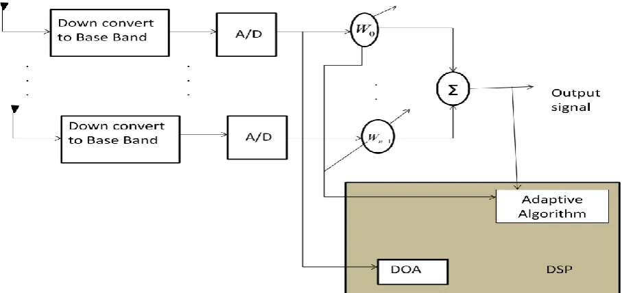
Block diagram of adaptive antenna system shown below Figure1. Adaptive beam forming is a commonly employed technique that enables system operation in an interference environment by adaptively modifying the System’s antenna pattern so that nulls are generated in the angular locations of the interference sources. This approaches applicable to scenarios where multiple antenna elements are individually weighted to produce a desired directivity pattern. In certain
applications the gain of a single antenna may not sufficient. Adaptive beam forming can be performed in many ways using adaptive algorithms. Most of the algorithms are concerned with the maximization of the SNR [7]. Adaptive array systems can locate and track signals (users and interferers) and dynamically adjust the antenna pattern to enhance reception, while minimizing interference using signal processing algorithms.
[image:2.595.72.526.194.408.2]
Fig 1: Block diagram of an Adaptive Antenna System
After the system down converts the received signals are again convert in to baseband and digitizes them, it locates the signal of interest (SOI) using the DOA algorithm, it continuously tracks the SOI and signal not of interest (SNOI)s by dynamically changing the weights (amplitudes and phases of the antenna elements). Basically the DOA computes the direction-of-arrival of all signals by computing the time delays between the antenna elements. Adaptive arrays are generally more digital processing intensive and require a complete RF portion of the transceiver behind each antenna element; they tend to be more expensive than switched-beam systems.
4.
ADAPTIVE BEAM FORMING
Beam forming or spatial filtering is signal processing technique used in sensor arrays for directional signal transmission or reception. This can be achieved by combining the elements in phased array. A phased array is antenna array in which the relative phases of the respective signals feeding the antennas are varied in such a way that the effective radiation pattern of the array is reinforced in a desired direction and suppressed in undesired directions. In such a way that the signals at particular angles experience constructive while others experience destructive interference. Beam forming is the term used to describe the application of weights to the inputs of an array of antennas [2] Beam forming can be used at both the transmitting and receiving ends in order to achieve spatial selectivity.
communications, radio astronomy and acoustic. Adaptive beam forming is used to detect and estimate the signal-of-interest at the output of a sensor array by means of optimal (e.g., least-squares) spatial filtering and interference rejection
4.1
LMS Algorithm
An adaptive filter is a transversal filter trained by an adaptive algorithm. The output response of the uniform linear array is given by
)
(
)
(
n
W
X
n
Y
H (Eq.1)Where w is the complex weight vector and X is the received signal vector given. An error, ε (n) is written as
)
(
)
(
) ( *
n
X
W
n
d
Hn
(Eq.2)Where d(n) denotes the sequence of reference or training symbols known a priori at the receiver at time n.
In a standard LMS algorithm, the weight updated equation given below [5].
)]
(
)
(
)
(
)[
(
)
(
)
1
(
n
W
n
X
n
d
n
X
n
w
n
W
(Eq.3)of fast-changing signal characteristics and the high sensitivity to the Eigen value distribution of the co variance matrix of the array signals.
4.2
RLMS Algorithm
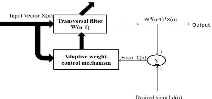
RLMS Algorithm is a linear adaptive filtering algorithm, which, in general, consists of two basic process i.e., filtering process and adaptive process. In filtering process, which involves computing the output of the linear in response to an input signal and generating an estimation error by comparing this output with a desired response. In the adaptive process, this involves the automatic adjustment of the parameters of the filter in accordance with the estimation error filter. The Recursive least square (RLS) Algorithm which is recursively finds the filter coefficients that minimize a weighted least square cost function relating to the input signals. The block diagram of RLMS Algorithm is shown figure 2.
The Adaptive Beam forming using Recursive least mean square algorithm consists of multiple antennas and complex weights, the function of which is to amplify (or attenuate) and delay the signals from each antenna element and a summer to add all of the processed signals, in order to tune out the signals of interest. The output response of the uniform linear array is given by [3]
)
(
)
1
(
)
(
n
W
n
X
n
Y
H
(Eq.4)Where w is the complex weight vector, X is the received signal vector and H is the Hermit an Transpose. The error
signal ε is used by the beam former to adaptively adjust the complex weight vector w so, that the mean squared error (MSE) is minimized. The error is given by
)
(
)
(
) ( *n
y
n
d
n
(Eq.5)The most inherent capacity of RLS is its high convergence Rate [7]. The algorithm updates the autocorrelation matrix for the next instant with the aid of the autocorrelation matrix calculated for the present instant. The RLS weight update Equation is
)]
1
(
)
(
)
(
)[
(
)
1
(
)
(
n
w
n
g
n
d
n
X
n
w
n
w
(Eq.6)Where g(n) is the gain vector of the standard RLMS Algorithm. The RLMS Algorithm offers an alternative to the LMS Algorithm as a tool for the solution of adaptive filtering problems. It gives highest convergence rate because the error at any point of time is independent of the statistical properties of the signal. The advantage of RLMS Algorithm is all the array data information that obtained after the initiation of the algorithm and using iteration method to realize the inverse operation of the matrix, so the convergence rate is rapid. It is not sensitive to Eigen value distribution [8]. The steady state value of the ensemble average squared error produced by the
[image:3.595.117.479.381.551.2]RLMS Algorithm much smaller than LMS Algorithm.
Fig 2: Block diagram of RLMS Algorithm
5.
SIMULATION RESULTS
The performance of Adaptive smart antenna system using RLMS Algorithm givesthe improvement of convergence rate and error reduction of Adaptive array antenna system. It is slightly better than LMS Algorithm. Finally, The RLMS algorithm converges much more quickly than the LMS algorithm.
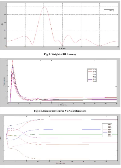
Figure 3 it is considered that the Arriving angle and interference elements are 8 with spacing between the elements is 0.5λ. In this the amplitude level angles are 30, 40 degrees with the different signal strengths. No of the signal does not
varied from LMS to RLMS due to this convergence rate are improved.
Figure 4 it is considered that the no of iterations are 50, no of elements 8 and element spacing is 0.5λ. It should maintain the constant step size to reduce the mean squared error. Almost it gives the minimum mean square even when the iteration no increases.
Fig 3: Weighted RLS Array
Fig 4: Mean Square Error Vs No of iterations
Fig 5: Acquisition and tracking of desired signal
5.1
Comparison of results
Figure 6 shows the comparative view of LMS and RLMS algorithm in terms of acquisition and tracking of desired signal. Here step size of LMS algorithm is varied, because it is most sensitive of all parameters to quantizations. In the case of RLMS algorithm the step size is fixed due to this tracking of desired signal is improved compare to LMS algorithm.
In LMS algorithm the no. of array elements increases, the
lack of array elements present in the LMS algorithm. Where as in the case of RLMS algorithm the no. of array elements increases, interference angle and arriving angle’s are not varied, because it is not sensitivity to Eigen value distribution of array elements as illustrated in figure 7.
Fig 6: Acquisition and tracking of desired signal
Fig 7: Weighted RLS Array
s
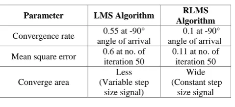
[image:5.595.91.506.321.698.2]Table 1. Comparison of LMS and RLMS algorithms
Parameter LMS Algorithm RLMS
Algorithm
Convergence rate 0.55 at -90° angle of arrival
0.1 at -90° angle of arrival
Mean square error 0.6 at no. of iteration 50
0.11 at no. of iteration 50
Converge area
Less (Variable step
size signal)
Wide (Constant step
size signal
6.
CONCLUSION
The Conclusion of the narrow beam of smart antenna can be steered towards the desired direction by steering beam angle, keeping element spacing 0.5λ, number of elements n and altering weights w(n) adaptively. In The Recursive least mean square algorithm by increasing the number of iterations mean square error is reduced and tracking of desired Signal is improved. Convergence rate and coverage area is also improved in RLMS algorithm.
7.
REFERENCES
[1] K.R.ShankarKumar* and T.Gunasekaran**“Performance Analysis of Adaptive Beam forming Algorithms for Microstrip Smart Antennas”Technical -International Froehlich, B. and Plate, J. 2000. The cubic mouse: a new device for three-dimensional input. In Proceedings of the SIGCHI Conference on Human Factors in Computing Systems
[2] Hemanth kumar naik.B*, B.V.N.R Siva Kumar**, Bharat Kumar.A*** “performance of adaptive beam forming Techniques in smart antenna” International Journal of Engineering Research and Applications (IJERA) Vol. 2, Issue 3, May-Jun 2012, PP 1333-1336 13.
[3] Prof.B.G. Hogade*,Ms. Jyoti Chougale-Patil**,Dr.Shrikant K.Bodhe*** “Analysis of Improved and Traditional LMS Beam forming Algorithm for Smart Antenna” International Journal of Engineering Research and Applications (IJERA) Vol. 2, Issue 3, May-Jun 2012, PP.1816-1820
[4] D. B. Salunke*, R. S. Kawitkar** “Analysis of LMS, NLMS and MUSIC Algorithms for Adaptive Array Antenna System” International Journal of Engineering and Advanced Technology (IJEAT), Volume-2, Issue-3 February 2013, PP 130-133
[5] Muhammad Salman Razzaq* and Noor M. Khan** “performance comparison of Adaptive beam forming algorithms for smart antenna systems” ISSN 1818-4952 World applied sciences journal 11 (7) IDOSI Publications, 2010 PP 775-785.
[6] G.V.S. Karthik1*, Md. Zia Ur Rahman**, T. *** “Algorithm for steering Smart Antennas: An Application to Wireless Communications” International Journal of Research and Reviews in Wireless Communications (IJRRWC) Vol. 1, No. 3, September 2011, PP-37-42.
[7] Jian-wu zhang* “The adaptive algorithms of the smart antenna system in future systems” journal of IEEE Publications 0-7803-8842-9/05/S$20.00 2005 PP 347-350.
[8] Text book “Adaptive Filter Theory” Simon haykin and Thomas kailath (series editor)