Models, AmI-Creator and A-Methodology for
Ambient Intelligence Environments
Anna Chambers
Menai Bridge, UKEmail: [email protected]
Received 4 February 2014; revised 1 March 2014; accepted 8 March 2014
Copyright © 2014 by author and Scientific Research Publishing Inc.
This work is licensed under the Creative Commons Attribution International License (CC BY).
http://creativecommons.org/licenses/by/4.0/
Abstract
The current paper introduces an approach to a development of Ambient Intelligence domain- based software systems from scratch. The presented approach is based on models. The paper also presents the domain-related models expressing different levels of abstractions and stages of the development. The approach refers to a Model-Driven Development of Ambient Intelligence which was suggested at AmI-07-Ambient Intelligence conference. The approach is presented as a stan-dard with its feasible realization. It starts from modeling of a content of the future AmI-dedicated software system and concludes by mapping the graphical concepts into a final code. A process proving feasibility and correctness of the approach is provided through a dedicated research me-thodology. Its process comprises an identification of needs in a speedy development of the sys-tems. It is followed by studying of the currently available techniques capable of supporting the development and an experimenting with them. It continues by finding a solution, verified by its validation and concludes by an identification of the further perspectives. The developed approach presents a common way of a communication amongst stakeholders participating in creating of AmI-based environments. Such communication involves the notations of AmI-Creator—a Domain- Specific Language of Ambient Intelligence domain. Every part of DSL corresponds to a demonstra-tion of A-methodology expressing a step-by-step guidance for the development. The methodology comprises two parts dedicated to providing semantics for DSL through studying of Ambient Intel-ligence domain ontology; and development of actual environments. A validity of the working proposition is confirmed by three examples. The further challenges refer to an extension of the presented work by other frameworks and expansion to a development of different domains with complex organizations.
Keywords
eration of different Software development methodologies. It demonstrates an inference of a common way of communications amongst the stakeholders participating in the software development process expressed in nota-tions of AmI-Creator—Domain-Specific Language (DSL) for the development of AmI-based environments (AmI-E). The semantics of the language syntax corresponds to the semantics of the AmI concepts. Such concepts are pre-sented in ontology of AmI domain expressed in various notations for their future reuse. For example they can be used for an initial analysis of the problem or for expressions used in the final code.
This paper also shows a set of models expressing different aspects and stages of the AmI-E development process. These stages are summarized in A-methodology structure of which is based on A-MDA (Adapted MDA) and MDD. A use of a MDD-based methodology allows a production of an entire flow of the software develop-ment process. It starts from an identification of the requiredevelop-ments and finalizes with the end code expressed in (Java) programming language notations. The main outcomes of the presented research comprise:
Adapted Model-Driven Architecture (A-MDA).
Methodology for the development of AmI-E from scratch. Ontology of AmI environments.
AmI-Creator-DSL for the development of AmI environments.
The feasibility of the presented research is verified, validated at the appropriate stages and tested on different applications.
The current research presents a standalone idea, equivalent of which was not met in the preceding literature survey. The research evaluates the survey’s finding and brings forward its argument declaring AmI as a separate domain on its own rights. This domain has the common indistinguishable parts. The development of the soft-ware-based systems from this domain can be based on a typical methodology.
The reminder of this paper shows the reason why the new approach to the AmI development is required. It also describes how it is created, realized, verified, evaluated and tested. The paper suggests a use of such ap-proach for other domains. The paper’s content covers the descriptions of:
1) Approach to the current research.
2) Overview of the existing AmI and SE related developments. 3) Demonstration of an adaptation of MDA.
4) AmI domain concepts, ontologies and DSL. 5) Description of the horizontal set of models.
6) Evaluation (through Verification, Validation and Testing). 7) Conclusion and further work.
2. Approach to the Current Research
This part describes an analysis of a central research problem and its focus. It also shows a structure of the
pro-1AmI-07 at http://ami-conferences.org/2007/index.html on 09.01.2011 2
Model-Driven Development at http://msdn.microsoft.com/en-us/library/aa964145.aspx 3OMG Model Driven Architecture at http://www.omg.org/mda/
(MDA) and Domain-Specific Language (DSL). MDA refers to a structure, whereas DSL implies various nota-tions of different concepts.
An initial studying of AmI domain discovered two core subjects comprising Conceptual model and Ontolo-gies. Conceptual model comprises a set of interconnecting concepts. Ontology provides semantics and notations of the concepts and their interconnections in different representations. Ontology is dedicated to a specific reuse for specific purposes. Concretely, ontology of AmI domain comprises a set of various features characterizing the domain; which current research considers as a specific physical entity (or environment).
A further consideration of the existing AmI-related research indicated a lack of common (typical or standard) approaches to a development of AmI systems. Regarding to these, the current research declares a hypothesis as-serting an existence of the approach. It shows the proof of a feasibility of such hypothesis.
The main focus of the current research concerns a development of AmI environments based on Model-Driven Development. The research puts forward an idea of using models for the development of AmI. It argues that the research proposes a standard way of intercommunications among stakeholders participating in the development of AmI software systems from scratch.
2.2. The Proposed Solution
A realization of the hypothesis peruses two separate objectives. The first refers to a consideration of Ambient Intelligence as a domain characterized by a set of common entities. Such entities refer to a set of basic elements participating in building of AmI-based software systems. The second objective refers to an obtaining of a step- by-step development of such systems.
The set of tasks leading to the objectives refers to two typical sets of activities (or methodologies). The first objective of these is to be devoted to the development of AmI domain (as a set of the standard concepts). The second is to be dedicated to the development of new AmI-based environments. The sequence of both of the sets is based on A-MDA, resulted in A-methodology comprising Vertical and Horizontal parts. The completion of the Vertical part of the methodology assures feasibility of the Horizontal part, completion of which is finalized in code.
The progression of the outlined solution requires the various activities and techniques e.g. collecting neces-sary information, its analysis, taking decision on the incoming tasks, verification and valuation of the data have gotten.
2.3. The Current Research Methodology
The current research methodology comprises a combination of variations of qualitative methodology, which de-pends on the context of the particular stage of the research. It is also updated with additional methods used by the other researches to evaluate and test the appropriate outcomes summarized in the Table 1.
3. Overview of the Existing AmI and SE Related Developments
This section demonstrates the latest updates in the field of AmI and general software development. The updates are summarized in three hundred twenty seven on-line publications for a period of 2005-2010. The section com-prises two parts. The outcome from the first part comcom-prises clarification of the research question. Outcome of the second part comprises providing a background for the proposed solution of the specified problem.
3.1. The First Part of the Survey Discovered the Following Issues
3.1.1. AmI-Related Overview“personal health” and “ambient assisted living”.
The AmI definitions vary. They include such notions as Ubiquitous/Pervasive/Proactive/Ambient Computing, Calm Technology and Smart Environments [7]. The interpretations and visions refer to “multidisciplinary para-digm” [8] and “vision of future Information Society” [9].
Summarizing the information ([10] [11], MIT cited in [12]-[14]), the current research indicates that the idea behind AmI refers to the set of interconnecting devices working together in the intelligent way. AmI can serve humans’ tasks of “putting a technology on people’s services and for their benefits” [13]. The devices facilitate an electronic (or digital) environment. The information indicates a sharing of the basic assumptions about AmI properties and a way of their composition for the behaviors in an intelligent or “smart” way. For example the properties of ubiquity and disappearance refer to challenges of design interactions in future smart environments [7].
The ubiquity refers to an increasing number of computers around us, their incorporation in different parts of our environments and becoming a part of our life by maintaining everyday routines.
The disappearance is explained as tendency of computing devices to get smaller and disappear (hiding) in a textile surroundings us. The incorporation of such devices refers to integration of information, communication and sensing technology into everyday life leading to turning of our environments into “smart”. The “smart” concept refers to capabilities of sensing, processing, making decision and actuation, which has to have self-di- rections (e.g. actions or re-action).
The AmI has been understood as a set of entities with different arrangements such as Service-Oriented Archi-tecture [15], structured context information AmbiNet [16], Agent-based architecture ([17] [18]) managing dif-ferent technologies e.g. Wi-Fi, FRID, ZigBe or a coordinated structure of “domotic” components [19] and an architecture for an activity recognition using Visual Sensor Network [20]. The execution of AmI is supported by such technologies as a networked control system (NCS) [21], Near Field Communication Technology [22], and other [3] [23]-[26].
Some of the AmI-related themes refer to ontology of a single activity as a set of tasks [27] or ontologies de-scribing “activities sphere” [19]. Another theme refers to a conceptual model [28] comprising layers of sensors and actuators, a network and a middleware, a device, a service and an AmI application.
Alternatively AmI was realized as middleware comprising different services and facilitating interactions of different parts [15] [29]-[31]. Further AmI-based interface is presented as adaptive interface [32] for complex AmI environments sharing resources (hardware, networks and knowledge); or providing a generation of user in-terfaces for Ambient Assisted Living services based on an interaction framework [33]. “World around us is in-terface to information” refers to AmI context [7]. An AmI context-awareness specifies a nature of a context as spatiotemporal, environmental, personal and social [34]. Ambient Intelligence have been developed by some companies (Opt.Cit. [10] [35]).
The bases for building of AmI were introduced through such examples as AMENITIES methodology [36], 3D-based rapid prototyping [37]; a Product Line Approach [38], Aspect-oriented programming [39].
3.1.2. AmI Environments Issues
envi-It was understood as comprising element or a summation of elements or disciplines. Regarding to the remaining text, the current research reckons that use of term “Environment” is more appropriate to an identification of “Ambient Intelligence” concept as referring to a particular space under an influence of AmI. Ambient Intelli-gence represents an “Intelligent environment which reacts in a sensitive and adaptive way to the presence of different objects in order to provide various services to people” [43].
Having comprehended the information about AmI the current research provides its own definition of Ambient Intelligence as:
Ambient intelligence is Artificial Intelligent Technology-based Environment providing responses on the dy-namically detected requests and satisfying the predefined tasks in the expected way and in the expected time.
Furthermore, Ambient Intelligence was articulated by AmI-085 as a subject of expansion into wider areas. Additionally it was indicated that “engineering such systems is a nontrivial task, and convincing solutions are still missing” [44]. In response to such statement the researches provide different ideas, examples of which comprise an idea of attracting SE (MDD in particular) into the development of AmI. Such idea was articulated at AmI-07. Another idea of using Software Engineering for the development of Ambient Intelligence was sug-gested at AmI.d-076.
Finally the research question is clarified as focusing on proposition of the standard MDD to the development of AmI systems.
3.2. The Second Part of the Survey Discovered the Issues Clarifying What Is Exactly
Involved into the Software Engineering Notion of Model-Driven
Development of AmI-E
The current research identifies context of models as a clear set of formal elements that describe something being developed for a specific purpose and can be analyzed using various methods [45]. Engineering model must in-clude the characteristics of Abstraction, Understandability, Accuracy, Predictiveness and Inexpensiveness.
3.2.1. MDD and SE Concerns
MDD is associated with a notion of Model-Driven Architecture (MDA), which provides a basic terminology for MDSD—Model-Driven Software Development. The current research sees MDD as means supporting a colla-borative discussion among the project’s stakeholders for obtaining an immediate feedback.
There is no agreement among the SE researches on a precise definition and content of MDA. Some of them see MDA as a new approach to writing specifications and application’s development. The developments are based on a Platform-Independent Model (PIM)7 of the application or specification of business functionality and behavior. The other [46] explains MDA as “about using modeling languages as programming languages rather than merely as design languages”. OMG clarifies principles of MDA as (1) the understanding of systems for en-terprise solution laying in the models with well-defined notations; (2) the architectural framework of models, comprising layers and transformations structure, can serve the purpose of building systems; (3) the tools-based basis for an automotive models integration and their transformation; (4) this Model-Driven approach is to be based on industry standards, openness to consumers and encouraging vendors competitions.
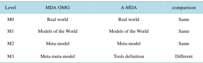
The original MDA OMG is organized into a four-layer architecture [45] which comprises: M3 layer meta-meta-model: MOF-Meta-Objects Facility.
M2 layer meta-modeling: UML profile Custom meta-model.
M1 layer model: UML models, Custom meta-model, Models based on the custom’s meta-models. M0 layer reality: The Real World.
5AmI-08 Conference in Nuremberg at http://www.ami-conferences.org/2008/index.html 6AmI.d 2007 at http://www.strategiestm.com/conferences/amid/07/index.htm
production.
3.2.2. Software Methodologies
Further, SE offers two types of methodologies referring to a step-by-step development process. It also includes such approaches to a general software development, a development of AmI software systems and DSL. The SE methodologies refer to Waterfall, Evolutionary development, Rational-unified process, V or Agile methodolo-gies.
3.2.3. AmI-Dedicated Methodologies
The examples of AmI dedicated approaches and methodologies refer to “Design for all” [50], Universal Access perspective [51], Software product line approach for AmI environments [52]. Other examples ([14] and [53]) outline a process of building AmI environments: starting from needs of sensors and devices for surrounding the environmental inhabitants with technology, where sensors collect different context information which is to be transmitted by a network and pre-processed by middleware. The examples do not describe a sequence of the ac-tivities for building AmI environments. Other examples comprise cooperative system design [54] and design framework [13].
The example refers to rapid prototyping of creating an AmI demonstrator [29]. User-Centered design [55] put forward message: “The design interactive systems, that are targeted to be introduced into the market within a timeframe of five to ten years, remains a methodological challenge”. The current research considers this as a request to a new methodology.
Despite the variety of the approaches, AmI scientists ([56] [57]) state that clear methodology for digital eco-system (or AmI) design does not exists yet. It gives an interesting hint on De Ruyter’s approach through build-ing prototypes to be discussed with stakeholders.
3.2.4. DSL Methodology
The methodologies proposed for the development of DSLs comprise several activities [58], [59]. The current research agrees that prior to the language development the domain should be studied, but it does not agree that the development should start from the syntax definition. In the current research opinion, the developer should study domain initially. It should be followed by an extraction of the semantics corresponding to the appropriate syntax, expressed in different concrete notations. For the current research purpose the notion of DSL is prefera-ble to general purpose programming languages as it can provide domain-specific notations to be used for mod-eling of the different stages of the development. The content of the stages should be discussed with customers and stakeholders.
3.2.5. Request to New Methodologies and AmI Development
me-317 3.2.6. Tools and Languages
Some researches show tools [60] used for developments in AmI such as Ambi Graphs. The syntaxes comprise such notations as boxes, rhombus and arrows. Authors indicated a necessity of the context modeling, analysis and reasoning (cited in [61]). Models are good for expressing requirements, reasoning and discovering anoma-lies, inconsistency and incompleteness.
As things stand above: The proposed solution of MDD in AmI can be realized by means of MDA, explaining the way of obtaining semantics and syntax for DSL called AmI-Creator. It can be supported by the appropriate tools; and methodology comprising the set of steps necessary for the development of AmI systems.
4. Demonstration of Adaptation of MDA
Believing that the development of AmI-E can be unified, standardized and presented as modeling process based on Software Engineering notions of MDA and MDD the current research generates the research hypothesis that:
“The Model Driven Development approach to the development of AmI domain and applications, based on
MDA is possible and can be produced”.
Such hypothesis refers to an inference of a way dedicated to a development of AmI based system from scratch. Focusing on finding a common way of the communication among the stakeholders during the AmI development process the current research puts forward an idea of models. Their semantics should be identified by ontologies. Their syntaxes should be expressed in DSL notations.
The inference of DSL and its concrete use the current research sees through an adaptation of an idea behind MDA. It was generated by the organizations interpreting MDA as an approach to application design and imple-mentation. “As defined by the Object Management Group (OMG), MDA is a way to organize and manage en-terprise architectures supported by automated tools and services for both defining the models and facilitating transformations between different model types.”8 In respect to the generated idea of MDA-based structural ap-proach the author presents a novelty to a creation of AmI applications from scratch. It refers to a realization of the requirements comprising models and tools supporting their production. This idea is developed by the current research.
The hypothesis corresponds to the appropriate theory that MDD is a right approach to the development of AmI-based systems. The current research sees the proof of the theory through a conjunctive consideration of two research fields comprising SE and AmI. The first of them serves the development of the second.
Supporting its theory the current research concentrates on producing the following outcomes:
Outline, structure, production and implementation of the Model-Driven Development Methodology for creating software applications from AmI domain from scratch
Present AmI-Creator—a new Ambient Intelligence-dedicated Domain Specific Language (AmI-d-DSL) Realize IDE (Integrated Development Environment) for AmI, implementing the DSL for AmI
The intended results of the development imply to bring the benefit to the AmI development stakeholders, whether they are developers or not. This benefit would provide the user with a fully developed flow of the de-velopment of AmI applications (finalized in the code realization), supplied with AmI-dedicated language and realized tools.
The current research sees a production of the desired targets as outcomes of a “Walkthrough” of the Adapted MDA (A-MDA) based on the structuring idea behind MDA OMG. From the original idea of MDA the current research adapted only the layered arrangement of solving a problem. The every level of A-MDA is dedicated to a task e.g. domain analysis or study the requirements for the appropriate tools. Comparison of two architectures is shown in Table 2. Despite the similarities of the layers the MDA and A-MDA are differentiated. A-MDA does not pursues the purpose of MDA producing a model of the immediate lower level; but pursues a single purpose of comprehension and sufficiency of needs for modeling and building of AmI environments:
4) The top level realizes the tools’ requirements.
The A-MDA provides a structure for definition of two methodologies comprising methodology for creating of AmI-based DSL (called AmI-Creator) and methodology for the development of software systems from AmI domain.
In respect to the development of AmI-Creator the requirements for A-MDA refer to a providing a base for outlining the process of the development of DSL for AmI environments. It comprises an obtaining of the DSL semantics, a concrete syntax and its supporting tools. The process corresponds to a methodology outlining the sequence of activities. They start from analysis of a domain with extracting a vocabulary (refer to ontology), continue through design (modeling) and finalizes by realization of the supporting tools. The process is based on a technique called “Walkthrough” referring to the step-by-step activities provided at A-MDA levels:
In the reference to M0 (real world of AmI environment):
o Studying the world of Ambient Intelligence Environment.
o Derive the comprising concepts, their relations and intercommunications.
o Summarize findings of studying the domain in (middle) ontologies.
o Extract domain vocabulary (or semantics).
o Document the findings as ontology documents. In the reference to M1 (model of AmI environment):
o Outline the sequence of models and their contents.
o Extract the appropriate semantics expressed in vocabulary for every specified model.
o Specify concrete syntax.
o Document the findings.
In the reference to M2 (meta-model of model of AmI Environment):
o Analyze domain of models of the level M1 and derive the set of models’ comprising concepts.
o Summarize, generalize and abstract them into the general types of modeling entities, capable of creating of any modeling concepts for models in the M1.
o Identify these entities as general types, comprising the concepts (or upper-ontology).
o Define the upper ontology as vocabulary for the next part of AmI-Creator (AmI-DSL). In the reference to M3 (as realization of tools to depict syntax):
o Analyze requirements ensuring full support of the modeling features.
o Give detailed requirements of the working tools.
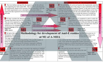
There are two kind of “Walkthrough” were considered at the research: Vertical and Horizontal. Vertical “Walk through” (Figure 1) contains two parts: bottom-up (inferring requirements) and top-dawn (for realization and implementation of the requirements). Horizontal “Walkthrough” (Figure 2) has left-to-right direction out-lining the activities for an application development (at M1) and mapping of the requirements into their realiza-tion (at M0, M2, M3).
The Methodology Description
[image:8.595.129.467.99.204.2]Figure1.Vertical “Walkthrough”.
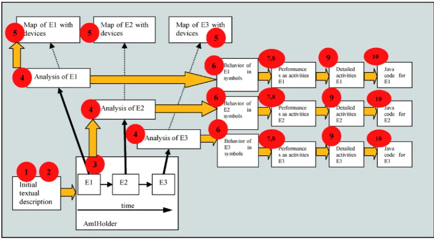
Figure 2. Horizontal “Walkthrough”.
ningful notations and a consecutive development of activities; where the first refers to a DSL and second refers to a methodology.
The inference of the notations complies a vertical “Walkthrough” of A-MDA. It occupies three bottom layers (M0 - M2) and comprises activities of bottom-up (from M0 to M2) and top-dawn (from M2 to M0) directions. Bottom-up activities are dedicated to obtaining of AmI domain concepts, suggestion of language semantics, their abstractions into meta-language semantics and finalized with a deriving of tools requirements. The bottom- up part also suggests the graphical notations. The top-dawn activities comprise: the realization of the appropriate tools capable of holding the appropriate graphical notations, choosing notations for meta-language and DSL. The horizontal part of A- methodology resides at M1 layer of A-MDA and derives the stages for the develop-ment of new AmI domain-based applications. The overall logical structure of the AmI-dedicated developdevelop-ment from scratch forms a shape of capital “A” (Figure 3), after which the methodology was called. The Vertical bo- ttom-up and top-dawn directions provide a background for the implementation of the Horizontal part.
Figure 3.Depiction of inference of A-Methodology.
5. AmI Domain Concepts, Ontologies and DSL
5.1. AmI Domain Concepts
This part demonstrates the step-by-step analysis process. It comprises three stages of initial analysis of the stu-died domain, ontologies as intermediate analysis of the domain for it future reuse. It finalizes by using the on-tology’s concepts as semantics corresponding to the concrete syntax of the concrete DSL. It shows an inference of the modeling concepts to be used in the actual modeling of AmI environments.
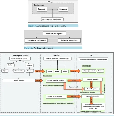
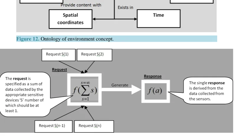
Having studied the AmI examples the current research realizes AmI domain as an entity to be considered from two perspectives. The first perspective refers to the request-response context (Figure 4). The second pers-pective refers to a conceptual model. The last comprises main sets of concepts abstracted into two groups of time-spatial and software components (Figure 5). The request-response perspective implies that some entity perceives a data (or context of the environment). This is specified as a request. The other entity interprets the context and generates an appropriate response. The context model perspective implies an obtaining of a set of the domain concepts (see left part of Figure 6). These are considered as a base for the corresponding AmI on-tologies (see middle part of Figure 6). This perspective demonstrates the way of studying of the domain seman-tics (in a conceptual model and ontologies). They are followed by their expressions in the appropriate language and meta-language referring to the appropriate syntax (see right part of Figure 6).
Having considered and compared the notions of Conceptual model, Ontologies and Domain-Specific Lan-guage the current research found that all three notions showed that they are very close in their ideas. All of them collect and express the domain information, but pursue different purposes:
Concept model is used for studying a domain.
Ontology express a domain concepts and their interconnections in different notations. DSL provide notations for creating of different applications.
Figure 4. AmI request-response context.
[image:11.595.93.536.84.535.2]Figure 5.AmI second concept.
Figure 6.Interconnections between conceptual model, Ontology and DSL.
Three concepts of the Conceptual model represent the abstractions of the AmI domain concepts, derived dur-ing an initial analysis of the domain. They correspond to the concepts of the Middle Ontology. This ontology is mapped into a DSL’s semantics and are represented in the concrete syntax of DSL.
The concepts of the Middle ontology refer to the abstractions of the Lower ontologies, which are mapped into the application’s semantics of a future concrete system. The application semantics correspond and map into the concrete syntax of the Domain-Specific Language which can be represented in graphical and non-graphical no-tations.
One of the non-graphical notations refers to a XML notations, which provide a background for model trans-formation (refer to the further research).
5.2. Ontology
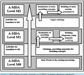
Figure 7. Description of entire activities at A-MDA including obtaining ontologies.
[62]. The current research interest concerns Upper and Middle ontology representing the AmI domain modeling concepts, where Upper ontology considers Generic Common Knowledge and comprises most General Things; Middle Ontology considers Domain Spanning Knowledge.
The way of inference of the ontologies is depicted in the (Figure 7). It demonstrates a use of A-MDA in re-spect of showing the activities at the appropriate levels of the A-MDA. Such, it shows that obtaining the ontol-ogy (refer to middle ontolontol-ogy) of the real world of AmI domain is provided through a studying of the existing AmI representations and applications mentioned in Section 3.
The studying extracts the meaning of the concepts, which were met in the existing examples. Such meanings provide the semantics for DSL-AmI-Creator. Obtaining the Upper ontology is provided through an abstraction of the middle ontology. Its purpose concerns a providing the semantics for basic modeling concepts, which refer to the meta-models and meta-language concepts. Apart from these the A-MDA ensures the activities for obtain-ing the requirements for the software tools. The tools should support the feasibility of the producobtain-ing the nota-tions. The overall approach to an extracting of the semantics for the ontologies from the existing examples is based on the motto:
“Summarize the commonalities and distinguish the differences of AmI-based entities”.
All of the examples showed an existence of the same concepts, containing such notions as Environment (in capacity of a holder of AmI content), Devices intercommunicating through Network, Context providing differ-ent information about the environmdiffer-ent and Time as length of some kind of a process or performance. These re-fer to the properties of AmI domain and present a set of the standard characteristics of AmI domain.
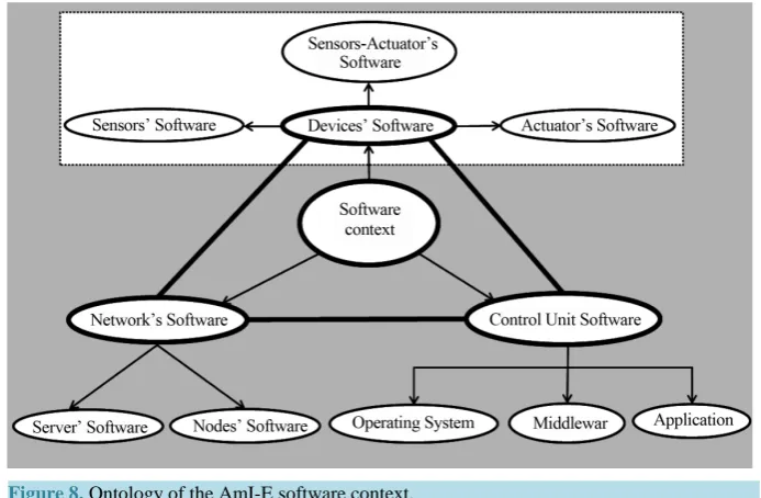
The nature of AmI environments is characterized by two contexts of the physical (or time-spatial) entities and software. The successful work of the AmI environments is supported by the appropriate software. Referring to it the ontology comprises software and time-spatial components (Figure 6). The ontology of the AmI-E software context is represented at the picture Figure 8. It shows that Software context comprises:
Software residing on the Devices including:
o Sensors’ software.
o Actuators’ software.
Figure 8.Ontology of the AmI-E software context.
Software supporting a working Network ensuring a successful work of the interconnecting devices includ-ing:
o Servers’ software.
o Nodes’ software.
Software supporting a work of a Control Unit of the entire AmI system including:
o Software of an Operating system.
o Software of a middleware supporting the logic of the system.
o Software of probable applications e.g. modulator/demodulator.
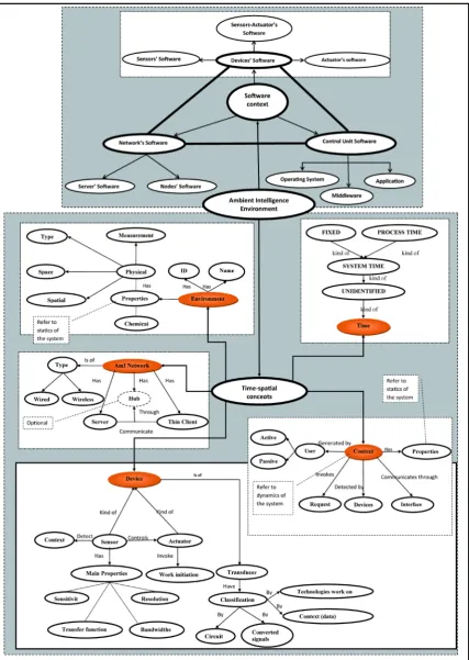
The software component does not participate in the actual building of AmI environments will not be consi-dered in details in this paper. The ontology of the time-spatial context refers to the main focus of building of AmI environments. It comprises a set of the components interconnecting through interfaces as shown in Figure 9. It also depicts the appropriate intercommunications through interfaces. It shows that the concepts of this con-text comprises:
Environment. Network. Devices. Time.
Context of the Environments referring to its different properties.
These concepts (depicted as ellipses) communicate with each other through interfaces, which can be of hands- free (depicted in dashed lines) or direct (physical) contact (depicted in solid lines). The directions of the inter-communications are shown as the arrowed lines. For example, it is shown that Environment contains Devices, which are capable of detecting a Context. The pointing down arrow shows that the Context’s data is to be processed, but the actual process is not a concern of the current paper.
Figure 9.Ontology of the AmI-E Time-spatial context.
ties are taking place during some period of time and refer to the notion of process or performance. The research interpretation of the AmI domain is presented in the model of middle ontologies and upper ontologies. They are expressed in forms explaining that Middle ontology of AmI comprises Holder/Environment, Device, Context, Network, Time and Process. The middle ontology is referred to the expression:
= + + + + +
AmI Holder Environment Device Context Network Time Process
The upper ontology of AmI comprises elements of Object, Subject and Process:
= + +
AmI Object Subject Process
The every concept comprising the ontologies has its own properties and can be considered as a domains on their own rights, example of which is depicted in the Figure 12. This particular ontology is intent to be used for analysis purpose. For use in programming the some ontology was expressed in Java notations for example:
public class Environment{ private String Name; private int ID; private String type;
AmIMeasurements [][][] amMeasure; AmICoordinates [][][] amICoord; AmIContext[] amIContext; AmIDevice[] amIDevice; AmINetwork[] AmINetwork; AmITime[][][] amITime; pulic r_type performance()
{//methods can referto UserRequest}
Regarding to the both of the contexts the research presents a mathematical representation of AmI domain (Figure 13). The picture explains that response is generated as reaction provided by the system on a particular state of the environment. The state is based on the particular values of the environmental characteristics referred to the context. The equitation demonstrates a general representation of the idea behind a request-response con-cept of AmI.
Figure 11. Nested ontology of AmI-E.
Figure 12. Ontology of environment concept.
Figure 13. Mathematical model of AmI domain.
[image:16.595.101.498.433.663.2]summarized number of performed actions in responses to the set of calculated requests (value of sensing data). The requestes are obtained from the sensors, allocated to the specified coordinates at the detected time t0”. This equitation indicates that AmIHolder can comprise an unlimited number of sensors, actions, networks and environments. It also refers to one of the version of the AmI ontologies represented in the form of mathematical notations. Such can be reused for the identification of the precise components of the future AmI systems, explaining the nature of AmI in the most abstract way.
5.3. DSL Concrete Syntax
The actual DSL with its appropriate concrete syntax corresponding to the development stages (Figure 14) of AmI-Creator (Figure 15) is presented in the following Figures 16-19. The symbolical representations of the AmI-Creator should be used in the development of AmI-E. They include graphical notations, which are employed for the analysis and constructing of the environments. The Java programming notations are used for the implementation or an actual coding. The DSL is explained in the Section 7. The actual figures refer to:
Figure 16 refers to: Concrete syntax of the AmI-Creator DSL for depicing of both: the environments at AmIHolder and overall performance at AmIHolder.
Figure 17 refers to: Concrete syntax of AmI-Creator for coarse organisation of the environments (the first, second and last row show the examples only).
Figure 18 refers to: Concrete syntax of AmI-Creator for realisation of the performances at the different environments.
Figure 19 refers to: Concrete syntax of the AmI-Creator DSL for depicing of more detailed performance at environments.
6. Description of the Horizontal Set of Models
[image:17.595.143.455.517.706.2]Having provided the background for the development of AmI-E software systems, the A-methodology describes the development process at the Horizontal part of A-methodology (or Horizontal methodology). It realizes the development of AmI environments (or systems). The structural flow of such realisation resides on the level M1 of A-MDA and describes the step-by-step methodology of the complete AmI-E development process.
Figure 15. Entire flow of the AmI-E development process.
Figure 16.Concrete syntax of the AmI-Creator DSL for depicting of both: the environments at AmI Holder and overall performance at AmI Holder.
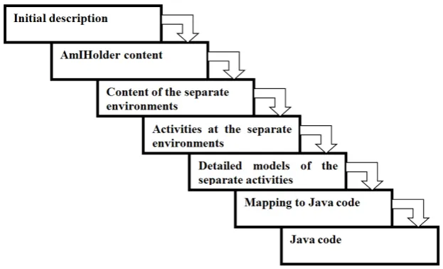
Every step provides the semantics (purpose or meaning) of the modelling stages and expresses the require- ments to the modelling concepts to be implemented in the concrete syntax, one form of which refers to the graphical notations. Horizontal part specifies a set of the possible models and concrete modelling elements, participating in the development of AmI environments, which finalised with state-chart diagrams representing code. The modelling elements are abstracted in the groups, providing basic entities, from which the elements are derived and; models are constructed. The idea of the horizontal methodology with the appropriate modelling stages are summarised in Figure 14. According to it flowchart the entire flow should contain the stages ex- pressed with the appropriate suggestion of concrete syntax:
Initial description in textual form. AmIHolder content.
Content of the separate environments.
Activities at the separate environments and detailed models of the separate environments as graphical models.
[image:18.595.128.482.351.519.2]Figure 17.Concrete syntax of AmI-Creator for coarse organization of the environments (the first, second and last row show the examples only).
Figure 18. Concrete syntax of AmI-Creator for realization of the performances at the different environments.
These suggestions express the requirements to the Domain-specific language-AmI-Creator, which should provide means of textual, graphical and Java programming representations of the particular stages of the devel- opment process. To support the idea of MDD for the development of AmI-E it should be supported by the ap- propriate software development tools. The requirements to the tools comprise their capabilities of expressing of all necessary notations specified in DSL.
6.1. How A-Methodology Works
[image:19.595.98.501.351.582.2]Figure19. Concrete syntax of the AmI-Creator DSL for depicting of more detailed performance at environ-ments.
6.1.1. First Way
The first way is dedicated to the cases when a developer approaches to a development without previous knowledge about a domain and/or a way of its creation. The current research demonstrates a use of such way through a consideration of AmI domain. Such case requires studying the domain through the available sources of information, e.g published documentation. Consideration and analysis of the information should be followed by an extraction of the meaningful elements with their succeeding abstractions in groups, which represent the domain concepts accompanied with their intercommunications. The intercommunications of the entities can be purposeful and lead to a performing of some processes. The groups with their intercommunications and pro- cesses are represented in ontologies of real world (see A-MDA level M0). The ontologies represent the domain semantics and provide a list of meaningful elements for initial modelling to be undertaken at A-MDA level M1.
The purpose of the activities at the level M1 is to investigate the modelling stages forming the entire modelling process finalised with models of code. The result of the investigation specifies the entire set of activities to be completed towards the final target of modelling code. Every stage of the modelling process has its own aim, which requires its own expression in some kind of formal representation.
Such multi-level representations refer to notations of multi-language dedicated to AmI domain with its focusing on the development of AmI environments. The multi-language should have two main notations: textual and graphical. They correspond to the development stages (see Figure 14).
Concluding this part the current research shows that the first way is dedicated to preparing a base for the horizontal part of the methodology, which is devoted to the development of Am-E and described as a second way of using the methodology and dedicated to the development of AmI environments.
6.1.2. Second Way
The second way of using the methodology (also refer to continuing of the First way) should be used during the development of a prospective AmI-E, when a domain is already learned, tools are specified and set of models are already identified and complete. The activities comprising the Second way refer to the horizontal part of A- methodology (corresponding toFigure 14) and comprises:
1) Identification of the entire structure of the AmIHolder. 2) Identification of the AmI environment content.
verification and testing. The validation was provided for ontology, the AmI-Creator’s semantics and syntaxes, existing languages and tools. Verification is provided for the proposed hypothesis. Testing is provided for the entire approach.
7.1. Validation
The validation of the AmI ontology was provided on three different examples from different domains compris- ing business, health and self-care-related applications, corresponding to Maria Scenario9, Virtual Hospital10 and Tea-making application [63]. The validation refers to a checking whether the every entity of AmI ontology presents at the considered example.
Such, for example the Patient case shows that AmI activities take part at Environments (Reception room, Examination room, Surgeon room and Recovery room), which comprise AmIHolder. Every Environment con- tains a set of the Devices capable of detecting a different environmental data or Context. The example of such device is a device capable of a detection of a specific signal (or a Context) from a patient’s tag. The Device is equipped with a data-detecting feature; the patient’s tag is equipped with signal-generating features. Such fea- tures ensure the interconnections, which facilitate a Network. A signal’s generating and its detection take Time. This validation showed the presence of all elements of AmI ontology: AmIHolder, Environment(s), Device(s), Context, Network(s) and Time. The result of the verification, summarized in the Table 3. It shows that all semantic concepts identified in AmI ontologies are found in all three examples, which proved that the obtained ontologies are valid properties of the AmI environments.
7.2. Verification
The verification of the considered existing languages and tools demonstrates that they cannot facilitate the de-velopment of AmI systems. This is because they cannot completely satisfy the requirements to building of AmI environments, narrowed to the certain number of notations and development steps. Such requirements refer to an ability of the tools to provide all notations necessary for building of the software application from AmI domain (Table 4). The table presents the comparisons of such tools as VP11-Visual-Paradigm (general purpose Software development tools) and MetaEdit+12 (dedicated to the development of domain-specific languages). Such tools would realize a use of the proposed language which can depict the steps of the development of AmI-E compris-ing nine stages (depicted in the Figure 15). They comprise:
1) Initial textual description of the functionalities of the entire system and at the separate environments(at stage one).
2) Depiction the entire AmIHolder and environments in an architectural notations (at the stage two see the con-crete syntax of AmI-Creator at Figure 20).
[image:21.595.116.482.612.676.2]3) Expression of the analysis at the stages 1 and 2 in the modeling concepts, which are the graphical depictions of the AmIHolder comprising the Environments and their order of the participation in the overall perfor-
Table 3.Verification of AmI ontology.
Application AmIHolder Environment Network Device Cotext Time
Maria Yes Yes Yes Yes Yes Yes
Patient Yes Yes Yes Yes Yes Yes
Tea Yes Yes Yes Yes Yes Yes
9
SCENARIOS FOR AMBIENT INTELLIGENCE IN 2010 final report at ftp://ftp.cordis.europa.eu/pub/ist/docs/istagscenarios2010.pdf 10link “Visit the Virtual Hospital” at http://content.dell.com/uk/en/healthcare/healthcare-solutions.aspx
11
http://www.visual-paradigm.com/product/vpuml/
Figure 20. AmIHolder of the Patient case.
Table 4.Comparison of VP and MetaEdit+.
VP MetaEdit+
Provide predefined graphical notations Allows creation of graphical notations
Does not provide coherent development of an application Does not provide coherent development of an application
Offers various diagrams meaning of which can be vague Offers some pre-developed examples with graphical notations
Does not allow depiction of time and activities in the same diagram No inbuilt examples showing time and activity representation
Generate Java code as code shells with Instantly generate XML code
Attributes and methods and XML Schema Requires a lot of efforts to develop code generation
Present separate diagrams only Requires a lot of efforts to develop code generation
Generate Java shell from Class diagram only Do not have means of the analysis of an application
Does not allow depiction of meta-concepts
(which means it is not possible to reuse the developed parts) Allows meta-concept; development profiles and reuse
mance (at the stage three see the concrete syntax of AmI-Creator at Figure 16).
4) Analysis of the activities at the separate environments (at the stage four see the concrete syntax of AmI- Creator at Figure 16).
5) Analysis of the kind of the devices and their placement at every environment (at stage five see the concrete syntax of AmI-Creator at Figure 17).
6) Analysis of the behavior of every environments (at stage six Figure 18).
7) Graphical representation of each performance allocated at the appropriate environment (at the stage seven see the concrete syntax of AmI-Creator at Figure 19).
8) Detailed representation of each performance (at the stage eight Figure 19).
9) Code representation (at the stage nine see the concrete syntax of AmI-Creator at page 14).
The Table 4 describes the features of VP and MetaEdit+, which are not fully satisfied the completion of the current task. The derived conclusion is based on the following speculations:
7.3. Validation of MetaEdit+ the DSL-Dedicated Tool
[image:22.595.126.514.86.295.2]in-showed that a development of such language introduces a problem and requires an additional training (time on which will oversee the time allocated on the entire research). It also would require a lot of programming expe-rience in writing a translator from graphic-based to a programming-based modeling (program-based implies a use of the conventional programming languages as Java, C++, C sharp).
7.4. Validation of Visual Paradigm-a General Software Development Tool
The overall UML at VP contains two types of diagrams: Structure (to depict statics in the modelling) and Beha-vior (to depict dynamics in the modeling). They comprise thirteen diagrams and eight sub-diagrams. The set of diagrams covers a very wide range of purposes for the development and at a first glance it looks like they possi-bly could solve the problem of modeling of AmI environments. The following text describes the results of the experiments with the existing tools. It shows how fully a use of UML can satisfy the requirements for the tools capable of holding all features necessary for the development of Ambient Intelligence environments.
The first step in the AmI-E development refers to the initial description of a prospective AmI-E. Visual Para-digm provides two types of the textual support, referring to the “textual analysis” and “report”. The VP intention of using the “textual analysis” is to identify the future modeling elements, e.g. class, actor, activity, actions, whereas “report” features refers to a generation of the report from developed models. The second kind of the textual support can only be generated and for this reason it is not suitable for the initial description.
The first type of the textual support cannot be adapted for producing the initial documents to be discussed with the customer as it does not provide the features of importing an image file (with picture of the environment) or drawing a content of the environment for the third stage of the development. The activity of “Producing a high level of a graphical model of an entire system” by modeling features of VP shows that UML provides sev-eral types of diagrams capable of depictions different features and comprises Class diagram, Component dia-gram, Package diadia-gram, Deployment diadia-gram, Object diadia-gram, Composite structure diagram.
The consideration of UML’s class diagram shows the problems with depicting activities. For example Class diagram is not capable of depicting a notion of time, which is important for the current research context. Other-wise it is capable of the depiction of a Device, Environments with the allocated performances, which should be completed at the AmI-E.
As UML Use case diagram refers to a behavior diagram the current research tried to adapt it for a depiction of statics along with system functionalities. The Use Case diagram shows that a Device (expressed in an Actor UML notation) is a communicating device capable of communication with other devices. The Use case diagram can depict the set of operations (or performances) and places of their allocation, but cannot show the exact se-quence of such; as well as cannot depict time when the operation is to take part.
The consideration of the other kinds of the diagrams comprising Component diagram, Package diagram, De- ployment diagram, Object diagram, Composite structure diagram, Interaction overview diagram demonstrates that these diagrams are not dedicated to such features and their adoption would bring the same complications as lack of precise sequence of the operations and time depiction. The following experiment involves the considera-tion of UML’s ability to cope with the tasks referring to the dynamic processes in the separate environments. For this purpose the current research considers the behavior diagrams: Use case, Activity, Interaction (Sequence, Communication, Interaction Overview, Timing) and State Machine diagrams.
Having considered the Use case diagram the research looks at the features of Activity diagram allowing a de-piction of an Environment, the set of the elements comprising the environment and the performance.
The vertical swim-line of the Activity diagram is capable of an incorporation of the features representing en-vironments. Despite activity diagram allows creation of an additional swim line dedicated to the depiction of time, the features of this diagram are not capable of the depiction of a precise point of time or length of time. The identification of the precise sequence of the operations courses a problem.
envi-The verification of the Language approach to the development of AmI environments showed that the number of the obtained notations is sufficient for the development of all stages and all notations which were met in the considered examples.
7.5. Testing
The proposed solution was tested on the developments of three different applications comprising: Tea-making application, Maria-scenario and Patient at the surgery. Because of too large sizes the demonstration of two first applications are not included in this paper. The third application is presented fully. It demonstrates an entire process of using of A-methodology’s horizontal part. The testing of the proposed solution comprises inspection of:
Whether the proposed set of steps of the Horizontal methodology is sufficient for the development of AmI-E. Whether the proposed AmI-Creator is capable of depicting the all necessary entities.
7.6. The Full Example of the “Patient” Application Is as Follow
1) The proposed solution is demonstrated through the Patient example based on the step-by-step sequence of performances. The future application refers as a process-based. The area of the application of the system refers to health care organizations. The analysis comprises: “The purpose of the system under the develop-ment is providing an electronic maintenance of a patient records’ assisting a person during his/her presence at a hospital. The treatment journey is starting at a patients’ consultancy room and finishing at a patients’ discharging room. The treatment is taking place at a sequence of different environments with different functionalities. All of these environments are supplied with a device containing patients’ records. Complet-ing the predefined functionalities requires a sequence of specified environments (patient reception room with nurse taking initial data from patient; patient examination room with doctor-consultant examining the patient health condition; surgery room with doctor providing operation; after surgery patient’s room for pa-tient recovery (visited by doctor-consultant and nurse)). The listed environments are supplied with equip-ment supported with sensing devices capable of detecting tags and voice commands. Such detections are based on hands free communications through wireless network. The communication requires time to com-plete a set of tasks allocated to the appropriate environments.”
2) The area of the application of such system refers to health care organizations.
fied information is uploaded onto the tag.
Examination room: Room tag detection device detects the patient ID through the tag, identify the patient and displays the data on the device screen.
Surgeon (or operation theatre): Room tag detection device detects the patient ID through the tag, identify the patient, notifies surgeon about the patient health conditions and start recording the operation at the specified time.
Recovery room: Room tag detection device detects the patient ID through the tag, process the data, finds and displays the data about the patient.
The set of the environments at AmI Holder, organized in the order of their participation in the overall perfor-mance depicted in Figure 21.
[image:25.595.126.477.302.708.2]7) The detailed description of the sub-performances in Figure 22 comprises:
Figure 21.The environments at AmIHolder.
environments.
9) Division of the overall performance into the separate performances is summarized in the Table 6.
10)The analysis of the sequence of the performances showed that they take part one after the other, which lead to conclusion that such AmI-E is a performance oriented.
11)The detail sequence of the sub-performances with the appropriate environments are as follow:
a) At the reception: The passive tag is placed at the allocated area; on the request communication it sends the responding signal, which makes the controlling device start uploading patient information if tag is empty Figure 23.
b) At the examination room: the patient (with the tag) is placed at the allocated area; the controlling device sends the request to communication; the tag responds by the signal; the controlling device (ConDev) performs the appropriate activities Figure 24.
c) At the operation theatre: the ConDev sends the request signal; the tag responds; the ConDev displays the information on a screen and stars recording the operation Figure 25.
[image:26.595.92.528.457.557.2]d) At the recovery room: the ConDev sends the request signal; the tag responds; the ConDev displays the information on a screenFigure 26.
Table 5. The summary of the devices required for the Patient AmI-E.
Environment Performance Devices
Patient reception room
After the tag recognition the reception control device uploads a patients ID and
data on the patient tag
Patient wrist tag refers to a passive tag (equipped with read-write RFID (Radio Frequency
Identification) or SAW (Surface Acoustic Wave))
Doctor-consultant room, Operation theatre, patient recovery room
On the patient’s taking an appropriate position the room control system Identifies the patient and display data
on the appropriate screens
Patient wrists tags (e.g. read-write RFID (Radio Frequency Identification)) or SAW (Surface Acoustic Wave). ConDev device
[image:26.595.93.533.501.717.2]computer is equipped with interrogator.
Table 6. Division of the overall performance into the separate performances.
Performance Performance description
Uploading ID and data about patient on his tag
On arriving to the hospital a patient is given a wrist electronic tag. When patient is registered, the information about him is stored on the server, holding database records of all patients. This is done wirelessly through the communication distance up to
10 meters: When patient is placed at the appropriate position (one at the time) the room controlling device detects the passive tag and sends the appropriate data on it
Identifying patient at the doctor-consultant room
When patient entered in the consultant’s room, his passive tag is detected by client computer’s interrogator; the room controlling device displays the information about the patient on a screen
Detecting patient at the operation theatre
When patient is in the operation theatre his tag is identified by the reader of the controlling device and displays the appropriate patient’s record and start recording the operation
Detecting Patient at the recovery room
Figure 23. Analysis of the performance at the reception.
[image:27.595.130.473.403.575.2]Figure 24. Analysis of the performance at the examination room.
Figure 25.Analysis of the performance at the operation theatre.
12)The modeling of the separate performances for example as modeling of the performances at the appropriate environments: Reception room (top right counter), Examination room (top left corner), Operation theatre (bottom right corner), Recovery room (bottom left corner); and obtaining a pattern is shown as in Figure 27. 13)More detailed analysis of the performances is shown in the Figure 28. They are the same for all of the
en-vironments. As it can be seen from the previous part both of the devices perform the following operations: “detect”, “process” and “respond”. In respect to this particular case the server side refers to Patient tagging device (or tag), whereas client part refers to the communication device. They perform the same operations, but the exact contents of the appropriate inference engine and network communications would depend on the discussion with the appropriate specialists about creating a knowledge base system (for an output infe-rence) and a network adviser.
Figure 26.Analysis of the performance at the recovery room.
Figure 27.Realization of the performances at the different environments through the modeling.
[image:28.595.104.497.277.646.2]Figure 28. More detailed analysis of the performance at the reception.
erties are presented as classes because they have their own properties. The classes are shown as set of array data type because the instances of these classes can correspond to the several properties with different values. Such for example class Device can contain Patient Tag and Connecting Device. In this case the Device class will have two instances, what would be indicated as index of 2: Device [2].
8. Conclusions and Further Work
This part provides a summary of the completed research.
Figure 29.Mapping into Java classes.
Figure 30. Concrete syntax of the AmI-Creator DSL for depicting of server client communications.
[image:31.595.128.470.335.709.2]This section provides the demonstration of the advantages of the proposed approach through a comparative analysis of the two latest approaches published after the starting date of the current research.
The latest literature survey showed some of the AmI-relevant publications, dedicated to other areas of AmI e.g. towns and wider geographical areas, beach and dance floor. They do not produce DSL or AmI development methodologies. Some of them show stages such as identification of the purpose or development hardware and software (without giving the detailed explanations).
The first example proposes an approach to building a prototype. Alternative to De Ruyter’s approach [55] the current research proposes a different insight into the problem of the development of AmI. It comprises planning and analyzing of the future system before building actual prototypes or full size model of the future environment. In the author’s opinion such approach is based on modeling (showing planning ahead with identifying an ini-tial purpose), choosing the appropriate devices (based on their ability to detect the context at the specified area), specifying the most appropriate placement in the environments; and providing coding—is a more ad-vantageous way in the sense of saving efforts in the development of such systems. Such an approach also speeds up the coding process and reduces the end code errors. Checking a visual code model is always easier than checking a numerous lines of the actual code. The visualization of the development process through the symbolical representation, code visualization (through its depiction in graphical notations) can be discussed with the appropriate non-programmer specialist (as network or device engineer). Such discussion seeks for an immediate feedback.
The second example [64] also refers to the practice of a full size prototyping of AmI environments. It points to the importance of a system’s deployment. It also points to a focus on small innovations on specific parts of home automation systems, which don’t consider integration and deployment issues to present practical designs. The Zamora-Izquierdo’s article offers “direct adaptation to specific cases using standard domotic technologies, for managing in-house devices. It also proposes an IP-based network for connecting the main home automation module with other platform elements”. It refers to “A remote security system has been developed, and managing tasks are enabled via in-home control panels and an advanced 3D application for local and remote homeowner access.” This was deployed on the prototype house testing domotic services. They point out the extension to e- health, elderly adaptation, green house automation.
Differently from this approach the current research does not specify a particular application area.
In contrast to both of the described approaches the current research pays particular attention to the provided feedback. Such feedback can help to speed up the process of the AmI-E development and avoid an unnecessary testing before planning and analyzing the prospective AmI-Es. Therefore, the Horizontal methodology defines the step-by-step process of the actual development of the prospective AmI-Es. Along with providing the means of intercommunication it provides the sequence of models, finalized by the models of the working code. Such modeling process leads to modeling of the code. Such approach can alleviate the process of coding and help to avoid coding errors. It also can help to speed up the entire process for the development of AmI-E.
con-The current research can be considered as state-of-art in the chosen field, which is dedicated to serving needs of the third wave of computing (AmI as Ubicomp) by means of fourth generation of software development (show-ing a way to code generation through a realization of mapp(show-ing).
The reason for a considering the presented work as the state-of-art is because it presents the easiest way of creating of Ambient Intelligence environment from scratch. The benefits of using such approach cover leaving coding to the latest stage of the development. This approach helps to reduce considerably (or completely avoid) error in the final code. Providing these, the presented work helps to reduce labor and time consumption. It also allows producing the AmI environments in easy and error-reducing steps.
Furthermore, the research provides the direction for the further development in AmI domain by extension of its applicability to the other frameworks (for example for concurrency). The current research presents a process- oriented framework. Moreover, the current research assumes the applicability (or adaptation) of the methodolo-gy to other systems with a complex organization. Besides, the current research based its own realization of the subject on the consideration of the existing SE approaches and AmI-dedicated experiences (shown appropriately in Figure 32).
8.4. Further Directions
[image:33.595.101.497.449.681.2]The realizations and completion of the identified subject depicted in Figure 32 as “Existing information from world knowledge” was provided through the research of an AmI development approach, which also referred to a software development approach (approach to development of DSL through initial identification of the language semantics and A-methodology comprising Vertical and Horizontal parts)—referred to the Box named “Target-ing knowledge”. The new areas for the further development and obtain“Target-ing a new knowledge (depicted as “New areas for the research based on the obtained knowledge”) arise from the “Targeting knowledge” of the current
2007, 496-501.
[3] Vales-Alonso, J., López-Matencio, P., Gonzalez-Castaño, F.J., et al. (2010) Ambient Intelligence Systems for Persona- lized Sport Training. Sensors, 10, 2359-2385. http://dx.doi.org/10.3390/s100302359
[4] Bravo, J., Hervás, R., Casero, G., Peña, R., Vergara, M., Nava, S.W., Chavira, G. and Villarreal, V. (2008) Enabling NFC Technology to Public Services. 1st International Ambient Intelligence Forum 2008, Hradec Králové, 15-16 Oc-tober 2008, 58-65.
[5] Garcia, O., Tapia, D.I., Rodríguez, S. and Corchado, J.M. (2010) Ambient Intelligence Application Scenario for Col- laborative E-Learning. 23rd International Conference on Industrial, Engineering and Other Applications of Applied Intelligent Systems, Cordoba, 1-4 June 2010, 407-416.
[6] Norgall, T. (2009) Fit and Independent in the Aging Population Using Technology. From Concept to Reality. Bundes-
gesundheitsblatt-Gesundheitsforschung-Gesundheitsschutz, 52, 297-305. http://dx.doi.org/10.1007/s00103-009-0789-5
[7] Streitz, N. (2007) Designing for People in Ambient Intelligence Environments. International Conference on Ambient Intelligence Developments, Ami.d 2007, Springer, Berlin, 47-54.
[8] Remagnino, P., Foresti, G.L. and Ellis, T. (2005) Ambient Intelligence: A Novel Paradigm. Springer, Berlin.
http://dx.doi.org/10.1007/b100343
[9] Feng, L., Apers, P.M.G. and Jonker, W. (2004) Towards Context-Aware Data Management for Ambient Intelligence. 15th International Conference on Database and Expert Systems Applications, 3180, 422-431.
[10] Aarts, E. (2003) 365 Days Ambient Intelligence in Homelab Ambient Intelligence: Building the Vision. Royal Philips Electronics.
[11] Weiser, M. and Brown, J.S. (1996) The Coming Age of Calm Technology.
http://www.johnseelybrown.com/calmtech.pdf
[12] Ali, R., Abdel-Naby, S., Maña, A., Muñoz, A. and Giorgini, P. (2008) Agent Oriented Ami Engineering. Developing Ambient Intelligence, Springer, Paris, 166-179.
[13] Stuikys, V. and Damasevieius, R. (2007) Variability-Oriented Embedded Component Design for Ambient Intelligence.
Information Technology and Control, 36, 16-29.
[14] Augusto, J. (2010) Past, Present and Future of Ambient Intelligence and Smart Environments. In: Agents and Artificial Intelligence, Vol. 6, Springer, Berlin, 3-15.
[15] Eisenhauer, M., et al. (2009) Ambient Healthcare Systems Using the Hydra Embedded Middleware for Implementing an Ambient Disease Management System. 2nd International Conference on Health Informatics (Healthinf 2009), Porto, 14-17 January 2009, 82-89.
[16] Abascal, J., Bonail, B., Gardeazabal, L., Lafuente, A. and Salvador, Z. (2009) Managing Intelligent Services for People with Disabilities and Elderly People. 5th International Conference on Universal Access in Human-Computer Interac-tion Held at the HCI InternaInterac-tional 2009, San Diego, 19-24 July 2009, 623-630.
[17] Carneiro, D., Costa, R., Novais, P., Neves, J., Machado, J. and Neves, J. (2008) Simulating and Monitoring Ambient Assisted Living. European Simulation and Modelling Conference, Le Havre, 27-29 October 2008, 175-182
[18] De Paz, J.F., Rodriguez, S., Sánchez, J.M., de Luis, A. and Corchado, J.M. (2007) Context Aware Hybrid Agents on Automated Dynamic Environments. 2nd International Workshop on Hybrid Artificial IntelligenceSystems, Salamanca, 12-13 November 2007, 25-32.