Space Time Block Code Analysis for MIMO-OFDM
System
Vinay Kumar
Research Scholar(P.hD) St.Peter’s University
Cheenai(TN)
C.Ram. Singla
Professor & Dean (R&D) Dronacharya college of Engg.
(Gurgaon-HR)
Chirag
Asst.Prof(ECE) SITM-Sonepat(HR)
ABSTRACT
The growth in high data rate mobile data transmission in recent years is due to the tremendous achievements in Digital Communication especially Digital Modulation Techniques starting from Second Generation system (2G) in early 80’s to today 4G (LTE – Advanced). To achieve the goal towards Shannon’s Channel Capacity, a no. of modulation techniques are developed during these years. With the tremendous growth in the Very Large Scale Integrated Circuits (VLSI), a no. of digital modulation techniques is easier to implement in convenient manner. Orthogonal Frequency Division Multiplexing (OFDM), one of the latest techniques became feasible and economical due to the high processing speed. OFDM in combination with other techniques like Space Time Block Code (STBC)Phase shift key (PSK) and Quadrature Amplitude Modulation (QAM) give better performances in case of Multi- input Multi-output System (MIMO).
This paper presents (STBC) technique for multiple transmission antennae (OFDM) system. Generally in Multi- input Multi- output (MIMO) system code selection across the space and time is difficult to get minimum Bit Error (BER) to achieve maximum output. In adaptive White Gaussian (AWGN) fading channels, STBC is best breakthrough to reduce the BER and obtain maximum output. Like AWGN fading channel the analysis is done for OFDM system using STBC at transmitter end. Various modulation techniques like Binary Phase Shift Key (BPSK) and Quadrature Amplitude Modulation are implemented using mentioned techniques. The Bit Error Rate (BER) versus different Signal to Noise (SNR) ratio are studies for above modulation techniques.
Keywords
STBC, MIMO, OFDM SYSTEM, AWGN, BPSK, QAM and BER
1.
INTRODUCTION
MIMO is the current technology that is supported internationally by the Wireless Systems. LTE – Advanced support more sophisticated MIMO techniques, which enable several antennas to send and receive data. One use of MIMO, called multiplexing separates transmissions into many parallel streams, increasing data rates in proportion to the no. of antennas used.
In recent years, to the development of integrated circuits to surface mounting devices and processors, computational power is believed to grow exponentially with time [1,3]. This has enabled the feasibility of implementing MIMO system and associated signal processing algorithms.
Fig 1. below shows the LTE – Advanced MIMO
both Transmitter (TX) and receiver (RX) which increases upload and download speed.
Fig. 1 MIMO Communication System
MIMO Technology offers a no. of advantages in wireless communication system viz:
1. It offers significant increase in data throughouput and link range without additional bandwidth or transmit power. As in LTE – Advanced it employs carrier aggregation operation to increase throughout up to 20 MHz
2. It provides more spectral efficiency i.e large no. of bits per second per hertz of frequency.
3. It provides high reliability and reduces the fading in channels thus increasing diversity.
[image:1.595.347.506.262.450.2]2.
CODING TECHNIQUE
2.1
Space Time Coding (STC)
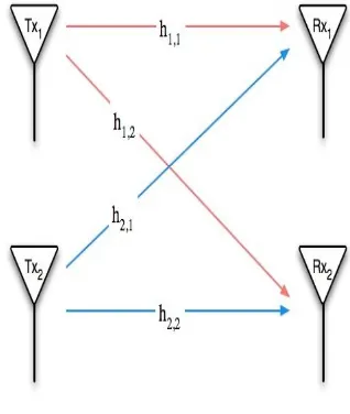
Various coding techniques are used in wireless communication system to improve the reliability, data throughout, Error control and to decrease the BER (Bit Error Rate).Space time coding(STC) is a technique of Space Division Multiplexing (SDM), where space and time diversity are implemented by using multiple antennas to improve the reliability of data transmission.
The concept of space time coding has got tremendous attention in wireless systems in recent years due to the diversity techniques implemented using smart antennas. STC is more effective than traditional diversity techniques like Rake Receiver etc. due to the use of coding and signal processing at both sides of TX and RX. [2,4]. Diversity and multiplexing are two major operation in STC.
A trade off should be required between above factors to get the maximum performance.
STC’s works on the principle of transmitting multiple, redundant data to receiver such that some of the copies of data will follow the physical path between transmitted and reception in a good faith to allow reliable decoding (9).
Some of the features of STC are;
1. It provides improved link reliability.
2. Using resource allocation properly, it increases system capacity.
3. A best possible tradeoff is provided between date rate, constellation size, diversity advantages and trellis complexity.
Most commonly used STC fall under following categories –
1. Space Time Trellis Codes (STCs)
2. Space Time Turbo Codes (STTuCs)
3. Space Time Black Codes(STBCs)
2.2
Orthogonal Frequency Division
Multiplexing (OFDM)
OFDM is based on the idea of frequency – division multiplexing (FDM), but the multiplexed data streams are all parts of a single original stream. The bit stream is split into several parallel data stream, each transferred over its own subcarrier using some conventional digital modulation technique. The modulated subcarriers are summed to form an OFDM signal.
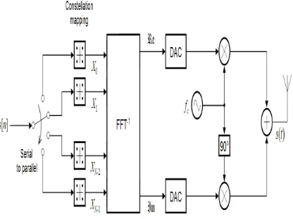
In short an OFDM system is multicarrier system which allows the transmission of data streams on many closely spaced, orthogonal subcarriers using parallel processing technique. This dividing and recombining helps with handling channel impairments. OFDM is considered to be as a modulation technique rather than a multiplex technique, since it transfers one bit stream over one communication channel using one sequence of so called OFDM Symbols. Conventional OFDM uses the Inverse Fast Fourier Transforms (IFET) to multiplex the signals together and decode signals at receiver end. Inter symbol interference (ISI) is minimized due to addition of cyclic prefixes (CP) before transmission[11].
Although OFDM is being popularly used in telecommunication but it has gained potential response in next
generation wireless era and MIMO , due to high data rate of greater then 1 Mbps at a speed of 25km/h.
[image:2.595.325.533.172.328.2]OFDM can be extended to multi user channel access methods in the orthogonal frequency division multiple access(OFDM) and multicarrier code division multiple access (MC – CDMA) schemes, thus allowing several users to share the same physical media by fixing different sub- carriers or spreading codes to different users.
Fig 2: Idealized OFDM system model(Tx) for AWGN channel
2.3
QUADRATURE AMPLITUDE
MODULATION TECHNIQUE (QAM)
One of the most used modulation technique in digital data radio communication and data communication application is QAM due to its widespread use in current and emerging technology. QAM is implemented in variety of communication protocols. Current protocols such as 802.11b wireless Ethernet (Wi-Fi) and digital video broadcast (DVB), for example both utilizes 64 – QAM modulation.In QAM modulation digital information is send periodically by adjusting the amplitude and phase of sine carrier wave. A digital stream is represented by each combination of phase and amplitude also called a symbol. Simplest way to implement QAM with the hardware is to generate and combine two sine waves that are out of phase with each other. Amplitude and phase of resultant signal can be affected by adjusting only the amplitude of either signal.
The two carrier waves represented in –phase (I) and Quadrature phase (Q) are represented individually as
I=V Cos θ---(1) & Q=V Cos (θ+90o) ---(2) = V Sin θ
From above equations and using identities we can write as equation 1 as
Fig 3. Hardware Used to Generate the IF Signal
It is clear that, QAM in values sending information by periodically adjusting the phase and amplitude of a sine wave.
Four QAM uses four combinations of phase and amplitude. Moreover each combination is assigned a 2 –bit digital pattern.
For Example it is to generate the bit stream (0,1,0,1,0,1). Because each symbol has a unique 2 bit digital pattern, grouped in two’s to map the corresponding symbols. In our example, the original stream is grouped as (01,01,01)
In the fig, 4 QAM consists of four unique combinations of phase and amplitude. These combinations of phase and amplitude are represented as the white dots on the constellation plot.
The red lines represent the phase and amplitude transmission from one symbol to another.
[image:3.595.64.269.70.207.2]The plot shows the digital pattern represented by each symbol.
Fig 4. 4-QAM Symbol Map
As explained above 2 bits per symbols can be represented using 4-QAM modulation, it is possible to send data even at higher rates by increasing the number of symbols in the symbol map. By convention the number of symbols in a symbol map is called the symbol map “M” and is considered
as “M – ary” modulation scheme.
In short, 4 QAM has an M-ary of four and 256 – QAM has an M – ary of 256.Conventionally there is a logarithmic relationship to ‘M-ary’ to define one of bits symbol.
For Example 4 QAM is defined by relation log2 (M) that is Log2(4) = 2bits per symbol.
Similarly 256 –QAM can be represented by 8 bit digital pattern per symbol.
Because the M-ary of a QAM modulation scheme affects the no. of bits / symbol, the M-ary has significant effect on the
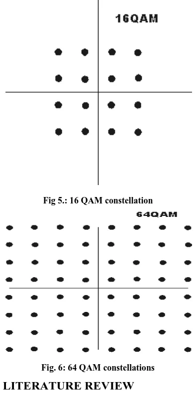
[image:3.595.329.526.131.526.2]Fig 5 & 6 below shows the the common QAM schemes as 16 QAM, 32QAM and 64QAM, with different positions for the states within these forms of QAM. As the order of modulation increases, so does the no. of points on constellation QAM diagrams.
Fig 5.: 16 QAM constellation
Fig. 6: 64 QAM constellations
3.
LITERATURE REVIEW
Jungho Myung et. al.[7] presented a symbol error rate (SER) study for dual hop relayy by networks employing STBC from co- ordinate interleaved orthogonal design (STBC – C10D). Here the author provides the union upper and lower bounds on the average SER by closed hop formula for the corresponding symbol pair wise error rate (SPER)
Sandipan Kundu et. al. [8] presents a maximum likelihood(ML) decoder with with the lowest computational complexity known to date for full diversity arbitrary size Quasi – orthogonal Space Time Block Codes (QO – STBC’s) with symbol from square or rectangular QAM constellations.
[image:3.595.55.275.425.574.2]Jae – Shin Han et.al[10] presents for multimedia broadcasting system multiinput multioutput orthogonal frequency division multiplexing (MIMO- OFDM) system with dual – polarized division multiplexing (PDM) and diversity.
Author analyses the output signal – to- interference pluse-noise ratio (SINR) of such MIMO detections in terms of cross polarization detection (XPD) effect. It is observed that output SINR of MIMO – 2F detection increases as the absolute XPD increases.The author concluded that as the absolute value of XPD increases, the polarized MIMO – OFDM system provides a lower symbol error rate then unipolarized MIMO – OFDM system.
4.
RESULTS AND CONCLUSIONS
16PSK, 16QAM and 64QAM ie three MIMO STBC OFDM wireless communication systems are designed and simulated by MATLABR 2013a with following input parameters as
1. numbr_bits = 16*10^3;
2. numbr_symbols = 4;
3. SNR = 8:2:22;
4. FFT_level = 4;
5. Constellation = 16;
6. cyclic_prefix = 2;
[image:4.595.316.535.65.516.2]16 PSK MIMO-STBC-OFDM SYSTEM
Fig. 7 BER vs. SNR for 16 PSK
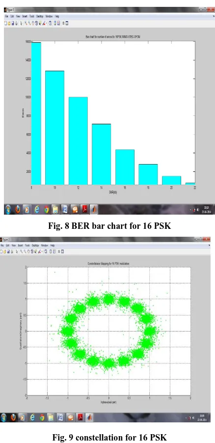
Fig. 8 BER bar chart for 16 PSK
Fig. 9 constellation for 16 PSK
[image:4.595.52.270.372.603.2]16-QAM MIMO-STBC-OFDM SYSTEM
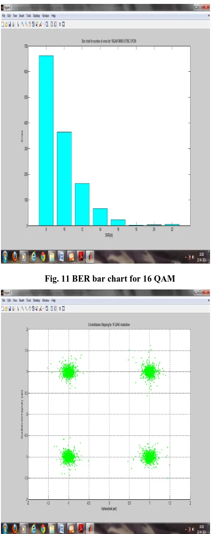
[image:4.595.313.531.539.748.2]Fig. 11 BER bar chart for 16 QAM
Fig. 12 Constellation for 16 QAM
64-QAM MIMO-STBC-OFDM SYSTEM
Fig. 13 BER vs. SNR for 64 QAM
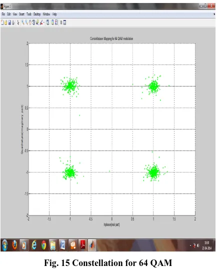
[image:5.595.315.533.73.358.2]Fig. 15 Constellation for 64 QAM
Various plotted graphs represent the following observation listed as
Table 1: BER & Errors at Input SNR
Features
Techniques
16 PSK 16QAM 64 QAM
BER at input SNR 8 dB
0.23783 dB 0.20821 dB 0.01001 dB
BER at input SNR 22 dB
0.0103 dB 0.2013 dB 0.0001 dB
Errors at input SNR 8 dB
15792 13989 792
Errors at input SNR 22 dB
782 12792 01
From above data, it is clear that
1. BER at Input SNR decreases with the increase of Input SNR in dB.
2. Similarly errors also significantly reduces except in case of 16QAM technique, wherein errors are not improved significantly with the increase in input SNR.
5.
CONCLUSION
It is clear from the above that with the increase in symbols i.e with higher techniques, there is an improvement over the BER and errors at various Input SNR, 64 QAM has least BER and error followed by 16QAM and 16PSK techniques. There is remarkable improvement near 0 at BER and 1in the error in case of 64QAM techniques. Thus we can generalise that 256 QAM or more will give nearly or almost 0 BER and errors at INPUT SNR at 8 AND 22dB. Thus used in most of the wireless communication protocols.
6.
REFERENCES
[1] Philippe Ciblat, Philippe Loubaton, Member, IEEE, Erchin Serpedin, and Georgios B. Giannakis, “Asymptotic Analysis of Blind Cyclic Correlation-Based Symbol-Rate Estimators” IEEE TRANSACTIONS ON INFORMATION THEORY, VOL. 48, NO. 7, JULY 2002.
[2] Lei Wang, Member, IEEE, and Naresh R. Shanbhag, Senior Member, IEEE, “Low-Power MIMO Signal Processing”, IEEE TRANSACTIONS ON VERY LARGE SCALE INTEGRATION (VLSI) SYSTEMS, VOL. 11, NO. 3, JUNE 2003
[3] Chengshan Xiao, Senior Member, IEEE, Jingxian Wu, Sang-Yick Leong, Yahong Rosa Zheng, and Khaled Ben Letaief, Fellow, IEEE, “A Discrete-Time Model for Triply Selective MIMO Rayleigh Fading Channels”
IEEE TRANSACTIONS ON WIRELESS
COMMUNICATIONS, VOL. 3, NO. 5, SEPTEMBER 2004.
[4] Antonis Phasouliotis and Daniel K.C. So, “Performance Analysis and Comparison of Downlink MIMO MC-CDMA and MIMO OFDMA Systems” IEEE 2009.
[5] Marco Chiani, Senior Member, IEEE, Moe Z. Win, Fellow, IEEE, and Hyundong Shin, Member, IEEE, “MIMO Networks: The Effects of Interference” IEEE TRANSACTIONS ON INFORMATION THEORY, VOL. 56, NO. 1, JANUARY 2010.
[6] Lingjia Liu, Runhua Chen, Stefan Geirhofer, Krishna Sayana, Zhihua Shi, Yongxing Zhou, “Downlink MIMO in LTE-Advanced:SU-MIMO vs. MU-MIMO” IEEE Communications Magazine • February 2012.
[7] Jungho Myung, Student Member, IEEE, Hoojin Lee, Member, IEEE, and Joonhyuk Kang, Member, IEEE, “Performance Analysis of a Dual-Hop Relay With STBC-CIOD over Rayleigh Fading Channels” IEEE TRANSACTIONS ON VEHICULAR TECHNOLOGY, VOL. 62, NO. 1, JANUARY 2013.
[8] Sandipan Kundu, Weifeng Su, Member, IEEE, Dimitris A. Pados, Member, IEEE, and Michael J. Medley, Senior Member, IEEE, “Fastest-Known Maximum-Likelihood Decoding of Quasi-Orthogonal STBCs with QAM Signals”, IEEE WIRELESS COMMUNICATIONS LETTERS, VOL. 2, NO. 1, FEBRUARY 2013
[9] Jiayi Zhang, Student Member, IEEE, Michail Matthaiou, Member, IEEE,George K. Karagiannidis, Senior Member, IEEE, Haibo Wang, and Zhenhui Tan, Member, IEEE ,” Gallager’s Exponent Analysis of STBC MIMO Systems over η-μ and κ-μ Fading Channels” IEEE TRANSACTIONS ON COMMUNICATIONS, VOL. 61, NO. 3, MARCH 2013
[10] Jae-Shin Han, Jong-Seob Baek, Member, IEEE, and Jong-Soo Seo, Senior Member, IEEE ,” MIMO-OFDM Transceivers With Dual-Polarized Division Multiplexing and Diversity for Multimedia Broadcasting Services” ,IEEE TRANSACTIONS ON BROADCASTING, VOL. 59, NO. 1, MARCH 2013
[image:6.595.48.280.383.549.2]7 Annex-1
PROPOSED METHODOLOGY
1. Transmission channel design with AWGN depending upon no of bits and no of subcarriers.
1. Receiver design with reception of data with removal of all additional guard and pixel bits
1. Reconstruction of objects for demodulation using various methods based upon no of constellation and type of input data.
1. Calculate no of errors and BER
Plotting of data for
1. BER at each input SNR value.
2. BER bar chart for various techniques.
3. Constellation diagram Variable Declaration
1. No of Bits
2. No. of Subcarriers
3. Levels of Fourier Fast Transfer(FET)
4. No. Of Constellations
5. No of Cyclic Prefix
6. Input SNR
1. Generation of Binary Data
2. Construction of object to modulate binary data using QAM & PSK
1. Modulation of data
2. Serial to Parallel Conversion.
1. Grouping of 8 bit Size.
2. Division of grouped bits into size of 4.
1. X1,X2 Matrix Formation
2. Calculate complex conjugate to both matrices to get orthogonal data bits.
1. OFDM transmitter design based on FET no. Of cyclic prefix and no of bits.
Plotting of data for
1. BER at each input SNR value.
2. BER bar chart for various techniques.
3. Constellation diagram