A Novel Technique of Image Mosaicing based on
Discrete Wavelet Transform and its Performance
Evaluation
Ravi Bhushan
Department of Electronics and Communication Engineering
Dr B R Ambedkar National Institute of Technology Jalandhar (Punjab)-144011, India
Ramesh Kumar Sunkaria
Department of Electronics and Communication Engineering
Dr B R Ambedkar National Institute of Technology Jalandhar (Punjab)-144011, India
ABSTRACT
Limitation of camera or other imaging sensor regarding the area coverage in a single shot at a fixed resolution has coined the term Image mosaicing. It is an application of image registration which aligns images taken in different camera coordinate system (i.e. different orientation of camera). In this paper, a new technique of image mosaicing has been proposed in which Discrete-wavelet Transform(DWT) based feature detector and scale-invariant feature transform(SIFT) based feature descriptor has been used which makes this technique robust to image zooming, image rotation, affine distortion and illumination change due to varying light condition during image acquisition. Result shows the improved performance with respect to number of feature points detected and computation time. Also, quantitative evaluation parameter like structural similarity index (SSIM), normalized absolute error (NAE), etc. proves the better performance of this technique compared to other techniques till date.
Keywords-
Image registration; DWT; SIFT; NAE; SSIM;1.
INTRODUCTION
The reasons which coined the term image mosaicing are as follows: Firstly, image acquisition devices have constraint on capturing area at some resolution of image for a single instance of opening of shutter present in the device. One way to remove this constraint while capturing large image is to take images in smaller segments maintaining sufficient overlapping between them and using image processing technique, captured segmented image can be stitched together to make it larger one. Secondly, sometimes there is a requirement of an image at higher resolution with the lower resolution cameras then, we break the image area in to smaller areas so that smaller areas can becaptured at best resolution of the device and image mosaicing technique can be used to get the complete image. This type of requirement specially arises in case of biomedical images [1]. Along with this, Image mosaicing has application in satellite imaging system [2] and 2-dimensional realization of a 3-dimensional object by revolving the camera around the object and takingpicturesat regular interval. The term Image mosaicing, image stitching and panorama reconstruction are used interchangeably in the literature. Panorama reconstruction is an application of image registration technique in which two or more sufficiently overlapped images can be stitched together by understanding the geometric alignment of images with respect to a fixed camera coordinate system. In mathematical terms, it can be defined as the union of images treating image pixel location and corresponding intensity value as an element of set [3].
Now days, mosaicing facilities are also incorporated with some cameras available in the market. Also, there are plenty of softwares available on the internet like [4], etc.
There are mainly two methods for Image mosaicing as discussed in research Literature: Direct and Feature based. Direct method [5] uses intensity difference between pixels in the overlapping region as the parameter to calculate the accuracy of the algorithm. Based on intensity difference, transformation matrix is calculated iteratively. So, these methods give accurate registration but, they are not robust to image scaling, illumination change and noise present in an image. Compared to feature based method, it requires a good initial guess to achieve transformation matrix which is a major drawback of this method. Feature based method first identifies features (point, line, blobs, etc.) in every input image and establishes correspondence between these features based on some parameter. While comparing this method to direct method, it is robust to Illumination change, image scaling, noise, affine transformation and orientation of the image. It takes care of locality around detected features to describe that feature and is called as feature descriptor. If matching between images is needed, feature descriptor can be used. There are numbers of research literature [6, 7, 8] on feature based method showing the importance of these techniques. In this paper, point has been treated as feature. Flow chart for panorama reconstruction algorithm is shown in Figure 1.
[image:1.595.322.534.532.691.2]
Figure 1: Flow chart of panoramic view reconstruction
from an image most of the time. Any technique used for detection of feature point should be repeatable i.e. same feature points should be detected in every simulation of the algorithm. There are many techniques available in the literature for feature point detection such as Harris corner detector [9], SUSAN operator [10], SIFT [11], etc. Harris corner detection, which is mostly used feature detection technique in the research literature, is invariant to image rotation and illumination change (to lesser extent) but, it is not robust to image scaling. If this technique is used as feature detector for mosaicing purpose, there is a need to find correlation matrix between images around feature-points to establish correspondence between these features for calculation of transform matrix in panorama reconstruction but, the correlation operation is not invariant to rotation. So, image mosaicing based on this technique fails if there is any scale and orientation change among input images. Also, correlation matrix is calculated between input images within a fixed window around every feature point. This creates major problem in the case of affine transformation on the input images. Despite these problems, authors in their literature [12] are still using this technique when robustness of all these variation is not required. Authors in paper [11] defined SIFT which is a combination of both feature detector and descriptor. This technique is robust to all the parameter variation discussed above. This technique works well even if illumination changes and affine transformation occurs while taking input images. But this technique provides large number of detected feature-point which further increases computation time of the high level image processing algorithm. Literature shows that for an image of size 512x512, SIFT detector provides nearly 1000 feature points.
In this paper, a novel technique of image mosaicing based on discrete-wavelet transform as feature detector has been proposed which gives less number of interest points compared to SIFT detector which further reduces the computation time required for image mosaicing. SIFT descriptor has been used as feature descriptor to consider the locality around detected feature points. Based on the correspondence established by taking euclidean distance between feature descriptor vector of each pair as parameter, transform matrix is calculated so that all the input images can be brought back into the same camera coordinate system. Now, apply the transform matrix on the appropriate image and stitch the image but, stitched image may not be natural looking if there is illumination change between the input images while capturing image. To get smooth transition on boundary of the stitched image, good blending technique is required.
2. METHODOLOGY
2.1 Feature point Detection
It is the primary step which is almost involved with all the high level image processing applications. Feature detection through wavelet needs a wavelet which will be compactly supported and will have linear phase. Orthogonal wavelet satisfies these properties. Two wavelet functions
ψ(t)
andˆψ(t)
are said to be orthogonal if equation (1) satisfies.ˆ
< ψ(t), ψ(t - k) > = δ(k)
(1) Where k is the delay factor. Techniques are available to find features based on discrete wavelet transform [13]. In this paper, a novel feature detection (preliminary steps for Image mosaicing) technique based on combination of both discrete wavelet transform and modified-Harris corner detection
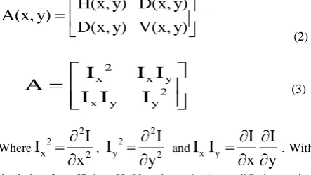
algorithm has been proposed. In this technique, Image and its scaled version has been passed through 2-dimensional bi-orthogonal spline type wavelet filter [14] at 4,4 decomposition level, which is equivalent to taking derivative of image in horizontal and vertical directions (i.e. row and column wise) simultaneously. It results smoothed version of image. Application of this wavelet on an image provides A, H, V, D coefficients at each pixel locations which are called approximation coefficient, detail horizontal, detail vertical and detail diagonal coefficients respectively. Figure 2 and 3 represents low-pass decomposition and high-pass decomposition filter response of Bi-orthogonal spline filters of order 4, 4. Now, using the coefficients, Hessian matrix is formed at every pixel location according to the equation (2). This matrix has been formed in accordance with the equation (3) used in case of Harris corner detection by replacing differentiation operation with the corresponding H, V, D coefficient.
H(x, y) D(x, y)
A(x, y)
D(x, y) V(x, y)
(2)
2
x x y
2
x y y
I
I I
A
I I
I
(3)Where 2 2 x 2
I
I
x
, 2 2 y 2I
I
y
and x yI
I
I I
x y
. Withthe help of coefficient H, V and matrix A, modified equation of harris corner detection algorithm [9] has been used here as in equation (4).
2
k trace(A)
C(x, y)
det(A)
H(x, y) V(x, y) eps
[image:2.595.317.539.274.399.2](4) Where eps is double-precision floating-point accuracy term, which is defined as distance between one and next largest double-precision number and used to avoid undefined condition as it may arise in equation (4). k is the same parameter as discussed by Harris and its value equals 0.14.
Figure 2: Low pass decomposition filter used in bi-orthogonal spline wavelet decomposition at 4,4 level
each mask placed at each location can be treated as candidate
Figure 3: High pass decomposition filter used in biorthogonal spline wavelet decomposition at 4,4 level
feature points location. Simultaneously, local maxima value of C within each disk type mask has to be stored. Now, find the maximum value (Cmax) of all the previously stored local
maxima values. Candidate feature location is scanned again and if the value of local maxima at location is greater than one percent of Cmax, that location will be treated as final feature
point location. The thresholding on candidate location maxima values makes the technique robust to intensity variation (if any). Some feature points can be removed if intensity values around that point define the point as low contrast point. To get the detected feature points uniformly distributed over the image, distance between detected points can be taken in to consideration and based on the requirement of minimum distance between feature points, some points can be neglected. Feature-points can be detected at sub-pixel level accuracy by using taylor-series expansion around the point as discussed by Lowe’s paper [11]. The outcome of proposed feature detection technique on an image is shown in Figure 4.
2.2 Feature point Descriptor
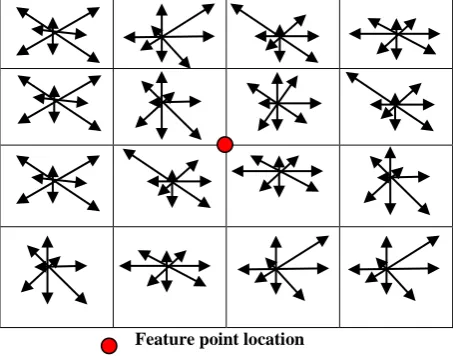
For panorama reconstruction to be distortion invariant, feature point descriptor should include locality information around the pixel. SIFT descriptor uses locality information. It uses gradient magnitude and phase at every pixel of the entire image using equation (5, 6). Orientation needs to be assigned to every feature point. For this, 7 by 7 grid locations around point is taken and phase of these selected grid locations are put in to one of 36 bins of each 10 degrees ranging from –pi to pi. In the selected bin, add the magnitude of gradient of corresponding grid location to the corresponding bin. The bin having maximum magnitude after dividing 49 grid location in to 36 bin can be used to assign orientation to that feature point i.e. orientation associated with that bin can be assigned to that feature point. If the 0.8(or 80%) of maximum magnitude is present in any other bin, then there will be two orientations assigned to that point. Consequently, there will be two feature descriptor vectors for that point.
For feature vector generation of a feature point, 16x16 grid locations are selected around that point. These 16x16 grid location are further divided into blocks of size 4x4. In this way, there will be 16 such blocks. In each block, the phase of grid locations with reference to the assigned orientation (i.e. subtraction of phase angle at each grid location and assigned orientation to corresponding feature point) are calculated and assigned to 8 bins of 45 degrees each ranging from -pi to pi. Also, Corresponding magnitude of that grid location gets added to that bin.
So, for each block there will be 8 histogram orientations and there are 16 such blocks in total. So, descriptor vector will be of length 16x8 = 128. For each feature point, there will be a
feature vector of length 128 to describe that feature point. Feature generation processes are shown in the Figure 5.
2.3 Feature point matching
Feature point correspondences between features of two or more input images can be established treating Euclidean distance between each input feature vector pair as parameter. Euclidean distance is defined using equation (7). If the ratio of minimum and second minimum Euclidean distance (i.e. ratio of closest match to second closest match) is less than
Figure 4: Result of feature detector using proposed technique
2 2
Magnitude (I(x 1, y) I(x 1, y)) (I(x, y 1) I(x, y 1)) (5)
1
Phasetan ((I(x, y 1) I(x, y 1)) / (I(x 1, y) I(x 1, y)))
(6) [image:3.595.319.539.186.333.2]
Feature point location
Figure 5: Feature vector generation process using histogram bins
predefined parameter distanceRatio, it can be treated as probable correspondence.
128 2 i i i 1
Dist an ce
(X Y )
(7)
Where Xi and Yi are the elements of feature vector of two
[image:3.595.320.547.426.604.2]Computational complexity can be further reduced by using Best-bin first (BBF) search algorithm as discussed in Lowe’s paper [11] which also returns the closest match with a higher probability.
2.4 Homography Matrix Calculation
Feature-point correspondence between two images provides homography transform matrix so that application of this transform matrix on appropriate image can bring all the input images in same camera co-ordinate system i.e. geometric distortions occurred due to change of camera orientation can be compensated using this matrix. Camera calibration includes two parameters, intrinsic as well as extrinsic parameters. Intrinsic parameter takes focal length, principal point, lens distortion, etc. into consideration whereas extrinsic parameter considers 3D position and orientation of camera. Here, extrinsic parameter has been taken into consideration for homography calculation.
1 2 3
4 5 6
7 8 9
h
h
h
x
X '
HX
h
h
h
y
h
h
h
1
(8)
Where '
(x',y',1)
TX and X
(x,y,1)
Tarethe homogeneous coordinates of two corresponding points and H is the homography matrix. From equation (8), it is clear that
h
7=h
8=0and there are 7 variables yet to be determined in this matrix. To solve for 7 unknowns, at least four correspondences pair ofX
'
andX
is required.There are many methods (such as LMS, RANSAC, etc.) discussed in the literature for computing this matrix. Here RANSAC has been used to find homography matrix computation. For computation using RANSAC, select 4 feature point correspondence randomly and calculate homography matrix. Now this matrix will be applied on other correspondence pair of feature points and mean square error (MSE) between each matching pair will be calculated as defined in equation (9). If the MSE for a pair is greater than defined threshold thresholdDistance, that pair will be treated as outlier otherwise, it will be an inlier. If the total number of inlier computed based on threshold is lesser than parameter inlinernumber, there is a need to choose another 4 different points (at least one should be different) and calculate Homography matrix again. This iteration will stop only when number of inlier satisfies inliernumber criteria or it can be stopped by fixing the number of iteration.
2 2
i j i j
MSE
(x
x )
(y
y )
(9)
Where P (xi,yi) and Q(xj,yj) is the correspondence pair.
2.5 Image Stitching
The panoramic view can be reconstructed by stitching the images which are now in the same camera coordinate system. Before stitching, there is a need to create frame which should be capable to fit the panoramic view. Application of homography transform may convert rectangular image in to quadrilateral form. So, there is a need to track the corners of each image to be stitched. After stitching, find the minimum and maximum of all the corners to determine the size of mosaiced frame. Let xmin and xmax is the minimum and
maximum x-coordinate respectively and ymin ,ymax are the
minimum and maximum y coordinate respectively of stitched image. Size of mosaiced frame can be calculated using equation (10, 11).
Width
(x
max
x
min)
(10)
Height
(y
max
y
min)
(11)
2.6 Image Blending
Mosaiced image may not be natural looking at the boundary due to illumination changes present in the input images. A good image blending technique is needed to make the panoramic view as natural as possible near the transition region. Methods are available to do this work: Linear blending, Multiband Blending, Cylindrical blending, pyramidal blending, etc. Since, this paper does not focus on blending, feathering technique of blending has been used which is the simplest one.
3. QUANTITATIVE EVALUATION OF
IMAGE MOSAICING
In the literature [15, 16], parameters for quantitative evaluation of image mosaicing technique are defined to compare the different techniques. In this paper, Normalized absolute error(NAE) and structural similarity index(SSIM) has been taken into consideration for performance evaluation comparison of proposed technique with the SIFT based technique. For a good image mosaicing technique, NAE value should be less and SSIM value should be large.
4. EXPERIMENTAL RESULTS AND
DISCUSSION
Table 1. Number of detected feature points using SIFT and Proposed technique
Image
Image Size Number of detected feature points
(SIFT)
Number of detected feature points(Proposed technique)
Left Image Right Image Left Image Right Image Left Image Right Image
Figure 6 381x334 381x336 441 455 389 702
Figure 8 718x932 691x1283 5591 6285 5430 6008
Figure 10 770x701 819x777 5851 4802 4296 3538
Figure 12 1185x901 1526x1302 5111 6736 2633 3264
Figure 14 1200x1331 1200x1041 9179 9012 2578 2252
Table 2. Computation time of image mosaicing using SIFT and Proposed technique
Image
Computation time (in second)
of Mosaicing using SIFT
technique
Computation time (in second) of Mosaicing
using Proposed technique
Figure 6 4.845 4.643
Figure 8 43.561 39.926
Figure 10 32.332 26.93
Figure 12 70.434 55.344
Figure 14 82.77 50.543
Table 3. Quantitative evaluation of image Mosaicing using SIFT and Proposed technique
Image
NAE SSIM
SIFT Technique
Proposed Ttechnique
SIFT Technique
Proposed Technique
Figure 6 0.0390 0.0399 0.8961 0.8953
Figure 8 0.5120 0.5108 0.0465 0.0471
Figure 10 0.5264 0.5241 0.0678 0.0670
Figure 12 0.3566 0.3570 0.3949 0.3951
Figure 14 0.0290 0.0261 0.9864 0.9890
5. CONCLUSION
Since image mosaicing is becoming popular in camera which is a real time application and it needs high computation time efficiency. In this paper, a technique of image mosaicing based on discrete-wavelet transform has been proposed which gives less number of interest points compared to other existing techniques which leads to improved computation time. According to table 3, performance of the proposed technique is either same or better compared to SIFT technique. So, proposed technique reduces simulation time while maintaining the quality of output image. Performance of this technique can also be verified by parameters like percentage of mismatches, peak signal-to-noise ratio, mutual information, etc. Quality of panorama can be further improved by selecting another blending techniques and computation time can be further reduced.
6. REFERENCES
[1] Rosebet Miranda-Luna, Daul, C., Blondel W.C.P.M., Hernandez-Mier, Y., Wolf and D.Guillemin F., “Mosaicing of Bladder Endoscopic Image Sequences: Distortion Calibration and Registration Algorithm,” IEEE Transactions on Biomedical Engineering, pp. 541-553, Vol. 55, no. 2, 2008.
[2] Samy Ait-Aoudi, Mahiou, R. Djebli and H.Guerrout, “Satellite and Aerial Image Mosaicing : A Comparative Insight,” 16th
International conference on information visualization, pp. 652 – 657, 2012.
[3] Jagjit Singh, “Image Mosaicing with Invariant Features Detection using SIFT,” Global Journal of Computer Science and Technology Graphics & Vision, vol. 13, issue 5, Version 1.0, 2013.
[4] http://www.imosaic.net/
[5] George Wolberg and Siavash Zokai, “Robust Image Registration Using Log-Polar Transform,” International Conference on Image Processing, vol. 1, pp. 493-496, 2000.
[6] Pengrui Qiu,Ying Liang and HuiRong, “Image Mosaics Algorithm Based on SIFT Feature Point Matching and Transformation Parameters Automatically Recognizing,” Proceedings of the 2nd International Conference on Computer Science and Electronics Engineering (ICCSEE), pp.560-63,2013.
International Journal of Computer Vision 74(1), pp. 59– 73, 2007.
[8] X. Dai and S. Khorram, “A feature-based image registration algorithm using improved chain-code representation combined with invariant moments,” IEEE Transaction on Geoscience and Remote Sensing, vol. 37 issue 5,pp.2351 - 2362, 1999.
[9] C. Harris and M. Stephens, “A combined corner and edge detector,” In proceeding of Fourth Alvey vision conference UK, pp. 147-151,1988.
[10] Stephen M. Smith and J. Michael Brady, “SUSAN—A New Approach to Low Level Image Processing,” International Journal of Computer Vision 23(1), 45–78, 1997.
[11] David G. Lowe, “Object Recognition from Local Scale-Invariant Features,” The Proceedings of the Seventh IEEE International Conference on computer vision, vol.2, pp.1150 - 1157, 1999.
[12] Deepak Kumar Jain, et al. “A novel still image mosaic algorithm construction using feature based method,”
International Journal of Electronics Signals and Systems (IJESS), vol. 3, issue1, 2013.
[13] Liu Qing and Lin Tu- sheng “The Corner Detection Algorithm Based on 2-D Discrete Wavelet Transform,” The 3rd International Conference on Innovative Computing Information and Control (ICICIC’08), pp. 178, 2008.
[14] T. X. He, “Biorthogonal spline type wavelets,” Computers & Mathematics with Applications, vol. 48, issue 9, pp. 1319-1334, 2004.
[15] Zhang Weibo, Li Jianxun and Zhang Zhi. “Performance Evaluation Approach for Image Mosaicing Algorithm,” Control and Decision Conference (CCDC), pp. 3786 – 3791, 2013.
[image:6.595.342.563.318.444.2][16] Hemlata Joshi and KhomLal Sinha, “Image Mosaicing using Harris, SIFT Feature Detection Algorithm,” International Journal of Science, Engineering and Technology Research(IJSETR), Issue 11, vol. 2, pp. 2078-2082, 2013.
Figure 6: Feature-point correspondences shown by connecting line between input images shown side-by-side
Figure 7: Final stitched image of input images
[image:6.595.64.571.512.729.2]
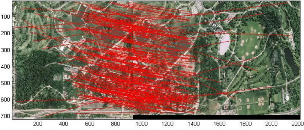
200 400 600 800 1000 1200 1400 100
200 300 400 500 600 700
800
[image:7.595.64.562.106.298.2]Figure 10: Feature- point Correspondences shown by connecting line between Input images shown side-by-side
5 0 0 1 0 0 0 1 5 0 0 2 0 0 0 2 5 0 0 2 0 0
4 0 0
6 0 0
8 0 0
1 0 0 0
1 2 0 0
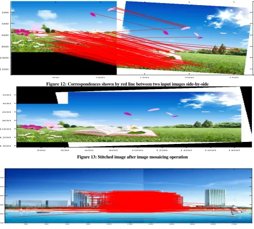
Figure 12: Correspondences shown by red line between two input images side-by-side
2 0 0 4 0 0 6 0 0 8 0 0 1 0 0 0 1 2 0 0 1 4 0 0 1 6 0 0 1 8 0 0
2 0 0
4 0 0
6 0 0
8 0 0
1 0 0 0
1 2 0 0
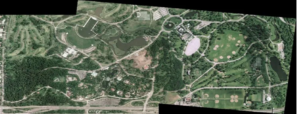
1 4 0 0
Figure 13: Stitched image after image mosaicing operation
200 400 600 800 1000 1200 1400 1600 1800 2000 2200
[image:8.595.58.554.86.533.2]200 400 600 800 1000 1200
Figure 14: Feature- point Correspondences shown by connecting line between Input images shown side-by-side
[image:8.595.67.551.558.694.2]