Design and Implementation of Fuzzy PID Controller for
Single Link Flexible Joint Robotic System using FPGA
Ekbal Hussein Ali,
Ph.D Computer Engineering Dept.University of Technology Baghdad, Iraq
Ekhlas Hameed Karam,
Ph.D Computer Engineering Dept.Al-Mustansyri University Baghdad, Iraq
Hussein Adheem Abbas,
Ph.D Computer Engineering Dept.University of Technology Baghdad, Iraq
ABSTRACT
Designing a Fuzzy Proportional Integral Derivative (FPID) controller that can control single link flexible joint robotic system which is nonlinear and have a complex mathematical model, led to the need of finding a way that could be efficient to hardware implementation, using Field – Programmable Gate Array FPGA (small device size, cost effective, short time to market, Reliability and Long – Term Maintenance) could solve that issue. Fuzzy Logic Controller (FLC) system is a most promising area for industrial application and by combining it with PID control algorithms features; they offer a high speed process using simple rules with the accuracy of PID tuning methods. In this paper, we have demonstrated the implementation of FPID controller using Very high speed integrated circuits Hardware Description Language (VHDL) code in FPGA, we have used Mamdani type as a FLC structure. The controller algorithm have been developed, synthesized, simulated and implemented on FPGA Spartan6, XC6SLX150T, FGG676 board.
Keywords
FPID, SLFJRS, VHDL, Hardware Implementation in FPGA.
1.
INTRODUCTION
Most industries use variety control systems to perform various tasks. PID controller is the most widely used strategy in nonlinear systems, around 95% of those systems, so it have been used for various control problems such as flexible joint robotic system [1]. Hence, three PID Tuning methods have been used, chosen according to their simplicity and robustness which are (robust PID, direct synthesis and simple controller approach) [2, 3, and 4]. Since, fuzzy logic offers several unique features that making it a particularly good choice for many control problems; we could obtain the high speed process using simple rules from Fuzzy Logic algorithm with the accuracy of PID tuning methods. Some of fuzzy logic features are: [5].
1. It is inherently robust since it does not require precise, noise-free inputs.
2. Since the processes are user-defined rules, it can be modified easily to improve system performance. 3. This controller can control nonlinear systems that would
be difficult or impossible to model mathematically As an adoption across all industries FPGAs has been intended in order to fill the gap between software and hardware, by combining the best parts of processor – based systems and ASICs, as a result, achieving much higher performance than software, in addition to maintain higher level of flexibility than hardware [6, 7, 8].
The motivation behind implementation FPIDC in FPGA using VHDL language that is because FPGA is advisable for quick hardware verification and fast implementation. So that
systems based on it are more flexible and could be reprogrammed with unbounded number of times. In addition to the rapid evolution of silicon technologies that helped to reduce the size of FPGA integrated circuits and its inexpensive cost, making, FPGAs could be used as a final solution to implement control systems like fuzzy PID controller [9].
We have proposed a simple FPID controller for a single link flexible joint robotic system, error and change of error in the velocity have been used as two inputs for the Fuzzy, Proportion, Derivative controller FPD; error and accelerated rate of error in the link angular displacement have been used as two inputs for the Fuzzy, Proportion, Integral controller FPI. The outputs of the two controllers are added to produce the controller action. For each one of the inputs there are 2 triangular membership functions (triangular membership function is a special case of the trapezoidal function) have been selected, for FPD output there are 2 triangular membership functions and for FPI 3 triangular membership functions have been selected. All these membership functions have been coded in VHDL.
An algorithm has been developed in VHDL to fuzzifie the crisp digital values of the inputs and to defuzzifie the outputs of FPD and FPI. Mamdani type FLC structure has been used to obtain the controller output. The controller algorithm developed, synthesized, simulated and implemented on FPGA Spartan6 family, XC6SLX150T device, FGG676 package. FPID has been designed using Hybrid Programming Platform technique. The results of the implemented FPID controller using FPGA have been compared with the results that obtained using the same controller structure on Matlab Simulink.
2.
SYSTEM DESCRIPTION
In many robotics applications, the joint flexibility cannot be neglected. The presence of flexibility can cause poorly damped oscillations. These oscillations may degrade the performance of the system and lead to instabilities in some extreme cases. Therefore, the joint flexibility should be taken into account in any realistic robotic modeling [10].
Considering a single link rotating on a horizontal plant and actuated with a motor through an elastic joint coupling [11]. Let 1 be the link angular displacement (which considered as
the output to be controlled) and 2 be the motor angular
position. Then, typical flexible joint robotic arm model (see Fig. 1) can be described by the dynamic equations, [12, and 13].
Where, I is the link inertial, J is the rotor inertia, K is the stiffness, M is the link mass, g is the gravity constant, and l is the center of mass. The control input u is the torque delivered by the motor.
Fig. 1: Single link flexible joint robotic arm [13].
[image:2.595.58.281.128.279.2]The transfer function, in s-domain, of the system is given by [12, 13]:
…..(2) There are many researches which considered different data values as system parameters. Due to the case-study we considered the following values from [14], because the remaining researches proposed a very small values which need a simple controller to obtain the desired result, also from the experiment it observed by adding a small gain, system response became much batter and very near to the desired response which don’t need any fuzzy controller action. The values and symbols of system parameters are summarized in (Table 1).
Table (1): Values and Symbols of Single-Link Flexible Joint Parameters
Symbol Description Value
I Inertia of flexible manipulator 0.030 kgm2 J Inertia of rotational platform 0.004 kgm2 G Gravitational acceleration 9.81 N/m
L
Distance to center of gravity of rotational platform of flexible manipulator
0.135 m
M Mass of the flexible joint 0.6 Kg
Mgl M × L × G 0.800 Nm
K Flexibility coefficient of joint 31.00 Nm/rad
With these data, equation (2) becomes:
…..(3)
In order to check the system stability, we have defined equation (3) in the Matlab, and it shows that the system has all
poles on the imaginary axis, which means that the system has a critical stability features. ± 93.7362i and ± 4.8487i.
3.
IMPLEMENTATION OF FLC IN
VHDL
The motivation behind using Mamdani style as a method in designing FLC, because of its simplicity and compatibility with human made decision, this method is widely used in FLC in spite of having some drawback, so that, this method requires finding the centroid of a two-dimensional shape. But in our design we have overcome this issue by choosing the membership functions for the inputs and the output of triangular and trapezoidal membership. It gives much accurate output, this due to using membership functions in obtaining the output comparing with other type such as sugeno style which gives a unity at a single particular point. FLC algorithm has been coded in VHDL and implemented in Xilinx ISE Design Suite 14.6.
3.1
Fuzzification
This component of the proposed FLC comprises the process of converting the crisp values into grades of membership in the interval [0,1] in the corresponding fuzzy sets; this could be achieved using triangular fuzzifier. As mentioned in a previously each one of the two FLCs (FPI and FPD) have two inputs one output, each input is represented by two membership functions, so that:
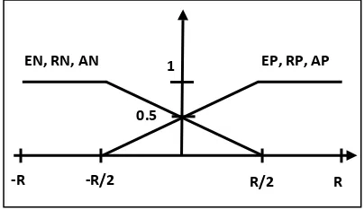
Fuzzy set 'error' has two memberships EN (negative) and EP (positive).
Fuzzy set 'rate' (rate of change of error) has two memberships RN (negative) and RP (positive).
Fuzzy set 'acc' (accelerated rate of change of error) has two memberships AN (negative) and AP (positive). (see Fig. 2).
Concerning the output, FPD controller output represented by three membership functions:
Fuzzy set 'FPD_O' has three memberships FPD_ON (output_negative), FPD_OP (output_positive) and FPD_OZ (output_zero) (see Fig. 3).
And FPI controller output represented by two membership functions:
Fuzzy set 'FPI_O' has two memberships FPI_ON (output_negative) and FPI_OP (output_positive) (see Fig. 4).
All these functions have a range that could be specified according to the system requirements by tuning range selection lines to cover the satisfied range.
Fig. 2: FLCs' inputs membership functions
1 EP, RP, AP EN, RN, AN
-R -R/2 R/2 R
[image:2.595.327.529.632.749.2]Fig. 3: FPD controller output membership function
Fig. 4: FPI controller output membership function.
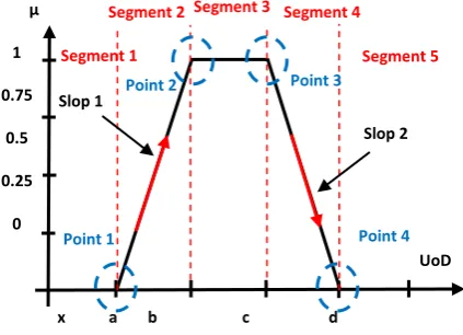
[image:3.595.61.273.423.576.2]In VHDL, each trapezoidal membership function defined by two reference points and by two slops values, so, the entire function could be divided into five segments as explained in Fig.5:
Fig. 5: Trapezoidal type membership functions
The degree for the membership (µ) could be calculated according the five segments:
1. In segments 1 and 5: µ = 0.
2. In segment 2: slope is upward from left to right, i.e.: µ = (input value – a) × slope1, where µ is limited to maximum value of 1, where slope 1 = – .
3. In segment 3: µ = 1.
4. In segment 4: slope is downward from right to left, i.e.: µ = 1 - (input value – d) × slope2, where µ is limited to maximum value of 0, where slope 2 = – .
3.2
Fuzzy Inference Rules
Fuzzy control rule have been made based on expert experience and control engineering knowledge, and each control rule set of the two FLCs compresses of four fuzzy control rules, so that for FPD controller:
(R1)FPD: IF error = EP AND rate = RP THEN output = FPD_OP (R2)FPD: IF error = EP AND rate = RN
THEN output = FPD_OZ (R3)FPD: IF error = EN AND rate = RP
THEN output = FPD_OZ (R4)FPD: IF error = EN AND rate = RN
THEN output = FPD_ON And for FPI controller:
(R1)FPI: IF error = EP AND acc = AP THEN output = FPI_OP (R2)FPI: IF error = EP AND acc = AN
THEN output = FPI_ON (R3)FPI: IF error = EN AND acc = AP
THEN output = FPI_OP (R4)FPI: IF error = EN AND acc = AN
THEN output = FPI_ON
As mentioned previously we have considered Mamdani type as FLC style, so that AND gate gives the minimum of two values. For example, when the value of the two inputs of FPD (error and rate) are given, and let the membership values which obtained by using the fuzzification algorithm given by (Fig. 2) be as µEP and µRP, then, in rule (R1)FPD for example, the output membership value associated is the Min (µEP,µRP).
3.3
Defuzzification
This part of fuzzy controller converts the value from linguistic variables to crisp value. The "centroid" method is very popular, in which the "center of mass" of the result provides the crisp value, i.e. after the output of each rule have been identified, this component process those values to produce one single value for each discrete case, this is done according to equation (4)
….(4) Where:
n : is the number of rules.
µu(n) : is the membership value of the output n. y : is the control output as a crisp value.
4.
SIMULATION AND RESULTS
Simulation in MATLAB/SIMULINK
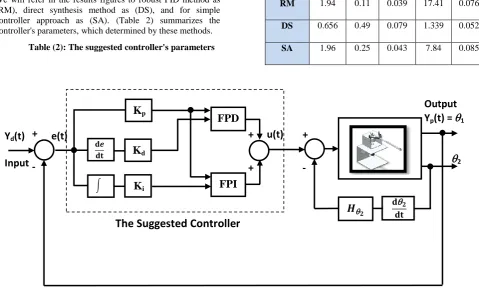
Simulation has been done for single link flexible joint robotic system using PID and FPID controller in Matlab Simulink. (see Fig. 6), it describes the block diagram for the closed loop control system with the suggested controller.
The comparisons of FLC have been done with PID controller expressed by:
Point 1 Point 4
UoD µ
x a b c d y
Segment 2 Segment 3 Segment 4
Slop 2 Slop 1
Segment 1 Segment 5
1
0.75
0.5
0.25
0
Point 2 Point 3
1 FPI_OP
FPI_ON
-RPI -RPI/2 RPI /2 RPI
0.5 0.5
1
FPD_OP FPD_ON
-RPD -RPD/2 RPD/2 RPD
….(5) We will refer in the results figures to robust PID method as (RM), direct synthesis method as (DS), and for simple controller approach as (SA). (Table 2) summarizes the controller's parameters, which determined by these methods.
Table (2): The suggested controller's parameters
Methods Name
Kp Ti Td Ki Kd
RM 1.94 0.11 0.039 17.41 0.076
DS 0.656 0.49 0.079 1.339 0.052
[image:4.595.59.539.99.387.2]SA 1.96 0.25 0.043 7.84 0.085
Fig. 6: Block diagram for the overall suggested controller system
The step unit response with amplitude of (5) was considered to test the system performance with PID controller and the suggested FPID controller (see Fig. 7 and Fig. 8).
[image:4.595.319.548.425.588.2]Fig. 7: Output response for single link flexible joint robotic system with PID controller.
Fig. 8: Output response for single link flexible joint robotic system with FPID controller.
(Table 3) shows the performance of the suggested controller, when applied to the closed loop of the single link flexible joint robotic system:
Table (3): The suggested controller's parameters
Controller type Mp ts tp
PID
RM 43 1.9 0.39
DS 15.8 5.8 0.78
SA 23.9 2.72 0.48
FPID
RM 20 1.7 0.2
DS 0 5.8 0.28
SA 12 1.8 0.2
FPID_VHDL DS 43 1.9 0.39
0 1 2 3 4 5
0 2 4 6 8 Time (sec) L in k a n g u la r p o s it io n (r a d ) RM DS SA Des
0 1 2 3 4 5
0 2 4 6 8 Time (sec) L in k a n g u la r p o s it io n (r a d )
RMFLC
DSFLC
SAFLC
Des
e(t)
+
u(t)
+
Y
d(t)
Input
K
pFPD
Output
Y
p(t) =
1
2FPI
The Suggested Controller
[image:4.595.59.289.468.637.2] [image:4.595.324.539.661.768.2] Simulation in XILINX ISE
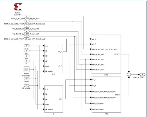
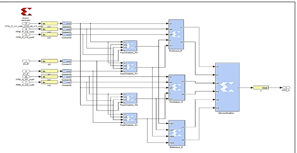
Simulation has been done for single link flexible joint robotic system with FPID controller in Xilinx ISE Design Suite 14.6 using Hybrid Programming Platform technique. (see Figure 9, 10) they show the Simulink diagram of the proposed controller using system generator and the Register Transfer Level RTL view of FPID respectively. Using robust tuning method's parameters, (Figure 11) shows the response of the implemented controller named as (RM-16FBC) compared with one simulated in Matlab named as (RM_FLC).
The proposed controller has five 8-bit lines, which are used to scale the range of the input output membership functions. Three 8-bit PID parameters setting line. The suggested controller consists of four parts: PD, I parts which represents
the conventional PID controller (see Figure 12, 13) respectively, FPD part which contains the FPD controller (see Figure 14), and FPI part which contains the FPI controller (see Figure 15), finally the output of the two fuzzy controller are added to produce FPID output signal which controls the system.
[image:5.595.61.541.237.619.2]Each black box of the design calls the relative VHDL code file which has been assigned to process a specific job, i.e. concerning FLCs there are fuzzification, rule base and defuzzification boxes which operates according to its own VHDL code file. All system input values are going through a gateway in to the black boxes, the output flow is going through a gateway out, and finally the control output signal is obtained by adding the two FLCs outputs.
Fig. 10: RTL View of FPID using VHDL in Xilinx
[image:6.595.55.539.72.514.2]ISE Design Suite 14.6
Fig. 11: System response using FPID and FPID-VHDL
using System Generator
Fig. 12: I structure using Xilinx system generator Fig. 13: PD structure using Xilinx system generator
Fig. 14: FPD structure using Xilinx system generator
0 1 2 3 4 5
0 1 2 3 4 5 6
Time (sec)
L
in
k
a
n
g
u
la
r
p
o
s
it
io
n
(r
a
d
)
[image:6.595.323.533.73.255.2] [image:6.595.59.542.484.733.2]Fig.15: FPI structure using Xilinx system generator
5.
CONCLUSION
For designing FPID controller, a High-Level modeling approach have been used in VHDL, the aspects of this is to reducing the design time, quickly exploring of different design choices, and the ease maintenance and upgrading of the design so that each part could be checked and enhanced separately which give the ability of evolution of the design functionality. The implementation of the FLC is straight forward by coding each one of its component in VHDL according to the required specification, the five 8-bit selection lines is to meet the system requirement so the Universe of Discourse (UoD) could be from -255 to +255.
The suggested method (which is simple and not need huge computation) has been applied on a single link flexible joint robot system. The new interaction PID-FC methods make the output response is more accurate in tracking the desired input, so in order to show the efficiency of the suggested method we have select a step unit of (5) amplitude, and from (Table 3) we could observe that the output response has a zero steady state error, small overshoot, and small settling time.
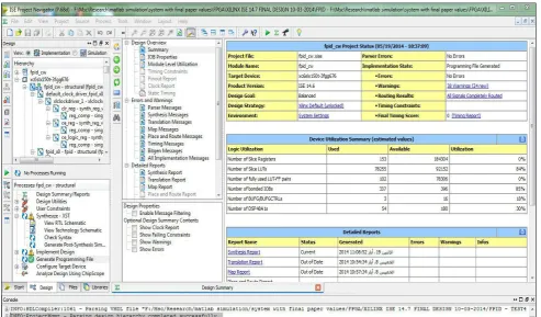
Form Xilinx ISE Design Suite 14.7 design summary (see Fig. 16) we notice that we have occupied 85% of the chip resources as a maximum.
[image:7.595.54.548.451.740.2]6.
REFERENCES
[1] Teranun T., et al., 2006. "Geno-fuzzy P2ID Control System for Flexible-joint Robot arm". Department of Information Engineering, Faculty of Engineering King Mongkut’s Institute of Technology Ladkrabang, Chalongkrung .Rd., Ladkrabang, Bangkok, Thailand 10520.
[2] Ismail H., et al., 2012, "Cascade fuzzy logic control of a single-link flexible-joint manipulator". Department of Mechatronics Engineering, Faculty of Engineering, Kocaeli University, Umuttepe 41380, Kocaeli-TURKEY. Turk J Elec Eng & Comp Sci, Vol.20, No.5.
[3] Dan C. and Dale E., 2002. "PI/PID Controller Design Based on Direct Synthesis and Disturbance Rejection", Department of Chemical Engineering, University of California, Santa Barbara, California 93106
[4] Nahida N., 2013. "Simple Controller Approach with Smith Predictor for Long Time Delay Systems" Journal of Engineering and Development, Vol. 17,No.2, ISSN1813, 7822
[5] Sekhar R., 2010, MSc thesis of "Design & Development of a Pic 16f877a Based Fuzzy Temperature Controller " Department of Electronics & Tele-Communication Engineering, Jadavpur University, Kolkata-700032, West Bengal, India
[6] Katherine C. and Scott H., 2000 "An Introduction to Reconfigurable Computing" Invited Paper, IEEE Computer.
[7] Karthigaikumar P., 2006, "A Novel FPGA Architecture for a Reconfigurable ALU", Academic Open Internet Journal, ISSN 1311-4360, Volume 19
[8] Thompson M., 2004, "FPGAs Accelerate Time to Market for Industrial Designs," EE Times.
[9] Ammar A., 2012 "FPGA Based Modified Fuzzy PID Controller for Pitch Angle of Bench-top Helicopter" Iraq J. Electrical and Electronic Engineering, Vol.8 No.1. [10]Akbari M., et al. 2011 "Nonlinear H∞ controller for
flexible joint robots with using feedback linearization" International Journal on Computer Science and Engineering (IJCSE), ISSN: 0975-3397, Vol. 3, No. 2. [11]Farid M. and Benjamin C., 2009 "Automatic Control
Systems", 9th edition book, Vancouver, British Columbia, Canada, JOHN WILEY & SONS, INC. [12]Adel M., Jason G., 2009, "Generalized Predictive
Control for Single-Link Flexible Joint Robot"; international Journal of Sciences and Techniques of Automatic Control & Computer engineering, IJ-STA, pp. 890-899, Volume 3, No.1.
[13]An-Chyau H. and Yuan-Chih C., 2004, "Adaptive Sliding Control for Single-Link Flexible-Joint Robot with Mismatched Uncertainties"; IEEE Transactions on Control Systems Technology, Vol. 12, No. 5.