Research on Control of Ignition and THC Formation in
CNG Engines by the Application of Gas-jet
Direct-ignition Technique
A thesis submitted in fulfillment of the requirements for the award of the degree of
Doctor of Engineering
September 2012
Department of Ecosystem Engineering
Graduate School of Advanced Technology and Science The University of Tokushima, Japan
Table of Contents
Abstract………..….. iv
Nomenclature……….. vi
Chapter 1 Introduction ... 1
1.1 The Rise of Crude Oil Price ... 1
1.2 Fossil Fuel Combustion Pollutants ... 2
1.3 Hydrogen as an Ideal Fuel and its Technical Challenges ... 3
1.4 Natural Gas as an Alternative Fuel ... 5
1.5 Global Gaseous Fuels Energy Source ... 8
1.6 Demand of Natural Gas Engines... 10
1.7 Combustion Characteristics of CNG Engines... 12
1.8 Methods of Realizing CNG Lean Combustion ... 14
1.9 Contents of Thesis ... 15
Chapter 2 Characteristics of Gas-jet Direct-ignition in CNG Combustion ... 17
2.1 Concept of Gas-jet Direct-ignition Method ... 17
2.2 Timing of Gas-jet Injection and Ignition ... 22
2.3 Application of Gas-jet Ignition Method to a CNG Engine ... 24
Chapter 3 Experimental Setup and Analysis Method ... 26
3.1 Test Engine for the Gas-jet Ignition Technique ... 26
3.1.1 Engine Specifications ... 26
3.1.2 Gas Injector and Spark Plug Layout ... 29
3.1.3 Test Equipments and Procedures ... 30
3.2 Gas-jet Injection Schlieren Imaging ... 32
3.3 Fuel-air Mixture Prediction by CFD Calculation ... 34
3.3.1 CFD Calculation Setup ... 34
3.3.2 Calculation Validation ... 37
3.4 CVC Experiment Setup for Flame Observation ... 38
Chapter 4 Improvement of Engine Performance Employing Gas-jet Ignition and Two-stage Gas Injection ... 42
4.1 Engine Performance Employing Premixed-type Ignition ... 42
4.2 Optimization of Gas-jet Injection and Ignition ... 44
4.3 Engine Performance Employing Gas-jet Ignition ... 47
4.4 Engine Performance Employing Gas-jet Ignition with Two-stage Gas Injection ... 48
4.6 Effect of First Injection Timing and Fuel Delivery in Lean Combustion at =0.8 ... 53
4.7 Effect of First Injection Timing and Fuel Delivery in Lean Combustion at =0.5 ... 58
4.8 Analysis of Hydrogen Addition Effect on Engine Performance by Two-stage Injection at =0.8 ... 61
4.9 Analysis of Hydrogen Addition Effect on Engine Performance by Two-stage Injection at =0.5 ... 66
Chapter 5 Mixture Distribution Prediction by CFD Computation ... 69
5.1 Description of Calculation Results ... 69
5.2 Analysis of Early Phase First Injection Timings for Two-stage Injection at =0.8 .. 70
5.3 Analysis of Late Phase First Injection Timings for Two-stage Injection at =0.8 .... 74
5.4 Analysis of First Injection Timings for Two-stage Injection at =0.5 ... 78
Chapter 6 Flame Development Observation by CVC Experiment ... 83
6.1 Gas-jet Ignition Flame Development Image Observation and Analysis ... 83
6.2 Effect of Hydrogen on Flame Development ... 86
6.3 Combustibility of Gas-jet Ignition with Two-stage Injection ... 90
6.4 Effect of Hydrogen Addition on Gas-jet Combustibility ... 92
6.5 THC of Gas-jet Ignition with Two-stage Injection ... 94
Chapter 7 Conclusions ... 98
References………..…101
Appendix………...……….…108
Abstract
Increasing world energy demand and recent climate change due to global warming have led us to search for sustainable energy sources with the lowest possible greenhouse-gas emissions. Our main energy, which sources from fossil fuel, is not sustainable and its combustion produces high content of harmful emissions. Hydrogen is always thought to be an ideal fuel because it is clean, renewable, and has abundant energy sources. Apparently, before hydrogen can be realized as the main energy source, a few major problems, such as the real-time production, safe and convenient storage, efficient combustion of hydrogen gas, and high
production cost, need to be addressed. While waiting for the hydrogen technology to mature, the use of other types of gaseous fuel to combat the greenhouse-gas emissions deem necessary. Natural gas is not a renewable fuel but it has abundant resources and the lowest average specific CO2 emission among the non-renewable fossil fuel energy resources.
Gas engines are typically utilized for electric power generation but are becoming popular in transportation sector. Recent statistical data obtained from NGV Global shows the worldwide growth of NGVs is increasing exponentially. A CNG engine is usually operated in the lean mode where equivalence ratio is between 0.7 and 1.0 by employing premixed-type
ignition technique. The CNG lean-burn approach has the advantage of high thermal efficiency, low NOX emission, and lower fuel consumption compared to stoichiometric combustion.
However, CNG lean combustion has problems such as poor ignitability and poor flame propagation which cause high cyclic variation, misfires and high THC emission. Using the lean-burn approach, the ignitability of the first flame core relies on local fuel-air mixture concentration near the ignition position. Too rich or too lean local mixture will cause the first flame core to quench before it begins to propagate to other parts of the combustion chamber. It causes poor combustion quality, misfires and higher cycle-to-cycle variations.
flame core development. Through experiments, it was found that the gas-jet ignition method was able to operate in ultra lean mode at equivalence ratio less than 0.3. To enable engine operation at equivalence ratio between 0.3 and 0.8, gas-jet ignition with two-stage injection method has to be implemented. The second gas injection followed by ignition similar to the gas-jet ignition, ensures ignitability. The first injection is delivered early similar to the premixed-type ignition method to create non-heterogeneous mixture to sustain flame development from the kernel initiated by the gas-jet ignition.
In the application of gas-jet ignition with two-stage injection using a real engine, the ignitability, combustibility and THC formation were investigated by varying the first injection fuel delivery timing. Moreover, the effect of hydrogen addition to CNG fuel on the ignitability, combustibility and THC formation were also investigated. The fuel-air mixture distribution inside the combustion chamber prior to ignition timing was calculated using CFD software to provide hints on the combustion cyclic variability and THC formation found during the engine tests. Furthermore, flame of the gas-jet ignition with two-stage injection
combustion was observed using a constant volume chamber.
It was found that the gas-jet ignition and gas-jet ignition with two-stage injection methods are effective to extend lean combustible ranges of CNG engines. The first injection timing in the two-stage injection method is a key factor to the better engine performance because it affects flame development after ignition. The combustion cyclic variation and THC emission are sensitive to mixture distribution in clearance space of the combustion chamber
Nomenclature
Acronyms
A/D: Analog to Digital
ATDC: After Top Dead Center BDC: Bottom Dead Center
BMEP: Brake Mean Effective Pressure CA: Crank Angle
CCS: Carbon Capture and Storage CFD: Computational Fluid Dynamics CH4: Methane
CLD: Chemiluminescence Detector CNG: Compressed Natural Gas CO: Carbon Monoxide
CO2: Carbon Dioxides
COV: Coefficient of Variation CVC: Constant Volume Chamber EI: Emission Index
FID: Flame Ionizer Detector fps: Frame per second GHG: Greenhouse Gas
GREET: Greenhouse gases, Regulated Emissions, and Energy use in Transportation H2: Hydrogen
H2O: Water
HC: Hydrocarbon HD: Heavy duty
HRR: Heat Release Rate
IMEP: Indicated Mean Effective Pressure IP: Ignition Probability
IPCC: Intergovernmental Panel on Climate Change LD: Light Duty
MD: Medium Duty
NDIR: Non-dispersive Infrared Absorption NGV: Natural Gas Vehicle
NGVA: Natural and Bio Gas Vehicle Association (Europe) Nm3: Normal cubic meter
NMHC: Non Methane Hydrocarbon NOX: Nitrogen Oxides
NTP: Normal Temperature and Pressure (293.15K, 1atm) O2: Oxygen
pdf: probability density function PM: Particulate Matters
ppm: parts per million RE: Renewable Energy RFG: Reformulated Gasoline SI: Spark Ignition
SOX: Sulfur Oxides
TDC: Top Dead Center THC: Total Hydrocarbon TWh: TeraWatts.hour
UNEP: United Nations Environment Programme UPS: United Parcel Service
WMO: World Meteorological Organization ZCR: Z-crankshaft
Abbreviations Vol: Volume Ign: Ignition
Symbols
h: Clearance height (mm) n: Engine speed (rpm) p: pressure (MPa) t: time
Q: heat
: Global equivalence ratio
g: Local equivalence ratio at spark ignition point L: Local equivalence ratio
c: Combustion efficiency (%) i: Indicated thermal efficiency (%)
Chapter 1
Introduction
1 Introduction
1.1 The Rise of Crude Oil Price
Energy and environmental issues are two relevant and heavily concerned issues worldwide. These two issues play an important part in our economy and health. It also affects the living of our future generations. Our main energy, which sources from fossil fuel is increasing in demand but depleting in supply. The increasing in demand is due to world development and technology advancement. Recently, such unbalance supply-demand
equation creates major global economic turmoil by sudden changes in oil price.
Figure 1-1 shows the crude oil historical price from 1980 to 2011, and price projections from 2011 to 2030. The price shown is in US Dollars per barrel. From the figure, the price of oil changes drastically between year 2007 and 2009. Overall, the crude oil price shows an increasing trend. This trend translates to insecurity of the cost and availability of the fossil fuel in the near future. Thus, in recent years, many countries try to lessen their dependency on
[image:9.595.169.471.534.745.2]fossil fuel by adopting alternative energy sources [1-5].
1.2 Fossil Fuel Combustion Pollutants
Any fossil fuel, typically diesel and gasoline combustion produces high content of harmful emissions. The primary combustion product, i.e. carbon dioxides (CO2) is a part of
greenhouse gases known to elevate global warming. In Fig. 1-2 below, the global CO2
emission from the burning of fossil fuel including gas flaring is shown. In the mid 1940s, the CO2 emission started to increase rapidly. The petroleum extraction and consumption
accelerated at the end of World War II in 1945, which marks the beginnings of the cold war,
the Bretton Woods system and decolonization [7, 8]. Since then the global CO2 emission has
increased to more than 4 folds reaching towards 30Gt CO2. Most of us are already on alert but
whatever we do or did, it seems that the CO2 emission problem is beyond our control and is
[image:10.595.91.535.387.583.2]kept getting worse.
Fig. 1-2 Global CO2 emission from fossil fuel burning from 1850 to 2007 [9]. The unit is in Gigatonne
CO2. Gas fuel includes flaring of natural gas.
Some of the known combustion byproducts are carbon monoxides (CO), unburned hydrocarbon (HC), soot, Nitric Oxides (NOX), Sulfur Oxides (SOX) and oxides of metals [10].
the main cause of smog and acid rain. Smog – coined from the term smoke and fog – is a type of air pollution. Acid rain which is also caused by SOX is harmful to plants, aquatic animals
and building. The environmental change, caused by human activities, that occurs over several decades, may also undermine the life-supporting functions of Earth [11-15].
The fights on these harmful emissions have been going on for ages but the earth seems always on the losing side. Now we are facing worsen climate and more natural disaster due to global warming. Our environment is kept on getting worse despite many pollution control attempts. No matter how tiny it may seems, any alternative sources of renewable, clean and abundant energy might help cushioning the fall.
1.3 Hydrogen as an Ideal Fuel and its Technical Challenges
The key criteria of an ideal fuel are inexhaustibility, cleanliness, convenience, and independence from foreign control. Hydrogen (H2) fits all the given criteria and thought to be
the best option for clean renewable and abundant energy source [16-20]. Over the past 40 years, hydrogen is being promoted by environmentalists and several organizations as a total solution for the air pollution and global warming problems. Ideally, hydrogen may replace gasoline, heating oil, natural gas and other fuels in both transportation and non-transportation applications.
Fig. 1-3 Hydrogen production pathways [22, 23]
The particular attraction of hydrogen lies in the fact that it can be obtained from water and that during combustion it oxidizes to water again. Hydrogen is the only fuel that permits propulsion entirely free of pollutant emissions except for a low level of NOX. It is the only
fuel which does not contain carbon-based elements, thus avoiding emissions such as CO2, CO,
HC and particulate matters. The combustion of hydrogen is given as:
2H2 + O2 => 2H2O (2 hydrogen + oxygen => 2 water)
Apparently, before hydrogen can be realized as the main energy source, a few technical and economical problems or challenges that need to be addressed [24]. Hydrogen main technical challenges are the real-time production, safe and convenient storage, and efficient combustion of hydrogen gas. The major economic challenge is the cost of hydrogen production, which is currently higher than the cost of petroleum extraction. Apart from those, the socio-political problem also plays their part inhibiting hydrogen usage, such as public awareness and governmental policies.
Differently, according to Romm [20], hydrogen should be utilized as an energy carrier
discussed in this text. Summaries of hydrogen research and development can be found in these references [20, 25-27].
1.4 Natural Gas as an Alternative Fuel
While waiting for the hydrogen technology to mature, the use of other types of gaseous fuel, specifically natural gas, to combat the greenhouse-gas emissions deem necessary. In addition, the use of natural gas is also cost effective because the technologies and infrastructures available to date favor the producing and utilization of natural gas instead of hydrogen. The awareness of these facts promotes rigorous researches and development on natural gas combustion.
Natural gas is odorless, colorless, and tasteless in its pure form. It consists mostly of methane (CH4) and is drawn from gas wells or in conjunction with crude oil production.
Besides methane, Natural gas may also include ethane, propane, butane and pentane. Compressed natural gas (CNG) is made by compressing natural gas to less than 1% of the volume it occupies at standard atmospheric pressure.
Although natural gas is not a renewable fuel, natural gas has plentiful resources. As of January 2009, World Proved Reserves of Oil and Natural Gas stated that world natural gas reserved has the capacity of 6342 trillion cubic feet while oil reserved has the capacity of 1,342 billion barrels [28, 29]. Natural gas also has clean burning characteristics compared to other type of fossil fuel.
reformulated gasoline (RFG) in light duty (LD) vehicles and to replace diesel fuel in heavy duty (HD) vehicles. In some countries, gasoline volatility is regulated in large cities to reduce the emission of unburned hydrocarbons by the use of RFG that is less prone to evaporation. The reduction of exhaust non methane hydrocarbon (NMHC) when CNG replaces RFG is only 10%.
The study on CNG replacement in diesel engines were done on a fleet of UPS delivery trucks in the US by collaboration between Battelle, NREL and West Virginia University. The data shown in Table 1-1 is taken from chassis dynamometer test by West Virginia University.
The CO reduction when CNG replaces diesel is almost doubled compared with gasoline in spark ignition (SI) engine in hybrid vehicles. The NOX reduction is 49% and the exhaust PM
[image:14.595.99.525.405.506.2]reduction is near to 100%. However, the use of CNG in SI engines releases unburned methane as much as 400%.
Table 1-1 Percentage of pollutant reduced when CNG replaces gasoline and diesel
Pollutant Reduction SI Engines [30] SI Hybrid [30] UPS Delivery Trucks [31]
Exhaust NMHC reduction 10% 10% 4%
CO reduction 20% 40% 75%
NOx reduction 0% 0% 49%
Exhaust PM reduction 80% 50% 95%
Methane reduction -400% -400% Not measured
Life cycle analyses provide most sensible comparison for greenhouse gas emission of various energy sources. The life cycle analyses takes into account the effects of producing and transporting fuel, building and subsequently decommissioning facilities, generating power, and treating and disposing of waste [32]. Figure 1-4 shows specific CO2 emission in terms of
weight of CO2 equivalent per output power, for several energy sources. From the figure,
natural gas has lowest average specific CO2 emission among the non-renewable fossil fuel
Fig. 1-4 Specific CO2 emission via lifecycle analyses [9]
Table 1-2 Properties of methane and hydrogen [34-37]
Properties Methane Hydrogen
Density at NTP (kg/m3) 0.65119 0.083764
Lean ignition limit () in NTP air 0.53 0.10
Volumetric lower heating value at NTP (kJ/m3) 32,573 10,046
Volumetric lower heating value in air at NTP (=1) 3,088 2913
Laminar burning speed in NTP air (cm/s) 37–45 265–325
Quenching distance in NTP air (cm) 0.203 0.064
Adiabatic flame temperature in air (K) 2148 2318
[image:15.595.120.503.561.717.2]CNG is a slow burning fuel, which is known to have performance and emission issues during lean combustion. Referring to Table 1-2, hydrogen has about seven-time faster burning speed than CNG. It has been shown that mixing some percentage of hydrogen to CNG fuel is known to improve the combustion of lean burn CNG engines [34, 38, 39]. However, because of the percentage of hydrogen addition determines the resulting burning speed, the time interval between fuel injection and ignition plays an important role in producing optimum mixture distribution thus producing quality combustions [40-43].
According to many researchers, hydrogen addition to CNG was found to reduce combustion lean limit to a leaner equivalence ratio. Other results showed improvements in higher thermal efficiencies, higher BMEP, reduction of CO, CO2 and THC emissions from the
combustion [35, 36, 40, 44, 45]. Hydrogen addition to CNG also increases the combustion speed and the combustion temperatures, which may result in increased NOx emissions compared to pure CNG at the same equivalence ratio [46].
1.5 Global Gaseous Fuels Energy Source
Our global energy consumption is being closely monitored by the Intergovernmental Panel on Climate Change (IPCC). The IPCC consists of 194 countries and was established by the United Nations Environment Programme (UNEP) and the World Meteorological Organization (WMO). Their mission is to provide the world with a clear scientific view on the current state of knowledge in climate change and its potential environmental and socio-economic impacts.
Fig. 1-5 Global primary energy supply in 2008 [9]
[image:17.595.90.540.411.663.2]Figure 1-6 shows the percentage and amount of energy source (in TeraWatts.hour) for global electricity generation. The renewable energy source is only 18.4% and is mainly by hydropower. Energy from fossil fuel is dominated by coal at 41.1% and followed by natural gas at 21.4%. Comparing both Fig. 1-5 and Fig. 1-6 suggested that oil is widely used in mobile energy supply, namely in transportation, instead of in stationary electricity energy generation. Maybe there is energy source or energy transport using hydrogen fuel in year 2008 but the quantity is too small compared to other types of fuel. On the other hand, the use of gaseous fuel, especially natural gas, is more being utilized in both mobile and stationary
energy generations.
1.6 Demand of Natural Gas Engines
A gas engine is an engine running on gaseous fuel(s), such as coal gas, biogas, natural gas and hydrogen. Gas engines have been around since 19th century and typically utilized for electric power generation. In modern days, the use of natural gas engines is becoming popular in transportation sector [47-49]. Figure 1-7 shows worldwide NGV actual growth from 1991 to 2011 and projection from 2006 to 2014. This statistical data was obtained from NGV Global; the International Association for Natural Gas Vehicles. The vertical axis in the figure shows numbers of NGVs. From the three trendlines shown, the worldwide growth of NGVs is best fitted by the exponential trendline. It is an indication that the worldwide market share of NGVs is increasing rapidly.
Table 1-3 W Country Natural gas countries Rest of the world World total Fig. 1 Worldwide N Human population (million) 5944.28 1029.75 6974.03
1-7 NGVs gr
NGV shares Total vehicles per 1000 human populatio 178 5 152 rowth worldw
in total LD,
0 n NGVs pe 1,000 human populatio 2 0 2
wide from ye
MD and HD
er n on Total ve popula 1,056,26 5,148 1,061,41
ear 1991 [50]
D vehicles ma
ehicle ation Tot pop 63,362 14, ,763 12,125 14, ]
arket in 2012
tal NGV pulation
N s
253,074 1
0 0
Table 1-4 Top ten countries with largest NGVs and their fuel consumption worldwide in 2012 [52]
Country
Total registered
NGVs
% of total registered vehicles
in the country
% of total NGVs worldwide
Theoretical fuel consumption
(M Nm3)
Iran 2,859,386 23.47% 19.70% 531.76
Pakistan 2,850,667 81.52% 19.64% 498.80
Argentina 2,044,131 15.97% 14.08% 367.99
Brazil 1,702,790 4.85% 11.73% 306.51
India 1,100,376 2.59% 7.58% 265.38
Italy 779,090 1.91% 5.37% 150.11
China 600,000 0.55% 4.13% 611.10
Colombia 348,747 11.95% 2.40% 128.93
Thailand 267,698 2.25% 1.84% 179.31
Armenia 244,000 55.45% 1.68% 43.92
Table 1-4 shows top ten countries with largest registered NGVs in 2012. All these countries are blessed with natural gas resources. The NGVs in the table consist of LD, MD and HD vehicles other than ships, trains and aircrafts. The highest number of registered NGVs per country is 2.86 million in Iran. The number of NGVs in Iran and Pakistan is almost equal but NGVs in Pakistan is 82% of total registered vehicles in the country, which is the highest percentage of NGVs per country. The rightmost column is the 'theoretical fuel consumption', which shows total monthly consumption if cars consume 180, buses 3000, trucks 3000, and other vehicles 90 Nm3 (normal cubic meter) of natural gas per month. Further calculations showed that the annual worldwide consumption of natural gas used as a vehicle fuel would be 4.73 billion Nm3 or 39.1 Mtoe (Million tonnes of oil equivalent).
1.7 Combustion Characteristics of CNG Engines
Natural gas produces far fewer emissions than other fossil fuels and combusts
amount of fuel is added to the air so that when the combustion is completed, the chemical formula for the fuel is completed:
CH4 + 2O2 => CO2 + 2H2O
i.e. methane + 2 oxygen => carbon dioxide + 2 water
This offers exceptionally clean combustion and exhaust gases. The downside is that the power output of the engine may be lower and its fuel consumption slightly higher when compared with a diesel engine.
On the other hand, lean burn system employs an air/gas mixture that has more air than the stoichiometric ratio in the combustion cylinder. This may result in lower fuel consumption compared to stoichiometric combustion. A CNG engine is usually operated in the lean mode where equivalence ratio is between 0.7 and 1.0. The purpose of using this lean-burn approach is to achieve the advantage of high thermal efficiency and low NOX emission [53-57]. Unlike
emissions, combustion efficiency is little affected by other engine operating and design variables. According to Heywood [58], provided the engine combustion remains stable, up to 98% efficiency can be achieved. However, in lean combustion there are disadvantages such as poor ignitability and poor flame propagation which cause high cyclic variation and misfires.
Poor ignitability is a well-known problem in lean-burn CNG engines [59-61]. The ignitability of the first flame core relies on local fuel-air mixture concentration near the ignition position. The local equivalence ratio surrounding the flame core should be near to stoichiometric. Too rich or too lean local mixture will cause the first flame core to quench before it begins to propagate to other parts of the combustion chamber. With lean air–fuel mixture, longer time is required for the initial flame core and rapid flame to develop. Slow flame propagation causes poor combustion quality, misfires and higher cycle-to-cycle variations [62, 63].
and high cyclic variation in lean-burn CNG engines. Cyclic variations can be measured using COV of IMEP and can be seen by observing combustion pressure of several consecutive cycles. Vehicle drivability problems are usually noticeable when the COV of IMEP exceeds 10% [58].
1.8 Methods of Realizing CNG Lean Combustion
The following are several methods proposed by several researchers to address the problems known in CNG lean combustion. Amorim et al. [67] have tried to obtain higher power output of a CNG engine by applying high compression ratio pistons 11:1, 12.5:1 and 15:1 as it is known that CNG fuel has high resistance against knocking. However, they found high fuel consumption at 15:1 compression ratio due to unstable combustion, which was caused by high ambient temperature during ignition.
Andreassi et al. [68] analyzed of the cyclic instability phenomena in a CNG fuelled HD turbocharged engine by means of a mixed experimental-computational approach. They suggested that the greater effect of the cyclic instability during lean CNG combustion seems to be exerted by the local composition of mixture in the surrounding of spark plug.
Getzlaff et al. [69] studied the use of pre-chamber ignition system with pilot injection of small fuel quantity into the pre-chamber to control the ignitability at lean combustion. However, as a result of the additional pilot injection, the costs are generally higher than for stoichiometric operation of the combustion engine. The cost of additional pilot injection is also higher compared with direct-injection stratified charge method.
concept of gas-jet direct-ignition onto a test engine to directly combat the ignitability and combustion instability problems, typically found during lean and ultra lean CNG combustion.
1.9 Contents of Thesis
This thesis mainly focuses on the application of gas-jet direct-ignition technique. The main purpose of the gas-jet ignition technique is to control ignition, combustion stability, and THC formation in CNG engines. Information available in this thesis includes basic concept of gas-jet direct ignition method, as well as further analysis on the mixture distribution and flame development when the gas-jet direct-ignition was applied. The information in this thesis is divided into seven chapters;
Chapter 1 Introduction; contains background information regarding this work. It provides a holistic view of current global situation regarding the utilization of gaseous fuel mainly CNG and its relation to global energy and environmental problems. It briefly presents facts and data from all over the world which leads to the motivation of this study.
Chapter 2 Characteristics of Gas-jet Direct-ignition in CNG Combustion; introduces the reader to the basic concept of the CNG gas-jet direct-ignition, which contains some of the early work related to the gas-jet ignition. It also describes the other fuel delivery and ignition methods; premixed-type ignition and gas-jet ignition with two-stage injection. It serves as a strong foundation to current work.
Schlieren imaging test. In addition, it contains methods of analysis using CFD computation and flame observation setup in a constant volume chamber.
Chapter 4 Improvement of Engine Performance Employing Gas-jet Ignition and Two-stage Gas Injection; compares the engine performance of employing premixed-type ignition, gas-jet ignition, and gas-jet ignition with two-stage injection. It also discusses the effect of first injection timing and fuel delivery concerning the two-stage injection method. It also contains analysis of the test engine performance when mixed fuel CNG with hydrogen addition was used.
Chapter 5 Mixture Distribution Prediction by CFD Computation; contains analysis of mixture distribution when the two-stage gas injection was employed. The computation was done to mimic the test engine experiment, except with no firing cycle. It analyzes the mixture distribution inside the combustion chamber at ignition timing.
Chapter 6 Flame Development Observation by CVC Experiment; contains images and analysis from flame observation by the CVC tests. It also contains information about the combustibility of gas-jet ignition with two-stage injection, and the effect of hydrogen addition on the gas-jet combustibility.
Chapter 2
Characteristics of Gas-jet Direct-ignition in CNG Combustion
2 Characteristics of Gas-jet Direct-ignition in CNG Combustion
2.1 Concept of Gas-jet Direct-ignition Method
As previously discussed in section 1.8, CNG lean combustion requires direct control of the mixture composition and ignition in order to control ignitability, combustion stability and THC formation in a CNG engine. All these can be achieved by employing the gas-jet direct-ignition technique. At globally lean combustion, the gas-jet direct direct-ignition supplies stratified fuel-air mixture, where combustible mixture is locally available in the vicinity of ignition position.
The basic idea of the gas-jet direct-ignition concept is to ignite the gaseous fuel when combustible mixture is locally available in the vicinity of ignition position. This normally happens during or slightly after injection. In realizing this idea there are many parameters involved such as; type of fuel, injector design, injection pressure, injection duration, ignition position, ignition timing, ambient pressure, ambient temperature and air motion. Early studies done in 2001 and 2002 by Kamoto et al. [70] and Kidoguchi et al. [71] pioneered the gas-jet direct ignition concept.
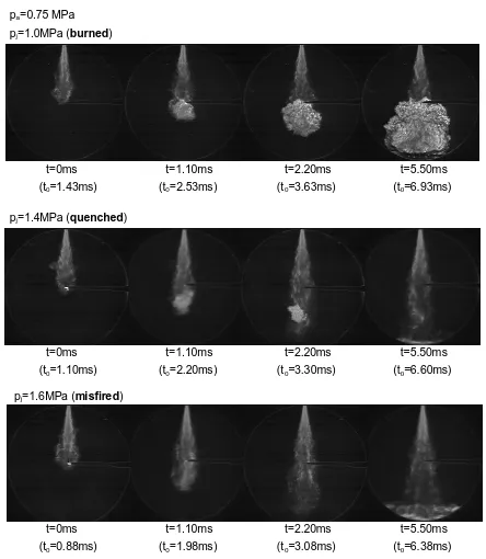
Figure 2.1 shows the experimental result done in a constant volume chamber. The images shown in the figure were captured using Schlieren photography technique by a high-speed digital video camera (Eastman Kodak, Ektapro HS4540) at a high-speed of 9000fps. The CNG fuel injector was installed in the upper part of the chamber, and an ignition point of a spark plug was set perpendicularly at the center of the observation window of 70mm in diameter. The ambient pressure was set at pa=0.75MPa and the injection pressures were
pj=1.0, 1.4, and 1.6MPa. The gas fuel injection period was constant at 10ms, and ignition was
Fig. 2-1 Schlieren images of flame development and quenching process of gas-jet direct-ignition
method
From the figure, at low injection pressure pj=1.0MPa, the gas-jet ignited, at pj=1.4MPa
the gas-jet quenched, and at pj=1.6MPa the gas-jet misfired. For low speed gas-jet with
pj=1.0MPa the flame started to develop immediately after ignition at the center of the
electrodes. The flame continued to develop downstream and the fuel mixture burned at the
pj=1.0MPa (burned)
pa=0.75 MPa
pj=1.4MPa (quenched)
pj=1.6MPa (misfired)
(t0=2.53ms)
t=1.10ms t=5.50ms (t0=6.93ms)
(t0=1.43ms)
t=0ms
(t0=3.63ms)
t=2.20ms
(t0=2.20ms)
t=1.10ms t=5.50ms (t0=6.60ms)
(t0=1.10ms)
t=0ms
(t0=3.30ms)
t=2.20ms
(t0=1.98ms)
t=1.10ms t=5.50ms
(t0=6.38ms)
(t0=0.88ms)
t=0ms
(t0=3.08ms)
bottom of the chamber. However, for gas-jet with pj=1.4MPa the initial flame kernel was
observed after ignition but it failed to developed. The flame kernel was quenched at the bottom part of the chamber. On the other hand, no visible flame kernel was observed for high speed gas-jet with pj=1.6MPa. It was considered as misfired.
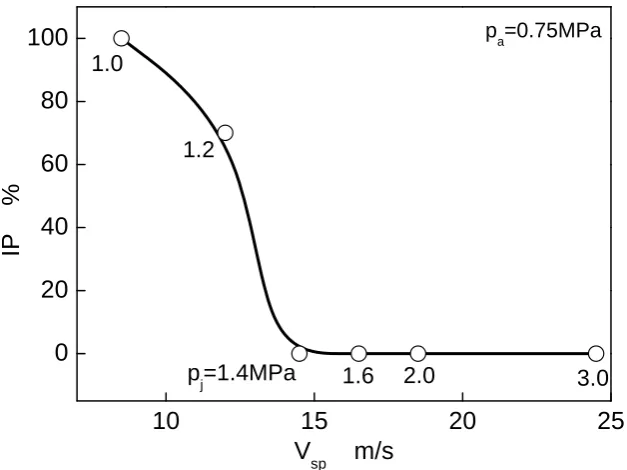
Figure 2-2 shows the relation of gas-jet stream speed Vsp near the ignition position with
[image:27.595.152.466.429.664.2]ignition probability IP. The ignition probability in this research is defined by 10 times or more tests; where 10% pressure rise from the ambient pressure at ignition timing is regarded as burned. It turns out that ignition probability is falling with the increase of gas-jet stream speed. In this particular study the gas-jet stream speed of more than 15 m/s had caused combustion failure by initial flame quenching or misfires. Thus to achieve stable combustion, it is necessary to control the gas-jet stream speed near the ignition position. It signifies that this particular parameter is very important when applying the gas-jet direct ignition method in a real engine.
Fig. 2-2 Ignitability of gas-jet direct-ignition with changed gas-jet velocity
10 15 20 25
0 20 40 60 80 100
3.0 2.0
1.6 p
j=1.4MPa
1.2 1.0
pa=0.75MPa
IP %
V
Next, the effectiveness of multi-stage injection for CNG combustion stabilization is explained. Figure 2-3 shows four ignition positions studied in a constant volume combustion chamber; (1) the STD ignition position which is at 35mm downstream of the injector outlet, (2) US which is 6mm downstream the gas injector nozzle but has a 5mm offset from the center of the nozzle axis, (3) UC without bluff body, which is 12mm downstream the gas injector nozzle, and (4) UC with bluff body, which has one of the electrodes that obstructs the downstream path of the gas-jet. Because of the 5mm off center, the US ignition position has the lowest gas-jet stream velocity compared with other ignition positions.
The fuel injection methods are single stage injection (Single injection) and multi-stage injection (Multiple injections) as shown in Fig. 2-4. The total injection time was 10ms for both single injection and multiple injections. For the single injection, the gas-jet was ignited at the time when the fuel jet stream first reaches at the STD or US ignition position. For the multiple injections the fuel was delivered in 3 pulses over the 10 ms total injection period. In the multiple injections, ignition at UC is performed after injecting small amount of fuel by the
first pulse injection. The first step is to create flame kernel at the time when gas-jet stream speed fell, and the further two-steps making it burn by supplying fuel in a fully grown-up flame.
Figure 2-5 shows the ignition probability IP of changing the injection method and an ignition position relative to the injection pressure pj. The ambient pressure was fixed at
0.75MPa. From the figure, also at any condition, if the injection pressure becomes high and
Fig. 2-3 Layout of gas injector and spark plug for gas-jet direct-ignition ignitability investigation
Fig. 2-4 Fuel delivery and ignition method for gas-jet direct-ignition ignitability investigation
Fig. 2-5 Effect of multiple-injection and plug position on ignitability of gas-jet direct-ignition
1 2 3 4 5
0 20 40 60 80 100 Multiple-inj. Injection Ignition Injection Ignition Single-inj. US STD UC w/o Bluff body UC with Bluff body pa=0.75 MPa
IP %
p
j MPa Inj. signal
2 1 1 1 7 ms
(tInj=10 ms) 1st. 2nd. Main-Inj.
(tInj=10 ms)
Ignition Ignition
(a) Single injection (b) Multiple injections
6 STD US UC Injector Plug UC
[image:29.595.150.465.495.743.2]2.2 Timing of Gas-jet Injection and Ignition
At present there are three types of fuel delivery and combustion method for CNG direct injection engines. Figure 2-6 shows the three methods for CNG injection and ignition [72]: (a) premixed-type ignition, (b) gas-jet ignition, and (c) gas-jet ignition with two-stage injection. For the premixed-type ignition, fuel is injected early at compression stroke. For the gas-jet ignition, fuel is injected near the ignition timing. For the two-stage injection, the first injection
timing, j1 and its duration, j1 are varied depending on the bilk equivalence ratio, and
engine performance. The second injection timing, j2 and injection duration j2 are the same
[image:30.595.210.394.341.695.2]as the gas-jet ignition.
Fig. 2-6 Timing chart for gas-jet injection and ignition θg=TDC
Injection Ignition
θj = -170
°
ATDC Δθjθg=TDC Injection
Ignition
θj1 θj2
Δθj1 Δθj2
θg=TDC
Injection Ignition
θj=-6°
Δθj
ATDC (a) Premixed-type ignition
(1) Premixed-type Ignition Method (Fig. 2-6(a))
Using premixed-type ignition, combustibility depends on the global equivalence ratio,
. The premixed-type ignition method injects the fuel early at compression stroke. The
purpose of early fuel injection is to create close to homogeneous mixture as possible before ignition. This type of delivery is most suitable for high load operation, i.e. stoichiometric equivalence ratio or higher. From previous work of [55, 73, 74] it is
known that the lean combustion operating limit for this type of fuel delivery is =0.6
to 0.8.
(2) Gas-jet Ignition Method (Fig. 2-6(b))
The combustibility using this method relies on local fuel-air mixture concentration near the ignition position. The gas-jet ignition method employs late injection timing technique which is very near to the ignition timing. The optimal injection timing is when the injected fuel just reaches the ignition point with low jet velocity to ensure ignitability, while at the same time creating enough combustible mixture to support flame core development. The ignitability of mixture using this method has been studied by several authors [60, 71, 75, 76]. According to Kidoguchi et al. [60] the ignitability of gas-jet ignition is ensured if the spray velocity hitting the ignition point is less than 16 m/s and the local mixture surrounding the spark position is near stoichiometric. Spray velocity higher than this value or the rich fuel distribution
locally near the ignition point, would result in flame quenches or misfires.
(3) The Gas-jet Ignition with Two-stage Injection Method (Fig. 2-6(c))
mixture ignition is ensured by gas-jet ignition. The flame development is dependent on the early fuel injection. The gas-jet ignition setting is usually fixed while the first injection timing and duration are changed to suit the desired mixture equivalence ratio.
2.3 Application of Gas-jet Ignition Method to a CNG Engine
A typical CNG engine can operate in range of equivalence ratio between 0.8 and 1.1, by using premixed ignition method. Problems such as ignitability, cyclic variation and high THC emission were common for combustion leaner than 0.8 equivalence ratio. The purpose of this study is to extend the stable lean operating range of the CNG engine by addressing such problems by applying the gas-jet ignition method and hydrogen addition method to control ignition, flame development and THC formation. This research is divided into five phases:
(1) Engine test using premixed ignition; where typical operation of CNG engine using direct injection premixed ignition method was investigated, and used as a benchmark.
(2) Gas-jet ignition optimization and engine test; where the gas-jet ignition technique was tested and optimized using the test engine and using spray Schlieren images captured in a constant volume chamber.
(3) Engine test using gas-jet ignition with two-stage injection; where the gas-jet ignition with two-stage injection was implemented to overcome the limited capability of
premixed ignition and the gas-jet ignition techniques at lean combustion. Effect of varying the first injection timing (while keeping the gas-jet ignition timing constant) on the test engine performance and emission was also investigated. Further combustion improvements study was also made using mixed fuel of CNG with hydrogen addition.
References
[1] T. S. Board, "Resource Efficiency Strategy 2009-2012," Technology Strategy Board, UK, 2009.
[2] D. Helm, "What next for EU energy policy?," Centre for European Reform, European Union, 2011.
[3] A. Petersen and K. Barysch, "Russia, China and the geopolitics of energy in Central Asia," Centre for European Reform, European Union, 2011.
[4] T. W. House, "Securing American Energy: Develop and Secure America's Energy Resources," Washington DC: http://www.whitehouse.gov/energy/securing-american-energy, 2011.
[5] S. Tanaka, "Japanese Automobile Industry and Automobile Industry Policy," Ministry of Economy, Trade and Industry, 2010.
[6] EIA, "International Energy Outlook 2009," US Energy Information Administration, DOE/EIA-0484(2009), 2009.
[7] F. J. Gavin, "The Gold Battles Within the Cold War: American Monetary Policy and the Defense of Europe, 1960-1963," Diplomatic History, vol. 26, 1, pp. 61-94, 2002. [8] R. Bulliet, P. K. Crossley, D. R. Headrick, S. Hirsch, L. L. Johnson, and D. Northrup,
"Chapter 31: The Cold War and Decolonization, 1945–1975," in The Earth and Its Peoples: A Global History, 3 ed: Houghton Mifflin, 2005.
[9] W. Moomaw, F. Yamba, M. Kamimoto, L. Maurice, J. Nyboer, K. Urama, and T.
Weir, "Introduction," in IPCC Special Report on Renewable Energy Sources and Climate Change Mitigation, O. Edenhofer, R. Pichs-Madruga, Y. Sokona, K. Seyboth,
P. Matschoss, S. Kadner, T. Zwickel, P. Eickemeier, G. Hansen, S. Schlömer, and C. v. Stechow, Eds.: Cambridge University Press, 2011.
[10] S. McAllister, J.-Y. Chen, and A. C. Fernandez-Pello, Fundamentals of Combustion Processes, 1st ed.: Springer, 2011.
[11] C. F. Corvalán, T. Kjellström, and K. R. Smith, "Health, Environment and Sustainable Development: Identifying Links and Indicators to Promote Action," Epidemiology, vol. 10, 5, pp. 656-660, 1999.
[13] M. Berglund, C. E. Bostroem, G. Bylin, L. Ewetz, L. Gustafsson, P. Moldeus, S. Norberg, G. Pershagen, and K. Victorin, "Health risk evaluation of nitrogen oxides," Scandinavian Journal of Work, Environment & Health, vol. 19, 2, pp. 1-8, 1993.
[14] J. H. Seinfeld and S. N. Pandis, "Chapter 2: Atmospheric Trace Constituents," in Atmospheric Chemistry and Physics: From Air Pollution to Climate Change, 2 ed:
John Wiley & Sons, 1998.
[15] G. E. Likens, C. T. Driscoll, and D. C. Buso, "Long-Term Effects of Acid Rain: Response and Recovery of a Forest Ecosystem," Science, vol. 272, 5259, pp. 244-246,
1996.
[16] R. B. Gupta, Hydrogen Fuel: Production, Transport, and Storage: CRC Press, 2008. [17] B. C. H. Steele, "Fuel-cell technology: Running on natural gas," in Nature. vol. 400:
Macmillan Magazines, 1999, pp. 619-621.
[18] P. Hoffmann, Tomorrow's Energy: Hydrogen, Fuel Cells, and the Prospects for a Cleaner Planet 1st Paperback ed.: The MIT Press, 2002.
[19] G. Holland and J. Provenzano, The Hydrogen Age: The: Empowering a Clean-Energy Future: Gibbs Smith, 2007.
[20] J. J. Romm, The Hype About Hydrogen: Fact and Fiction in the Race to Save the Climate, 1st ed.: Island Press, 2005.
[21] J. M. Ogden, "Hydrogen as an Energy Carrier: Outlook for 2010, 2030 and 2050," in The Pew Center on Global Climate Change and the National Commission on Energy
Policy, 2004.
[22] ClimateTechWiki, "Hydrogen Technologies,"
http://climatetechwiki.org/technology/hydrogen, 2006.
[23] J. A. Turner, "A Realizable Renewable Energy Future," Science, vol. 285, 5428, pp. 687-689, 1999.
[24] A. Züttel, "Introduction," in Hydrogen as a Future Energy Carrier, 1st ed, A. Züttel, A. Borgschulte, and L. Schlapbach, Eds.: Wiley-VCH, 2008.
[25] B. D. Solomona and A. Banerjee, "A global survey of hydrogen energy research, development and policy," Energy Policy, vol. 34, 11, pp. 781-792, 2006.
[26] C.-J. Winter, "Hydrogen Energy - Abundant, Efficient, Clean A Debate over the
[27] Roads2HyCom, "Timelines of Hydrogen and Fuel Cell Emerging Products,"
http://www.ika.rwth-aachen.de/r2h/index.php/Timelines_of_Hydrogen_and_Fuel_Cell_Emerging_Products,
2008.
[28] P. Corporation, "Worldwide Look at Reserves and Production," Oil & Gas, vol. 106, 48, pp. 22-23, 2008.
[29] EIA, "International Energy Module," US Energy Information Administration, DOE/EIA-0554(2010), 2010.
[30] M. Q. Wang and H. S. Huang, "A Full Fuel-Cycle Analysis of Energy and Emissions Impacts of Transportation Fuels Produced from Natural Gas," Argonne National Laboratory, ANL/ESD-40, 1999.
[31] K. Chandler, K. Walkowicz, and N. Clark, "United Parcel Service (UPS) CNG Truck Fleet: Final Results," US Department of Energy, 2002.
[32] A. Serchuk, "The Environmental Imperative for Renewable Energy: An Update," Renewable Energy Policy Project, USA, 2000.
[33] "Guidelines for Conversion of Diesel Buses to Compressed Natural Gas," in Economic and Social Commission for Asia and the Pacific New York: United Nations, 1993.
[34] C. G. Bauer and T. W. Forest, "Effect of hydrogen addition on the performance of methane-fueled vehicles. Part I: effect on S.I. engine performance," International Journal of Hydrogen Energy, vol. 26, pp. 55-70, 2001.
[35] L. M. Das, R. Gulati, and P. K. Gupta, "A comparative evaluation of the performance characteristics of a spark ignition engine using hydrogen and compressed natural gas as alternative fuels," International Journal of Hydrogen Energy, vol. 25, 7, pp. 83-93, 2000.
[36] F. Ma and Y. Wang, "Study on the extension of lean operation limit through hydrogen enrichment in a natural gas spark-ignition engine," International Journal of Hydrogen Energy, vol. 33, pp. 1416-1424, 2008.
[37] W. Peschka, E. A. Wilhelm, and U. Wilhelm, Liquid Hydrogen: Fuel of the Future: Springer-Verlag, 1992.
[38] R. L. Hoekstra, P. V. Blarigan, and N. Mulligan, "NOx Emissions and Efficiency of
[39] S. O. B. Shrestha and G. A. Karim, "Hydrogen as an additive to methane for spark ignition engine applications," International Journal of Hydrogen Energy, vol. 24, pp. 577-586, 1999.
[40] Z. Huang, J. Wang, B. Liu, K. Zeng, J. Yu, and D. Jiang, "Combustion Characteristics of a Direct-injection Engine Fueled with Natural Gas–Hydrogen Blends under
Different Ignition Timings," Journal of Fuel, vol. 86, 3, pp. 381-387, 2007. [41] M. Shioji, M. Kitazaki, A. Mohammadi, K. Kawasaki, and S. Eguchi, "Knock
Characteristics and Performance in an SI Engine With Hydrogen and Natural-Gas
Blended Fuels," SAE Technical Paper, 2004-01-1929, 2004.
[42] J. Wang, Z. Huang, Y. Fang, B. Liu, K. Zeng, H. Miao, and D. Jiang, "Combustion behaviors of a direct-injection engine operating on various fractions of natural gas– hydrogen blends," International Journal of Hydrogen Energy, vol. 32, pp. 3555-3564, 2007.
[43] K. Zeng, Z. Huang, B. Liu, L. Liu, D. Jiang, Y. Ren, and J. Wang, "Combustion Characteristics of a Direct-injection Natural Gas Engine under Various Fuel Injection Timings," Applied Thermal Engineering, vol. 26, pp. 806-813, 2006.
[44] S. O. Akansu, Z. Dulger, N. Kahraman, and T. N. Veziroglu, "Internal Combustion Engines Fueled by Natural Gas—Hydrogen Mixtures," International Journal of Hydrogen Energy, vol. 29, pp. 1527–1539, 2004.
[45] N. Kahraman, B. Ceper, S. O. Akansu, and K. Aydin, "Investigation of combustion characteristics and emissions in a spark-ignition engine fuelled with natural gas– hydrogen blends," International Journal of Hydrogen Energy, vol. 34, pp. 1026-1034, 2009.
[46] M. Bysveen, "Engine characteristics of emissions and performance using mixtures of natural gas and hydrogen," Energy, vol. 32, pp. 482-489, 2007.
[47] T. Suga, T. Muraishi, T. Brachmann, and F. Yatabe, " Potential of a Natural Gas Vehicle as EEV," SAE Technical Paper, 2000-01-1863, 2000.
[48] R. Tilagone, G. Monnier, A. Chaouche, Y. Baguelin, and S. De Chauveron,
"Development of a high efficiency, low emission SI-CNG bus engine," SAE Technical Paper, 961080, 1996.
[50] NGV-Global, "Natural Gas Vehicle Statistics," International Association for Natural Gas Vehicles: http://www.iangv.org/tools-resources/statistics.html, 2010.
[51] P. Boisen, "Worldwide NGV Shares in Total Vehicle Market," NGVA Europe, 2012. [52] P. Boisen, "NGVs and Fuel Consumption Worldwide," NGVA Europe, 2012.
[53] H. M. Cho and B. Q. He, "Spark ignition natural gas engines—A review," Energy Conversion and Management, vol. 48, pp. 608–618, 2006.
[54] T. Kato, K. Saeki, H. Nishide, and T. Yamada, "Development of CNG fueled engine with lean burn for small size commercial van," JSAE Trans., vol. 22, 36, pp. 5-8, 2001.
[55] P. Corbo, M. Gambino, S. Iannaccone, and A. Unich, "Comparison Between Lean-Burn and Stoichiometric Technologies for CNG Heavy-Duty Engines," SAE Technical Paper, 950057, 1995.
[56] L. Ben, N. Raud-Ducros, R. Truquet, and G. Charnay, "Influence of Air/Fuel Ratio on Cyclic Variation and Exhaust Emission in Natural Gas SI Engine," SAE Technical Paper, 1999-01-2901, 1999.
[57] Z. Huang, S. Shiga, T. Ueda, H. Nakamura, T. Ishima, T. Obokata, M. Tsue, and M. Kono, "Combustion Characteristics of Natural-gas Direct-injection Combustion under Various Fuel Injection Timings," Proc. of the IMechE, vol. 217, 5, pp. 393-401, 2003. [58] J. B. Heywood, Internal Combustion Engine Fundamentals: McGraw-Hill, 1988. [59] A. E. Hassaneen, K. S. Varde, A. H. Bawady, and A. A. Morgan, "A study of the
flame development and rapid burn durations in a lean-burn fuel injected natural gas S.I. engine," SAE Technical Paper, 981384, 1998.
[60] Y. Kidoguchi, S. Masaaki, U. Hiromitsu, and K. Miwa, "A Fundamental Study on Improvement of Ignitability and Combustion Stability of CNG Jet (in Japanese)," Trans. of JSAE, vol. 36, 1, pp. 15-20, 2005.
[61] Y. Goto, "Mixture Formation and Ignition in a Direct Injection Natural Gas Engine," JSME Int J Ser B (Jpn Soc Mech Eng), vol. 42, 2, pp. 268-274, 1999.
[62] D. S. K. Ting and M. D. Checkel, "The effects of turbulence on spark-ignited, ultra lean, premixed methane–air flame growth in a combustion chamber," SAE Technical Paper, 952410, 1995.
[63] A. Das and H. C. Watson, "Development of a natural gas spark ignition engine for
[64] B. Johansson and K. Olsson, "Combustion chambers for natural gas SI engines part I: Fluid flow and combustion," SAE Technical Paper, 950469, 1995.
[65] T. Huang, J. Jin, C. Liao, and L. Yao, "Comparative Tests and Analysis of Ignition Energy and Ionic State in Lean Combustion," in 9th International Conference on Electronic Measurement & Instruments, 2009. ICEMI '09. vol. 2 Beijing, 2009, pp.
168-173.
[66] R. D. Nine, N. N. Clark, B. E. Mace, and L. El Gazzar, "Hydrocarbon Speciation of a Lean Burn Spark Ignited Engine," SAE Technical Paper, 972971, 1997.
[67] R. J. Amorim, J. G. C. Baeta, R. M. Valle, J. E. M. Barros, and R. D. B. d. Carvalho, "The Influence of Different Compression Ratios on the Performance of an
CNG-Fuelled Flex Internal Combustion Engine," SAE Technical Paper, 2005-01-4141, 2005. [68] L. Andreassi, S. Cordiner, V. Rocco, M. Gambino, and S. Iannaccone, "Analysis of
Combustion Instability Phenomena in a CNG Fueled Heavy-Duty Turbocharged Engine," SAE Technical Paper, 2001-01-1907, 2001.
[69] J. Getzlaff, J. Pape, C. Gruenig, D. Kuhnert, and R. Latsch, "Investigations on Pre-Chamber Spark Plug with Pilot Injection," SAE Technical Paper, 2007-01-0479, 2007. [70] K. Kamoto, D. Ikeda, Y. Kidoguchi, A. Mohammadi, and K. Miwa, "A Study on
Combustion Control of Hydrogen and CNG Intermittent Gas Jet (in Japanese)," in Annual Conference of Japan Society of Mechanical Engineers, 2001.
[71] Y. Kidoguchi, K. Kamoto, H. Umano, A. Mohammadi, and K. Miwa, "Optimization of Ignition Condition for the Ignition and Combustion Control of Hydrogen and CNG Gas Jet (in Japanese)," Nippon Kikai Gakkai, Jidosha Gijutsukai Nainen Kikan Shinpojiumu Koen Ronbunshu, vol. 17, pp. 273-278, 2002.
[72] Y. Kidoguchi, S. Nakao, Y. Oka, and T. Yatsufusa, "A Study on Lean Combustion in a Direct Injection CNG Engine using Injection Control (in Japanese)," Trans. of JSAE, vol. 41, 4, pp. 859-864, 2010.
[73] X. Mao, D. Wang, W. Xiao, Z. Liu, J. Wang, and H. Tang, "Lean Limit and Emissions Improvement for a Spark-Ignited Natural Gas Engine Using a Generalized Predictive Control (GPC)-Based Air/Fuel Ratio Controller," Energy Fuels, vol. 23, pp. 6026– 6032, 2009.
[75] M. Sato, H. Umano, Y. Kidoguchi, and K. Miwa, "Improvement of Ignitability and Combustion Stability of CNG Intermittent Gas Jet (in Japanese)," Nihon Kikai Gakkai Nenji Taikai Koen Ronbunshu, vol. 3, pp. 117-118, 2003.
[76] Y. Kidoguchi, Y. Nakamura, N. Nakajima, Y. Fukui, and K. Miwa, "Control of Injection and Ignition to Improve Ignitability of CNG Jet (in Japanese)," Trans. of JSME, vol. 74, 743, pp. 1655-1661, 2008.
[77] K. Miwa, Y. Kidoguchi, and A. Mohammadi, "A Study on a New Combustion Cycle with a New Internal Combustion Engine with Rhombic Link Z-crank Mechanism (in
Japanese)," Trans. of JSAE, vol. 33, 2, pp. 19-24, 2002.
[78] M. Kubota, "Grind Mechanism for Swash Plate and Optimum Cylinder Layout (in Japanese)," Trans. of JSME, vol. 17, 59, pp. 137-143, 1951.
[79] Y. Matsuura, A. Misawa, Y. Kidoguchi, and K. Miwa, "Development of a Quasi Constant-Volume Combustion Type Engine Employing Z-Crankshaft Mechanism (in Japanese)," Trans.of JSDE, vol. 40, 6, pp. 304-310, 2005.
![Fig. 1-1 History and projections of world oil price [6]](https://thumb-us.123doks.com/thumbv2/123dok_us/8777178.902107/9.595.169.471.534.745/fig-history-projections-world-oil-price.webp)
![Fig. 1-2 Global CO2 emission from fossil fuel burning from 1850 to 2007 [9]. The unit is in Gigatonne](https://thumb-us.123doks.com/thumbv2/123dok_us/8777178.902107/10.595.91.535.387.583/fig-global-emission-fossil-fuel-burning-unit-gigatonne.webp)
![Fig. 1-3 Hydrogen production pathways [22, 23]](https://thumb-us.123doks.com/thumbv2/123dok_us/8777178.902107/12.595.105.516.105.283/fig-hydrogen-production-pathways.webp)

![Table 1-2 Properties of methane and hydrogen [34-37]](https://thumb-us.123doks.com/thumbv2/123dok_us/8777178.902107/15.595.164.473.122.460/table-properties-methane-hydrogen.webp)
![Fig. 1-5 Global primary energy supply in 2008 [9]](https://thumb-us.123doks.com/thumbv2/123dok_us/8777178.902107/17.595.90.540.411.663/fig-global-primary-energy-supply.webp)
![Table 1-4 Top ten countries with largest NGVs and their fuel consumption worldwide in 2012 [52]](https://thumb-us.123doks.com/thumbv2/123dok_us/8777178.902107/20.595.112.515.144.358/table-countries-largest-ngvs-fuel-consumption-worldwide.webp)