Real-Time 3D Reconstruction Using a Kinect Sensor
Claudia Raluca Popescu
*, Adrian Lungu
Politehnica University of Bucharest, Bucharest, 060042, Romania *Corresponding Author: [email protected]
Copyright © 2014 Horizon Research Publishing All rights reserved.
Abstract
Nowadays, in the robotics industry, the point cloud processing gets more and more well-known due to the launching of Microsoft Kinect device in 2011. This paper aims to compare the methods for 3D reconstruction using a Kinect sensor and to rebuild a detailed model from an indoor scene in order to use it in a CAD application. The acquisition system allows the user to rotate around the target area and see a continuously updated 3D model of the desired object. For creating the final model, different viewpoints must be acquired and fused together in a single representation.Keywords
Point Cloud, Depth Camera, 3D Model Acquisition, Surface Reconstruction, Tracking, Real-Time Modeling1. Introduction
Tridimensional perception is more and more significant in robotics industry as well as in other fields, due to 3D sensing hardware such as Kinect device or Structure sensor from Occipital – the first 3D sensor for mobile devices -, which was recently launched [7].
The Kinect sensor was developed by Microsoft in cooperation with PrimeSense. Kinect is a structured light laser scanner that generates real-time depth maps. The device obtains a colored 3D point cloud also called RGB-D image, with more than 300.000 points at a frame rate of 30Hz.
The Kinect sensor consists of 3 different systems that are working together on the PrimeSense System-on-a-Chip (SoC) Carmine (PS1080) or next generation SoC Capri (PS1200) that execute sophisticated parallel computational algorithms in order to produce a VGA depth image with the resolution of 640x480 pixels out of the raw distance values which are sampled at a resolution of 1600x1200 pixels.
The depth sensor consists of an infrared laser projector combined with a monochrome CMOS sensor, which captures video data in 3D under any ambient light conditions.
This 3D scanner system called Light Coding is basically based on “Structured Light” method (Figure 1). The
[image:1.595.329.538.271.562.2]technology consists on the propagation in the scene of a codified light that is very close to infra-red (invisible for the human eye).
Figure 1. PrimeSense Light Coding Technology [2]
2. Materials and Methods
This section presents two different approaches in tridimensional reconstruction: Microsoft KinectFusion and KinFu.
Microsoft KinectFusion is a technique that uses the Kinect sensor to reconstruct the 3D scenes in real-time. The system reconstructs a single dense surface model by integrating the depth data over time from multiple viewpoints [9].
2.1. Microsoft KinectFusion
MS KinectFusion is an algorithm developed in 2011 by Microsoft Research. The algorithm allows a user to pick up a standard Kinect sensor and move inside a room for reconstructing a high-quality and geometrically accurate 3D model of the physical scene. The algorithm tracks in a continuous manner the 6 degrees of freedom pose of the sensor (location and orientation) and combines in real time the depth data from the camera in a unique 3D model [1].
In order to achieve real-time results, the Kinect Fusion algorithm is executed almost exclusively on graphics card using highly parallel GPGPU techniques (CUDA).
First, the algorithm acquires the data from the camera and processes it. After that, the sensor’s position in space is estimated and the algorithm fills a 3D volume with truncated signed distance function (TSDF) values that is updated in each single frame. For each voxel, the TSDF function determinates the distance to the nearest surface along the viewing direction. Finally, a ray-casting algorithm is used to extract the surfaces out of the volume.
The input data of the algorithm is represented by a real-time sequence of depth maps returned by the sensor. Due to the fact that the algorithm uses only the depth maps and doesn’t need color information, it allows running even in darkness.
Tracking and surface reconstruction is implemented in four main stages from raw depth map to rendered view of 3D physical scene:
surface extraction: in this step 3D surface positions and normal are computed;
alignment: in this step the sensor’s position and orientation are estimated;
volumetric integration: in this step a 3D volume with surface information is filled;
ray-casting: the surface positions are computed and are used in rending process.
2.1.1. Surface extraction
The first step is to convert the live depth map acquired from Kinect sensor into a 3D point cloud with vertex and normal data. To do that, first of all, the raw depth map is preprocessed by applying a bilateral filter so that the noise is reduced and small holes are covered.
A calibration matrix is internally stored by Kinect device. This matrix matches depth pixels to 3D vertex in the camera coordinate space. By using the vertex map, the normal of each point is generated by calculating the cross product of two vertices – the neighboring projected points: the one above the chosen point and the other one to its right.
ni(u) = (vi(x+1,y)- vi(x,y)) × (vi(x,y+1)- vi(x,y)) (1) Based on these two maps, a multi scale resolution pyramid of height L = 3 is built by sub-sampling both the vertex and normal map using an average smoothing filter. The result of this stage is a point cloud with vertex and normal information for each point at three different levels of detail.
2.1.2. Alignment
In this step camera’s position and orientation are estimated in world space by computing the 6 degrees-of-freedom (DOF) of the sensor pose. The algorithm that is used for obtaining the 6DOF transform is ICP (Interactive Closest Point). The algorithm takes the data that are measured in the scene – composed from a vertex map and a normal map of current frame (vi, ni) and the result of the surface prediction in the
previous frame (vi-1, ni-1). The two point clouds are compared
one with the other and the corresponding points are selected in order to determinate an estimated frame-to-frame transform. This will be applied to the previous frame’s data.
After a match is found, ICP algorithm calculates the error between the two points in a match with a point-to-plane metric.
Each ICP iteration has to minimize this error defined as the sum of squared distances between each point in the current frame and the tangent plane at its corresponding point in the previous frame.
As a result, a 6-dimensional transformation matrix is obtained (2) which contains the 6 DOF of the sensor motion (3 rotation angles and 3 translations).
T = (α, β, γ, tx, ty, tz)T (2) Once the alignment transform is found, the current pose of the sensor is estimated.
2.1.3. Volumetric Integration
The third step in KinectFusion algorithm is the integration (or fusing) of the depth data into a single volumetric representation of the scene. It is performed by filling a tridimensional volume with surface data using the raw depth map.
First of all, the depth map values will be converted in 3D world space coordinates provided from the current camera pose that was computed in the previous step.
[image:2.595.316.548.577.680.2]For each voxel of the tridimensional space, a signed distance is computed and truncated at µ value which forms a TSDF (truncated signed distance function) over the scene, so that every voxel value shows its distance to the next surface point in view direction of the sensor.
Figure 2. Truncated signed distance function (TSDF) [4]
TSDF function (Figure 2) basically extracts the surface of the objects in the scene and assigns:
- positive numbers to those pixels that are outside the surface, increasing the further they are from it; - zero value to pixels that are on the surface.
The resulting TSDF is used to reconstruct the surface of the current, refined model. To do so, ray casting is applied. 2.1.4. Ray-casting
The last step in KinectFusion algorithm is surface reconstruction that is executed using ray-casting.
Ray casting is done from a given starting position and direction of the ray (that is calculated in step 2) traversing voxels along the ray and extracting the position of the desired surface by intersecting the zero level set of TSDF (that is already determined in step 3).
- A positive-to-negative zero-crossing means a front facing surface.
- A negative-to-positive zero-crossing means a back facing surface.
[image:3.595.60.297.323.440.2]The final result is a tridimensional representation of the acquired scene (Figure 3).
Figure 3. The scene reconstructed with KinectFusion
2.1.5. Limitations
Although the algorithm allows the reconstruction of an entire room due to its assumptions and heavy parallelization, it still faces to some limitations:
- it requires a powerful GPU to work and a high computational power;
- for a stable tracking, scenes must have sufficient depth variation in view and the movement has to be small and slow (both in translation and rotation); - the motion of the sensor must be supervised, even at
a high frame-rate, because ICP alignment may not converge to a right match; it’s important not to have a fast or jerkily movement;
- some objects may not appear in the depth image as they reflect or absorb too much IR light; they have to be scanned from different angles, especially perpendicular to the surface [9].
Nevertheless, KinectFusion algorithm has a high degree of robustness to the presence of dynamic objects appeared in the scene. The objects will be removed from the final point cloud model.
2.2. KinFu
KinFu is an open-source version of Microsoft KinectFusion algorithm and is part of Point Cloud Library (PCL). Point Cloud Library is a stand-alone, large-scale, open project for 2D/3D image and point cloud processing [5]. Another methods and implementations for efficient processing of large scale 3D points clouds are 3DTK – The 3D Toolkit and Las Vegas Reconstruction Toolkit.
Compared to KinectFusion approach, KinFu introduces few improvements, which are listed below:
- despite KinectFusion, that can work only with a Kinect device, KinFu can work with any OpenNI (Natural Interaction) compatible depth sensor;
- the color information can be shuffled in the reconstructed surface;
- KinFu can be used to reconstruct large scenes – such as full rooms (KinFu large-scale version) providing a point cloud representation of the entire scene; - the surface estimation step is done using eigen-value
estimation in contrast with simple cross-vector calculation;
- in the last step, rendering is done using a marching cubes algorithm instead of ray-casting [10].
The PCL cross platform is split into a collection of smaller code libraries that can be compiled separately. The library contains state-of-the-art algorithms for: filtering, feature estimation, surface reconstruction, registration, model fitting and segmentation [8]. The algorithms that are included in the implementation of KinFu are:
- libpcl_io: I/O operations (writing to/ reading from Point Cloud Data – PCD and BAG files);
- libpcl_filters: point cloud data filters (down-sampling, outlier removal, indices extraction, projections, etc.) - libpcl_surface: surface reconstruction techniques
(meshing, convex hulls, moving least squares, etc.) - libpcl_features: many 3D features (normals and
curvatures, boundary points, moment invariants, principal curvatures, Point Feature Histograms (PFH), Fast PFH, etc.)
- libpcl_segmentation: segmentation operations (cluster extraction, sample consensus model fitting, polygonal prism extraction, etc.)
- libpcl_registration: point cloud registration methods (Iterative Closest Point – ICP, non-linear optimizations)
- libpcl_range_image: range image class with specialized methods.
The KinFu algorithm is implemented in three steps: filtering: the filtering is done using a voxel grid filter;
the number of points in the cloud is reduced for future calculation;
alignment: in this step, the point clouds are aligned in order to be unified, and so to create the desired object;
2.2.1. Filtering
First, in this step, the number of points in the point cloud is reduced. This operation is named down-sampling and is done using a voxelized grid approach. A 3D voxel grid (this means a set of 3D small boxes in space) will be created over the input point cloud data. After that, for each voxel, all the points will be approximated with their centroid.
In order to discard the points outside a chosen 3D box, another filtering is implemented using a crop-box filter, which is a high pass through filter on 3 spatial dimensions.
Because the floor is still present in the point cloud after applying the voxel-grid and the crop-box filters, a segmentation of the cloud is performed for eliminating it. Simple plane segmentation is implemented, this means finding all the points inside the point cloud that support a plane model. Due to its simplicity, a Random Sample Consensus (RANSAC) method is applied. After finding the points that define the plane, they are removed and so a cloud representation of the desired cloud is obtained.
The last thing to do in this stage is to remove the noise from the obtained cloud applying a radius outlier removal filter. The filter removes all indices from the cloud that don’t have at least some number of neighbors with a certain range. 2.2.2. Alignment
The next step in KinFu algorithm is the alignment of the point clouds, so that they can be merged together resulting the final desired object.
To do this, the Sampled Consensus Initial Alignment algorithm (SAC-IA) is used. A set of points is random selected from the input point cloud data and a set of closest matches is obtained. Using these metrics and point-to-point error metrics, a transform matrix is estimated. This procedure is repeated a number of times and the best results are stored.
Compared with the Interactive Closest Point method, that was used in Kinect Fusion algorithm, Sampled Consensus Initial Alignment algorithm is less accurate but more robust for large translations and rotations.
2.2.3. Reconstruction
In this step, the conversion of the point cloud into a uniform mesh is done.
A greedy surface triangulation algorithm is implemented. It obtains a triangle mesh by projecting the local neighborhoods of a point along the point’s normal and connecting unconnected points.
Another possibility is to use a ray-casting method similar to the one used in Kinect Fusion algorithm.
3. Results
3.1. Problems Encountered
As in many applications, difficulties have encountered
during the development and running of the algorithm. For example, one of them was the recognition of dependencies made by the compiler for fixing up the PCL library. The modules compilation proved to be difficult according to the operating system and also to the compiler version. PCL v1.7.0 is running only using MS Visual Studio 2010 and Windows 8 OS. After a successful compilation, we have to remove some modules (that were unimportant for the project) for improving the performance.
Also, we have to modify CMake files for allowing few modules to recognize in a good manner all the dependencies made by the compiler.
In addition, we have also incurred the unstable version of PCL library. Although the KinFu implementation is available in this moment, in some cases it can’t treat in a successful manner the memory allocation. So, all the acquired data from the scene can be lost.
Another big issue is the lack of optimizations. When using a NVIDIA GeForce GTX 650 GPU with 1024MB memory, because we couldn’t be able to view a volumetric model of 2m3 size. The lack of optimization leads to the exportation of models that contains a huge amount of data points and polygons (million scale) and are hardly processed.
In addition, there were some incomplete models, the depth measurements often fluctuate and depth maps contain numerous holes where no reading data were obtained. For some complex models, the alignment step was impossible to be implemented. Due to the low accuracy of Kinect sensor (640x480 pixels), using a plant with thin leaves as a model, the alignment process was unsuccessful because all the details were overlapped. So, this model couldn’t be scanned.
3.2. Scanning the Model
After implementing the algorithm, a frame rate of 8-10 fps was obtained. Compared with the requirements of KinectFusion, it’s a low rate, but, fortunately, KinFu approach permitted it for model scanning. The total processing time was 23 minutes. The final point cloud at a 0.5 mm resolution contains approximately 4.5 million points and the resulted mesh 1.5 million polygons.
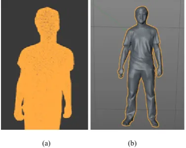
For processing the enormous amount of data, large-scale 3D point clouds processing is required. The resulting cloud doesn’t present noise and the floor plane has been segmented out, as well as all the other objects that were present in the scene (Figure 4).
Because the number of polygons was real huge, we applied a filter over the mesh. So, in the end, we counted 197.112 polygons and 109.527 points.
The final mesh was obtained after a manual processing in Cinema4D and 3D Studio Max to merge the parts from the model and to export it in .SDL format (Standard Tessellation Language) that is used in 3D scanners.
(a) (b)
Figure 4. (a) Final point cloud; (b) Final mesh
Figure 5. The final printed model
4. Conclusion
This paper presented two approaches of 3D reconstruction that can be made in a low-cost way using a Kinect sensor and a 3D printer.
The first one allows 3D reconstruction of a desired model and has the advantage of robustness to the presence of dynamic objects appeared in the scene. Some issues that have to be considered in using KinectFusion algorithm:
- the sensor must not be moved too fast or jerkily; - the device works even in completely darkness; - if some objects absorb or reflect too much IR light,
they may not appear in the depth image; for a correct reconstruction, it is necessary to scan them from different angles;
- for improving a problematic tracking, clutter can be added at different depths to scenes.
The second application - KinFu - has some advantages that are listed below:
- KinFu can work with any OpenNI compatible depth
sensor;
- the color information can be combined in the reconstructed surface;
- KinFu can provide a point cloud representation of the entire scene;
- the surface estimation step is done using eigen-value estimation in contrast with simple cross-vector calculation;
- in the alignment step, SAC-IA algorithm is used; compared with the ICP method, that was used in KinectFusion, this method is less accurate but more robust for large translations and rotations;
- in the reconstruction step, rendering is done using a marching cubes algorithm instead of ray-casting. Improvements can be made to the implemented the algorithms, such as: taking an indefinite number of clouds as input and merge them in a good manner to reconstruct the desired object, finding a method to reconstruct objects that are symmetric, etc.
REFERENCES
[1] S. Izadi et al. KinectFusion: Real-time 3D Reconstruction and Interaction Using a Moving Depth Camera, 24th ACM Symposium on User Interface Software and Technology, Santa Barbara, USA, October 16-19, 2011.
[2] http://www.primesense.com/solutions
[3] R. A. Newcombe et al., KinectFusion: Real-time Dense Surface Mapping and Tracking. In 10th IEEE International Symposium - Mixed and Augmented Reality (ISMAR), Basel, Switzerland, October 26-29, 2011.
[4] http://www.ifp.uni-stuttgart.de/lehre/diplomarbeiten/korcz/ [5] http://www.pointclouds.org/
[6] http://www.cs.ubc.ca/research/flann/
[7] http://www.kickstarter.com/projects/occipital/structure-senso r-capture-the-world-in-3d
[8] Radu Bogdan Rusu, Steve Cousins: 3D is here: Point Cloud Library (PCL), IEEE International Conference on Robotics and Automation (ICRA), Shanghai, China, May 9-13, 2011 [9] http://msdn.microsoft.com/
[image:5.595.79.280.254.365.2]![Figure 1. PrimeSense Light Coding Technology [2]](https://thumb-us.123doks.com/thumbv2/123dok_us/8783787.905681/1.595.329.538.271.562/figure-primesense-light-coding-technology.webp)
![Figure 2. Truncated signed distance function (TSDF) [4]](https://thumb-us.123doks.com/thumbv2/123dok_us/8783787.905681/2.595.316.548.577.680/figure-truncated-signed-distance-function-tsdf.webp)