5
III
March 2017
Technology (IJRASET)
A Study on Islanded and Parallel Operation of
Inverters in a Microgrid Using Droop Control
Strategy
Boni Sirisha1, G. Anitha2
1,2
Electrical and Electronics Engineering Department, Dadi Institute of Engineering and Technology
Abstract: Microgrids (MG) have gained major importance in the recent years, where much attention is given to the control of microgrid. In this context, this paper presents the droop control strategy in an islanded microgrid. Initially, the MG is operated in grid connected mode, where it is later switched to autonomous operation. The droop control technique is used to control the voltage and frequency under varying load conditions. Further, to realize the effectiveness of the control method, a system with parallel inverters is designed to share the load equally among the inverters. The model of the microgrid is designed and implemented in MATLAB/Simulink enivironment. Finally, the simulation results shows the effectiveness of the droop control in controlling the frequency, as well as equal load sharing is realized when inverters are operated in parallel.
Keywords: Distributed Generation, Droop Control, Frequency, Microgrid, Power Sharing, Renewable Energy Systems
I. INTRODUCTION
The distributed generation (DG) has gained much importance in the recent years with the increasing demand of energy, fast depletion of conventional energy resources and an increased concern of environmental changes. However, the operation of such DGs is challenging to provide efficient control mechanism with an objective to meet the power quality standards. In this context the microgrid concept has emerged in the recent years.
Microgrids (MG) are small power grids comprising of single or multiple distributed generations, loads, power electronics converters, energy storage systems and telecommunications. The flexible control of multiple DGs strengthen its reliability and power quality, in the meantime eliminate the impact of unstable power supply to the grids. Furthermore, with the improvement of the control capabilities and operational features of microgrids brings environmental and economic benefits.
The introduction of microgrids improves power quality, reduces transmission line congestion. The main goals is to ensure stable and efficient operation are frequency and voltage regulation, power control, synchronization, energy management, and economic optimization [1]-[3]. The various control approaches can broadly be classified into two groups: (i) wired or with communication channel and (ii) wireless or without communication channel. Wired control approaches include master-slave control, average current sharing control, central type control, and circular chain control [4]-[6] to achieve the rigid control on the voltage/current for load sharing. However, due to the long communication lines between the distantly placed DGs, such wired control approaches face the issues of stability, reliability, complexity, higher cost and interference by high frequency signals. Wireless control for among DGs mainly involves the principle of droop control [7]. Therefore, the droop control, which mimics the behavior of the synchronous generators [8]-[13], has been introduced to enable inverters to operate without any communication mechanism. The real or active power (P) and reactive power (Q) outputs of the DGs are regulated by controlling the frequency and voltage of the inverter, respectively. The control approach is thus based on P-ω and Q-V relationships. As the communication lines are absent in this droop control approach, the output voltage references for the DGs are produced by the inverters themselves and hence, chance of interference by noise or high frequency external signals is less.
A typical microgrid usually has two kinds of operation modes: 1) autonomous operation mode; and 2) grid-connected operation mode [14]–[16]. Without the support from the main grid, the control of an autonomous operation of MG is often more complex than the grid-connected one. When in islanded mode, a control mechanism is required for its efficient operation. Thus, based on the relationship between active power and frequency, reactive power and voltage, inverters can control the output. In this context, this paper focus on the design and implementation of the droop control method in grid and islanded mode of operation. Further this paper also focus on realization of load sharing among parallel inverters in a microgrid.
Technology (IJRASET)
design of the parallel operation of inverters in the microgrid to realize the load sharing using the droop control method. Whereas, the Section-3 presents the simulation results and discussion. Finally, the concluding remarks are provided in Section-4.
II. STRUCTUREOFTHEMICROGRIDANDOPERATION Three phase inverter
LC Filter Line impedance
T1 T3 T5
T4 T6 T2
+
_ DG Unit
Gate driving circuit
PWM
[image:3.612.80.516.113.325.2]Grid
Fig. 1 Structure of the Microgrid
The Fig. 1 shows the structure of the microgrid. It consists of a DG which can be fuel cells, PV, wind turbines or energy storage system, etc. In Fig. 1, the DG is connected to voltage source inverter (VSI) which is controlled by pulse width modulation (PWM). VSI converts DC voltage to AC voltage. The network is connected with LC filters and loads. The Fig. 1 also shows a grid with a switch to realize grid connected and islanded mode of operation.
abc dq
Power calculations
Voltage and Current controller
Droop Control Voltage
formation
abc dq
abc
dq abc
dq
PWM
Three phase inverter
LC Filter Line impedance
T1 T3 T5
T4 T6 T2
+
_
Load
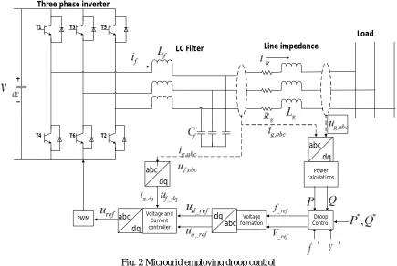
Fig. 2 Microgrid employing droop control
[image:3.612.89.524.406.698.2]Technology (IJRASET)
operation. The active power Pi, reactive power Qiand apparent power Sisupplied by the inverter to the bus/load can be expressed as,
Sin
i
EV
P
X
(1)2
Cos
i
EV
V
Q
X
(2)i i i
S
P
Q
(3)Where, X is the output reactance of an inverter, Φ is the phase angle between the output voltage of the inverter and the voltage of the common bus, E and V are the amplitude of the output voltage of the inverter and the common bus, respectively.
From (1) and (2), it is evident that the active power Pi is predominately dependent on the power angle Φ, while the reactive power
Qi mostly depends on the output voltage amplitude E. Stated differently; Pi can be controlled by adjusting the power angle Φ and
Qi can be controlled by regulating voltage E. However, in a stand-alone system, the frequency is used instead of the power angle or phase angle to control the active power flow. In other words, they employ Pi-ω (active power–frequency) droop in place of Pi –Φ
droop. Thus, by regulating the real and reactive power flows through a power system, the voltage and frequency can be determined. Consequently, most of the wireless-control uses the droop method. The equations representing these droop relation are expressed as,
0
m P
(
P
0)
(4)0
(
0)
E
E
n Q Q
(5)where ω is operating frequency of the inverter, ω0 is the frequency set point, m is the frequency droop coefficient, P is the real
power of the inverter, P0is the real power set point, E0 is the voltage set point, n is the voltage droop coefficient, and Q0is the reactive power set point.
Active power frequency
[image:4.612.164.463.413.534.2]Reactive power voltage
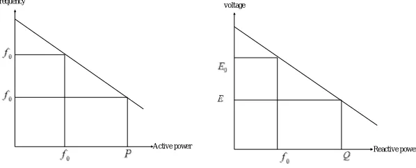
Fig. 3 Droop Characteristics a) P characteristic, b) Q-E characteristic
The Fig. 3 shows the typical droop characteristics. With reference Fig. 3, if frequency f0 decreases to f, then there is an increase in
power output of the generating unit from P0 to P. The decrease in frequency signifies an increase in load, which necessitates the
need for more active power. Multiple parallel units with the same droop characteristic can respond to the fall in frequency by increasing their active power outputs simultaneously. The increase in active power output will counteract the reduction in frequency and the units will settle at active power outputs and frequency at a steady-state point on the droop characteristic. The droop characteristic therefore allows multiple units to share load without the units fighting each other to control the load.
Technology (IJRASET)
shows the implementation of the power loop controller which contains droop control and voltage formation block.
3
2
d d q qP
v i
v i
(6)
3
2
q d d q [image:5.612.85.527.101.446.2]Q
v i
v i
(7)Fig. 4 Power Calculation
∠ ∠( −2 3)
∠( + 2 3)
∫ 2 1 1 abc dq Droop Control Voltage Formation _ _ ∗ ∗ ∗ ∗ + + + + - - - -
Fig. 5 Power Loop Controller
Now
andE
from (4) and (5) respectively will be used to generate a tracking signal for inner control loops.ref ref
dt
(8)ref ref
v
E sin
(9)Where
v
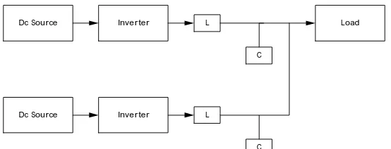
ref is a reference signal for voltage and current control loop. The inner control loop consists of current controller and voltage controller. The voltage controller uses PI controller to generate the required reference signals. The generated reference signals are used to generate the required PWM pulses. The designed microgrid structure with droop control method is implemented to realize the P and QE control.Further, the structure of microgrid shown in Fig. 1 is extended to implement the droop control method to realize the load sharing in parallel operation of DGs. The structure of the parallel DGs with parallel inverters is shown in Fig. 6.
Inverter
Dc Source L
C
Load
Inverter
Dc Source L
C
[image:5.612.143.471.604.702.2]Technology (IJRASET)
The Fig. 6 shows, two DG’s connected in parallel sharing a common load. To realize the important aspect of load sharing of parallel inverters in a microgrid with multiple DG’s, the droop control method is implemented. The structure shown in Fig. 6 designed and implemented in MATLAB/Simulink environment.
III.SIMULATIONRESULTSANDDISCUSSION
A. Grid and Islanded Modes of Operation
The performance of the control strategy has been verified in simulation using Matlab/Simulink. The considered system is operated for two different cases in a microgrid. They are 1) Grid and islanded mode of operation and 2) Parallel operation of inverters in a microgrid. The system shown in Fig. 2 is designed in MATLAB/Simulink to realize the droop control technique in a microgrid. The Table-1 shows the system parameters used to design of the microgrid.
TABLE I SYSTEM PARAMETERS Parameter
Rating of Inverter 70 KVA
Input DC Voltage 800V
Filter Inductance 0.6 mH Filter Capacitance 1500 µF
Load L1 25 KW
Load L2 50 KW
KP 10
KI 100
Grid Voltage 380 V
Grid Frequency 50 Hz
B. Modes of Operation
The operation of the microgrid consists of three modes, they are:
The microgrid is connected to the grid in the duration of 0 sec to 0.4 sec.
At 0.4 sec, the grid is disconnected, where the microgrid is required to supply a load of 25KW At 0.6 sec, a 50KW load is connected (total of 75KW of load)
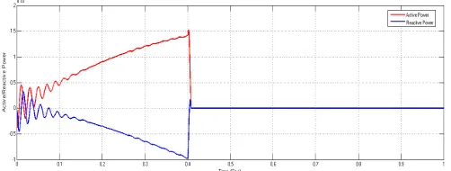
[image:6.612.187.438.501.596.2]Fig. 7 Grid Active power and Reactive Power (Grid Connected mode upto 0.4 sec)
Technology (IJRASET)
Fig. 9 Active power and frequency variation in grid connected mode and under different loading condition
From Fig. 7, it is observed that, the microgrid is connected to the main grid supplying power to the grid during t=0 sec to t=0.4 sec. The Fig. 8, shows the voltage and load current. At t=0.4 sec, the grid is disconnected and the microgrid operates in islanded mode and a load of 25 KW is added, where the frequency is increased to 50.5 Hz with corresponding increase in load current as shown in Figure 4.8.
At t=0.6 sec, a load of 50 KW is added, where the frequency of 50Hz is reached as shown in Fig. 9, with corresponding increase in load current as shown in From the above simulation results, it is observed that during the grid connected mode, the microgrid is supplying power to the grid. Whereas, in islanded mode of operation, the droop control technique is found to be effective in controlling the P and QEfor different load conditions.
C. Parallel Operation of DGs in a Microgrid
The structure of the system is shown in Fig. 10, which includes multiple DGs operating in parallel sharing a common load. The Table-2 shows the system parameters considered to implement the droop control technique in parallel operation of inverters in a microgrid to realize the equal load sharing among the inverters. The microgrid is operated in islanded mode throughout the simulation study.
Inverter
Dc Source L
C
Load
Inverter
Dc Source L
[image:7.612.174.451.405.511.2]C
Fig. 10 Structure of parallel inverters in a microgrid TABLE III
SYSTEM PARAMETERS
Parameters Inverter-1 Inverter-2
Rating of the Inverter 70 KVA 70 KVA
Input DC Voltage Vdc 800V 800V
Filter Inductance 0.6 mH 0.6 mH
Filter Capacitance 1500 µF 1500 µF
KP 10 10
KI 100 100
Load L1 30 KW and 30 KVar
30 KW and 30 KVar 30 KW and 30 KVar Load L2
Technology (IJRASET)
D. Modes of Operation
The operation of the microgrid consists of three modes with R and RL loads, they are:
The designed system is simulated with a load of 30 KW and 30 Kvar from t=0 sec to t= 0.4 sec At t=0.4 sec, a load of 30 KW and 30 Kvar has added (60 KW and 60 Kvar in Total)
At t=0.6 sec a load of 30 KW and 30 Kvar is added (90 KW and 90 Kvar in total) The designed system is simulated with a load of 30 KW from t=0 sec to t= 0.4 sec At t=0.4 sec, a load of 30 KW has added (60 KW in total)
At t=0.6 sec a load of 30 KW is added (90 KW in total)
[image:8.612.132.481.229.449.2]The Fig.11 shows the voltage and load current at different loading conditions. The Fig.12 shows, how the load is shared between the two inverters. In all the three modes of operation the load is equally shared among the inverters (1500 KW, 3000 KW and 4500 KW) with RL load.
Fig. 11 Voltage and Load current
Fig. 12 Test of power sharing effect of the droop control method (With R-Load)
The Fig. 13 shows, the sharing of the load between the two inverters. It is observed that during t=0 to 0.4 sec, the total load of 30KW and 30 Kvar is shared equally among the inverter-1 and inverter-2. Similarly, from, t=0.4 to t=0.6 sec and t=0.6 to 1 sec., the load is increased in steps of 30 KW and 30 Kvar.
[image:8.612.163.457.560.697.2]In all the three modes of operation the load is equally shared among the inverters (1500 KW, 3000 KW, 4500 KW and 1500 KVar, 3000 KVar, 4500 KVar) with RL load. From the results, it is observed that the load sharing is realized accurately among the two inverters in a microgrid using droop control technique.
Technology (IJRASET)
IV.CONCLUSION
This paper presented the operation of a microgrid using droop control strategy. A microgrid is designed to control the voltage and frequency during islanded mode of operation with varying load conditions. Further, this paper also focused on the parallel operation of inverters in a microgrid to realize the equal sharing of the load among the inverters using droop control strategy. To study the effectiveness of the control method, the system is designed and implemented in MATLAB/Simulink environment. The simulation results reveals the fact that the droop control is effective in regulating the voltage and frequency under varying load conditions. Further, the simulation results also reveals that the droop control technique is efficient in sharing the load equally among the parallel inverters.
REFERENCES
[1] M. C. Chandorkar, D. M. Divan and R. Adapa, "Control of parallel connected inverters in standalone AC supply systems," IEEE Transactions on Industry Applications, vol. 29, no. 1, pp. 136-143, Jan/Feb 1993.
[2] Y. A. R. I. Mohamed and A. A. Radwan, "Hierarchical Control System for Robust Microgrid Operation and Seamless Mode Transfer in Active Distribution Systems," IEEE Transactions on Smart Grid, vol. 2, no. 2, pp. 352-362, June 2011.
[3] J. Kim, J. M. Guerrero, P. Rodriguez, R. Teodorescu and K. Nam, "Mode Adaptive Droop Control With Virtual Output Impedances for an Inverter-Based Flexible AC Microgrid," IEEE Transactions on Power Electronics, vol. 26, no. 3, pp. 689-701, March 2011.
[4] D. Shanxu, M. Yu, X. Jian, K. Yong and C. Jian, "Parallel operation control technique of voltage source inverters in UPS," Power Electronics and Drive Systems, 1999. PEDS '99. Proceedings of the IEEE 1999 International Conference on, 1999, pp. 883-887 vol.2.
[5] T. F. Wu, Y. K. Chen and Y. H. Huang, "3C strategy for inverters in parallel operation achieving an equal current distribution," IEEE Transactions on Industrial Electronics, vol. 47, no. 2, pp. 273-281, Apr 2000.
[6] Q. C. Zhong, "Robust Droop Controller for Accurate Proportional Load Sharing Among Inverters Operated in Parallel," IEEE Transactions on Industrial Electronics, vol. 60, no. 4, pp. 1281-1290, April 2013.
[7] M. Guerrero, L. G. de Vicuna, J. Matas, M. Castilla and J. Miret, "A wireless controller to enhance dynamic performance of parallel inverters in distributed generation systems," IEEE Transactions on Power Electronics, vol. 19, no. 5, pp. 1205-1213, Sept. 2004.
[8] M. A. Abusara, J. M. Guerrero and S. M. Sharkh, "Line-Interactive UPS for Microgrids," IEEE Transactions on Industrial Electronics, vol. 61, no. 3, pp. 1292-1300, March 2014.
[9] J. M. Guerrero, L. G. de Vicuna, J. Matas, J. Miret and M. Castilla, "A wireless load sharing controller to improve dynamic performance of parallel-connected UPS inverters," Power Electronics Specialist Conference, 2003. PESC '03. 2003 IEEE 34th Annual, 2003, pp. 1408-1413 vol.3.
[10] W. Yao, M. Chen, M. Gao and Z. Qian, "A wireless load sharing controller to improve the performance of parallel-connected inverters," 2008 Twenty-Third Annual IEEE Applied Power Electronics Conference and Exposition, Austin, TX, 2008, pp. 1628-1631.
[11] E. A. A. Coelho, P. C. Cortizo and P. F. D. Garcia, "Small-signal stability for parallel-connected inverters in stand-alone AC supply systems," in IEEE Transactions on Industry Applications, vol. 38, no. 2, pp. 533-542, Mar/Apr 2002.
[12] J. C. Vasquez, J. M. Guerrero, A. Luna, P. Rodriguez and R. Teodorescu, "Adaptive Droop Control Applied to Voltage-Source Inverters Operating in Grid-Connected and Islanded Modes," in IEEE Transactions on Industrial Electronics, vol. 56, no. 10, pp. 4088-4096, Oct. 2009.
[13] H. J. Avelar, W. A. Parreira, J. B. Vieira, L. C. G. de Freitas and E. A. A. Coelho, "A State Equation Model of a Single-Phase Grid-Connected Inverter Using a Droop Control Scheme With Extra Phase Shift Control Action," in IEEE Transactions on Industrial Electronics, vol. 59, no. 3, pp. 1527-1537, March 2012. [14] R. H. Lasseter and P. Paigi, "Microgrid: a conceptual solution," 2004 IEEE 35th Annual Power Electronics Specialists Conference (IEEE Cat.
No.04CH37551), 2004, pp. 4285-4290 Vol.6.
[15] A. G. Tsikalakis and N. D. Hatziargyriou, "Centralized Control for Optimizing Microgrids Operation," in IEEE Transactions on Energy Conversion, vol. 23, no. 1, pp. 241-248, March 2008.