Technology (IJRASET)
Solar Based Automatic Curtain by Using
Microcontroller
R. Chandana1, R. Gowtham2, V. Hariharan3, M. Kanimozhi4, Dr. L. Jubair Ahmed5 1,2,3,4
Students, 5Assistant Professor
Department of Electronics and Communication Engineering
1,2,3,4,5
Sri Eshwar College of Engineering
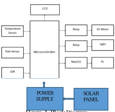
Abstract: Automatic Electronic Curtain Control System is a simple and powerful concept, which uses Relay as a switch to Open and close the Electronic Curtain automatically. By using this system manual works are removed. It automatically Close when the sunlight goes below the visible region of our eyes. It automatically Open under illumination by sunlight. This is done by a sensor called Light Dependent Resistor (LDR) which senses the light actually like our eyes. By using this system energy consumption is also reduced because now-a-days the manually operated Electronic Curtain are not switched off properly even the sunlight comes and also not switched on earlier before sunset. In sunny and rainy days, ON time and OFF time differ significantly which is one of the major disadvantage of using timer circuits or manual operation. This project exploits the working of a transistor in saturation region and cut-off region to switch ON and switch OFF the lights at appropriate time with the help of an electromagnetically operated switch. Electronic Curtain needs no manual operation of Open and Close. The system itself detects whether there is need for open or not. When darkness rises to a certain value then automatically Electronic Curtain close and when there is other source of light, the Electronic Curtain gets Open. The extent of darkness at which the light to be switched on can also be tailored using the relay provided in the circuit. Moreover, the circuit is carefully designed to avoid common problems like overload, relay chattering and inductive kick back in relay.
Keywords-: Curtain, Relay, PIC, LDR, Solar panel, Sensors, Power supply.
I. INTRODUCTION
An embedded system is a computer system designed to perform one or a few dedicated functions, often with real-time computing constraints. It is embedded as part of a complete device often including hardware and mechanical parts. In contrast, a general purpose computer, such as a personal computer, is designed to be flexible and to meet a wide range of an end-user's needs. Embedded systems control many of the common devices in use today. Embedded systems are controlled by a main processing core that is typically either a microcontroller or a digital signal processor (DSP).Since the embedded system is dedicated to specific tasks, design engineers can optimize it, reducing the size and cost of the product, or increasing the reliability and performance. Some embedded systems are mass-produced, benefiting from economies of scale. Physically, embedded systems range from portable devices such as digital watches and MP3 players, to large stationary installations like traffic lights, factory controllers, or the systems controlling nuclear power plants. Complexity varies from low, with a single microcontroller chip, to very high with multiple units, peripherals and networks mounted inside a large chassis or enclosure. In general, "embedded system" is not an exactly defined term, as many systems have some element of programmability. For example, Handheld computers share some elements with embedded systems — such as the operating systems and microprocessors which power them — but are not truly embedded systems, because they allow different applications to be loaded and peripherals to be connected.
II. LITERATURE SURVEY
Technology (IJRASET)
earlier before sunset. The circuit is carefully designed to avoid common problems like overload relay chattering, and inductive kick back in relay.
III. SYSTEM ARCHITECTURE
[image:3.612.212.404.150.337.2]A. System Overview
Figure 1. Block Diagram
B. Introduction of microcontroller
Microcontrollers are destined to play an increasingly important role in revolutionizing various industries and influencing our day to day life more strongly than one can imagine. Since its emergence in the early 1980's the microcontroller has been recognized as a general purpose building block for intelligent digital systems. It is finding using diverse area, starting from simple children's toys to highly complex spacecraft. Because of its versatility and many advantages, the application domain has spread in all conceivable directions, making it ubiquitous. As a consequence, it has generate a great deal of interest and enthusiasm among students, teachers and practicing engineers, creating an acute education need for imparting the knowledge of microcontroller based system design and development. It identifies the vital features responsible for their tremendous impact, the acute educational need created by them and provides a glimpse of the major application area.
C. Circuit diagram
Figure 2.Circuit Diagram
1) Microcontroller: A microcontroller is a complete microprocessor system built on a single IC. Microcontrollers were developed POWER
SUPPLY
[image:3.612.183.398.503.699.2]Technology (IJRASET)
to meet a need for microprocessors to be put into low cost products. Building a complete microprocessor system on a single chip substantially reduces the cost of building simple products, which use the microprocessor's power to implement their function, because the microprocessor is a natural way to implement many products. This means the idea of using a microprocessor for low cost products comes up often. But the typical 8-bit microprocessor based system, such as one using a Z80 and 8085 is expensive. Both 8085 and Z80 system need some additional circuits to make a microprocessor system. Each part carries costs of money. Even though a product design may requires only very simple system, the parts needed to make this system as a low cost product. To solve this problem microprocessor system is implemented with a single chip microcontroller. This could be called microcomputer, as all the major parts are in the IC. Most frequently they are called microcontroller because they are used they are used to perform control functions. The microcontroller contains full implantation standard MICROPROCESSOR, ROM, RAM, I/0, CLOCK, TIMERS, and also SERIAL PORTS. Microcontroller also called "system on a chip" or "single chip microprocessor system" or "computer on a chip". A microcontroller is a Computer-On-A-Chip, or, if you prefer, a single-chip computer. Micro suggests that the device is small, and controller tells you that the device' might be used to control objects, processes, or events. Another term to describe a microcontroller is embedded controller, because the microcontroller and its support circuits are often built into, or embedded in, the devices they control. Today microcontrollers are very commonly used in wide variety of intelligent products. For example most personal computers keyboards and implemented with a microcontroller. It replaces Scanning, Debounce , Matrix Decoding, and Serial transmission circuits. Many low cost products, such as Toys, Electric Drills, Microwave Ovens, VCR and a host of other consumer and industrial products are based on microcontrollers.
2) Evolution of Microcontroller: Markets for microcontrollers can run into millions of units per application. At these volumes of the microcontrollers is a commodity items and must be optimized so that cost is at a minimum. .Semiconductor manufacturers have produced a mind-numbing array of designs that would seem to meet almost any need. Some of the chips listed in this section are no longer regular production, most are current, and a few are best termed as "smoke ware": the dreams of an aggressive marketing department.
3) Application: A microcontroller is a kind of miniature computer that you can find in all kinds of Gizmos. Some examples of common, every-day products that have microcontrollers are built-in. If it has buttons and a digital display, chances are it also has a programmable microcontroller brain .Every-Day the devices used by ourselves that contain Microcontrollers. Try to make a list and counting how many devices and the events with microcontrollers you use in a typical day. Here are some examples: if your clock radio goes off, and you hit the snooze button a few times in the morning, the first thing you do in your day is interact with a microcontroller. Heating up some food in the microwave oven and making a call on a cell phone also involve operating microcontrollers. That's just the beginning. Here are a few more examples: were microcontroller plays a vital role is remote controls. Micro controller is a stand alone unit ,which can perform functions on its own without any requirement for additional hardware like i/o ports and external memory. The heart of the microcontroller is the CPU core. In the past, this has traditionally been based on a 8-bit microprocessor unit. For example Motorola uses a basic 6800 microprocessor core in their 6805/6808 microcontroller devices. In the recent years, microcontrollers have been developed around specifically designed CPU cores, for example the microchip PIC range of microcontrollers.
D. Introduction to PIC
The microcontroller that has been used for this project is from PIC series. PIC microcontroller is the first RISC based microcontroller fabricated in CMOS (complimentary metal oxide semiconductor) that uses separate bus for instruction and data allowing simultaneous access of program and data memory. The main advantage of CMOS and RISC combination is low power consumption resulting in a very small chip size with a small pin count. The main advantage of CMOS is that it has immunity to noise than other fabrication techniques.
1) PIC (16F877): Various microcontrollers offer different kinds of memories. EEPROM, EPROM, FLASH etc. are some of the memories of which FLASH is the most recently developed. Technology that is used in pic16F877 is flash technology, so that data is retained even when the power is switched off. Easy Programming and Erasing are other features of PIC 16F877.
Technology (IJRASET)
programmer gives the product developer ability to program user software in to any of the supported microcontrollers. The PIC start plus software running under MP lab provides for full interactive control over the programmer.
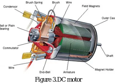
E. DC Motor
[image:5.612.211.399.187.324.2]A DC motor is an AC synchronous electric motor that from a modeling perspective looks very similar to a DC motor. Sometimes the difference is explained as an electronically-controlled commutation system, instead of a mechanical commutation system, although this is misleading, as physically the two motors are completely different. (The rest of this article assumes the reader is familiar with the principles of electrical motors.)
Figure 3.DC motor
Three subtypes exist
The three-phase AC synchronous motor type has three electrical connections The stepper motor type may have more poles on the stator.
The reluctance motor has all its poles on the stator, and a magnetic core on the rotor.
In a conventional (brushed) DC-motor, the brushes make mechanical contact with a set of electrical contacts on the rotor (called the commutator ), forming an electrical circuit between the DC electrical source and the armature coil-windings. As the armature rotates on axis, the stationary brushes come into contact with different sections of the rotating commutator. The commutator and brush-system form a set of electrical switches, each firing in sequence, such that electrical-power always flows through the armature-coil closest to the stationary stator (permanent magnet).
In a BLDC motor, the electromagnets do not move; instead, the permanent magnets rotate and the armature remains static. This gets around the problem of how to transfer current to a moving armature. In order to do this, the brush-system/commutator assembly is replaced by an intelligent electronic controller. The controller performs the same power-distribution found in a brushed DC-motor, but using a solid-state circuit rather than a commutator/brush system.
1) Controller Implementations: Because the controller must direct the rotor rotation, the controller needs some means of determining the rotor's orientation/position (relative to the stator coils.) Some designs use Hall effect sensors or a rotary encoder to directly measure the rotor's position. Others measure the back EMF in the coils to infer the rotor position, eliminating the need for separate Hall effect sensors, and therefore are often called "sensor less" controllers. Like an AC motor, the voltage on the coils is sinusoidal, but over an entire commutation the output appears trapezoidal because of the DC output of the controller. The controller contains 3 bi-directional drivers to drive high-current DC power, which are controlled by a logic circuit. Simple controllers employ comparators to determine when the output phase should be advanced, while more advanced controllers employ a microcontroller to manage acceleration, control speed and fine-tune efficiency. Controllers that sense rotor position based on back-EMF have extra challenges in initiating motion because no back-EMF is produced when the rotor is stationary. This is usually accomplished by beginning rotation from an arbitrary phase, and then skipping to the correct phase if it is found to be wrong. This can cause the motor to run briefly backwards, adding even more complexity to the startup sequence.
Technology (IJRASET)
(This image does not illustrate a BLDC motor's inductive and generator-like properties)
BLDC motors can be constructed in several different physical configurations: In the 'conventional' (also known as 'in runner') configuration, the permanent magnets are mounted on the spinning armature (rotor.) Three stator windings surround the rotor. In the 'out runner' configuration, the radial-relationship between the coils and magnets are reversed; the stator coils form the center (core) of the motor, while the permanent magnets spin on an overhanging rotor which surrounds the core. The flat type, used where there are space or shape limitations, uses stator and rotor plates, mounted face to face. Out runners typically have more poles, set up in triplets to maintain the 3 groups of windings, and have a higher torque at low RPMs. In all BLDC motors, the stator-coils are stationary.
There are also two electrical configurations having to do with how the wires from the windings are connected to each other (not their physical shape or location). The delta winding connects the 3 groups of windings to each other in a triangle-like circuit, and power is applied at each of the connections. This pattern is typical to low-speed, low-torque motors. The wye ("Y"-shaped) winding, sometimes called a star winding, connects all of the windings to a central point and power is applied to the remaining end of each winding.
Although efficiency is greatly affected by the motor's construction, the wye winding is normally more efficient. At any given time, two-thirds of the windings in a delta configuration are running at half the voltage of the other, which is an impact on efficiency. The wye winding always powers only two windings in series, so higher voltages (or lower-resistance windings) can be used.
From a controller standpoint, the two styles of windings are treated exactly the same, although some less expensive controllers need to read voltage from the common center of the wyes winding.
3) Applications: BLDC motors can potentially be deployed in any field-application currently fulfilled by brushed DC motors. Cost and control complexity prevents BLDC motors from replacing brushed motors in most common areas of use. Nevertheless, BLDC motors have come to dominate many applications: Consumer devices such as computer hard drives, CD/DVD players, and PC cooling fans use BLDC motors almost exclusively. Low speed, low power brushless DC motors are used in direct-drive turntables. High power BLDC motors are found in electric vehicles and some industrial machinery. These motors are essentially AC synchronous motors with permanent magnet rotors.
F. Power Supply
The ac voltage, typically 220V rms, is connected to a transformer, which steps that ac voltage down to the level of the desired dc output. A diode rectifier then provides a full-wave rectified voltage that is initially filtered by a simple capacitor filter to produce a dc voltage. This resulting dc voltage usually has some ripple or ac voltage variation.
[image:6.612.230.506.608.681.2]A regulator circuit removes the ripples and also remains the same dc value even if the input dc voltage varies, or the load connected to the output dc voltage changes. This voltage regulation is usually obtained using one of the popular voltage regulator IC units.
Figure. 4. Block diagram of Power Supply TRANSF
ORMER
RECTI
FIER FILTER
IC REGULATOR
Technology (IJRASET)
1) Working principle
a) Transformer: The transformer will step down the power supply voltage (0-230V) to (0-6V) level. Then the secondary of the potential transformer will be connected to the precision rectifier, which is constructed with the help of op–amp. The advantages of using precision rectifier are it will give peak voltage output as DC; rest of the circuits will give only RMS output.
b) Rectifier: The rectifier is device which converts Alternating current into some DC form. The output of the rectifier is in pulsated DC form. There is some semiconductor devices used to convert AC to pulsated DC named diodes. Normally we are using PN junction diodes in rectifiers. These diodes allow the current flow to it when the incoming voltage is higher than or equal to 0.7 V. otherwise it will act as an open circuit.
c) Filter: The next section of the power supply is filter section. That is nothing but capacitor. The capacitor is used as a filter to convert Pulsated DC to pure DC. We can utilize the capacitor’s charging discharging characteristics and convert the pulsated DC to pure DC.
d) Voltage Regulator: Voltage regulators comprise a class of widely used ICs. Regulator IC units contain the circuitry for reference source, comparator amplifier, control device, and overload protection all in a single IC. IC units provide regulation of either a fixed positive voltage, a fixed negative voltage, or an adjustably set voltage. The regulators can be selected for operation with load currents from hundreds of milli amperes to tens of amperes, corresponding to power ratings from milli watts to tens of watts.
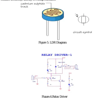
G. LDR [Light -Dependant-Resistor]
Photoresistor or LDR is an electronic component whose resistance decreases with increasing incident light intensity. It can also be referred to as a light-dependent resistor (LDR), photoconductor, or photocell.
[image:7.612.125.512.374.712.2]A photoresistor is made of a high-resistance semiconductor. If light falling on the device is of high enough frequency, photons absorbed by the semiconductor give bound electrons enough energy to jump into the conduction band. The resulting free electron (and its hole partner) conduct electricity, thereby lowering resistance.
Figure 5. LDR Diagram
H. Relay Driver
Figure.6.Relay Driver
Technology (IJRASET)
containing a device such as a lamp or electric motor which requires a large current, or if we wish several different switch contacts to be operated simultaneously.
When the controlling current flows through the coil, the soft iron core is magnetized and attracts the L-shaped soft iron armature. This rocks on its pivot and opens, closes or changes over, the electrical contacts in the circuit being controlled it closes the contacts. The current needed to operate a relay is called the pull-in current and the dropout current in the coil when the relay just stops working. If the coil resistance R of a relay is 185 and its operating voltage V is 12V, the pull-in current I is given by:
I = V = 12 = 0.065A = 65mA
R 185
Relay driver circuit is used for on / off control of relay, it acts as a switch, normally open relay is used. Relay function is derived by controller unit. Relay working current is 40 ma.
When the controller unit output is low relay should be in off condition. When the controller unit output is high, relay should be ready for doing specified function.
I. LCD (Liquid Crystal Display)
1) Introduction: The most commonly used Character based LCDs are based on Hitachi's HD44780 controller or other which are compatible with HD44580. In this tutorial, we will discuss about character based LCDs, their interfacing with various microcontrollers, various interfaces (8-bit/4-bit), programming, special stuff and tricks you can do with these simple looking LCDs which can give a new look to your application.
Figure.7.LCD Display Pin Configuration
J. Temperature Sensor
LM35 is a precision IC temperature sensor with its output proportional to the temperature (in oC). The sensor circuitry is sealed and therefore it is not subjected to oxidation and other processes. With LM35, temperature can be measured more accurately than with a thermistor. It also possess low self-heating and does not cause more than 0.1 oC temperature rise in still air.
The operating temperature range is from -55°C to 150°C. The output voltage varies by 10mV in response to every oC rise/fall in ambient temperature, i.e., its scale factor is 0.01V/ oC.
Figure.8.PIN Diagram Of LM35
K. Rain Sensor
Technology (IJRASET)
the surface, however; some evaporates while falling through dry air. When none of it reaches the ground, it is called virga, a phenomenon often seen in hot, dry desert regions. The scientific explanation of how rain forms and falls is called the Bergeron process.
Rain plays a role in the hydrologic cycle in which moisture from the oceans evaporates, condenses into clouds, precipitates back to earth, and eventually returns to the ocean via streams and rivers to repeat the cycle again. There is also a small amount of water vapor that respires from plants and evaporates to join other water molecules in condensing into clouds.
The amount of rainfall is measured using a rain gauge. It is expressed as the depth of water that collects on a flat surface, and is routinely measured with an accuracy up to 0.1 mm or 0.01 in. It is sometimes expressed in liters per square meter (1 liter/m² = 1 mm).
[image:9.612.192.409.330.522.2]This circuit is designed with two lines are tracked with very short distance. When rain drops falls on this circuit, the track may become short circuit. It gives the corresponding signal to related circuit in order to find the rain fall
Figure 9.Rain Sensor
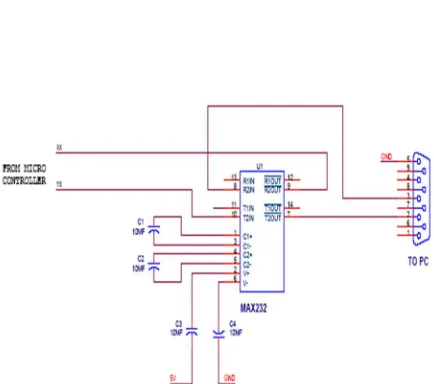
L. RS232 Communication
Figure.10.RS232 Communication
1) RS232: In telecommunications, RS-232 is a standard for serial binary data interconnection between a DTE (Data terminal equipment) and a DCE (Data Circuit-terminating Equipment). It is commonly used in computer serial ports.
2) Scope of Standards: The standard does not define such elements as character encoding (for example, ASCII, Baud or EBCDIC), or the framing of characters in the data stream (bits per character, start/stop bits, parity). The standard does not define protocols for error detection or algorithms for data compression. The standard does not define bit rates for transmission, although the standard says it is intended for bit rates lower than 20,000 bits per second. Many modern devices can exceed this speed (38,400 and 57,600 bit/s being common, and 115,200 and 230,400 bit/s making occasional appearances) while still using RS-232 compatible signal levels.Details of character format and transmission bit rate are controlled by the serial port hardware, often a single integrated circuit called a UART that converts data from parallel to serial form. A typical serial port includes specialized driver and receiver integrated circuits to convert between internal logic levels and RS-232 compatible signal levels.
Technology (IJRASET)
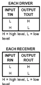
[image:10.612.149.553.56.548.2]receiver converts EIA-232 to 5v TTL/CMOS levels. Each driver converts TLL/CMOS input levels into EIA-232 levels.
Table. 1. RS232 Communication
Figure.11.RS232.Logic Diagram
In this circuit the microcontroller transmitter pin is connected in the MAX232 T2IN pin which converts input 5v TTL/CMOS level to RS232 level. Then T2OUT pin is connected to reviver pin of 9 pin D type serial connector which is directly connected to PC. In PC the transmitting data is given to R2IN of MAX232 through transmitting pin of 9 pin D type connector which converts the RS232 level to 5v TTL/CMOS level. The R2OUT pin is connected to receiver pin of the microcontroller. Likewise the data is transmitted and received between the microcontroller and PC or other device vice versa.
M. Solar Panel
The sun is responsible for all of the earth energy. Plants use the sun's light to make food. Decaying plants hundreds of millions of years ago produced the coal, oil and natural gas that we use today.
Solar energy is created by light and heat which is emitted by the sun, in the form of electromagnetic radiation. Solar energy is most commonly collected by using solar cells. A solar panel is a device that collects and converts solar energy into electricity or
[image:10.612.278.362.112.283.2]Technology (IJRASET)
Figure.12.Solar Panel
Figure.13.Graph for solar panel output
IV. CODING DESIGN
#include<pic.h> #include<New-lcd.h> __CONFIG(0x1F31);
static bit rain @((unsigned) &PORTD*8+0); //motor on static bit in_ldr @((unsigned) &PORTC*8+2);
Technology (IJRASET)
static bit re_rly @((unsigned) &PORTD*8+3);static bit lig_rly @((unsigned) &PORTD*8+2);
void mcu_init(); void adc0(); void msg_tx(); void ser_init();
void ser_out(unsigned char ss);
void ser_dis(const unsigned char*da,unsigned char no); void close();
void open();
unsigned int tmp,temp,x; unsigned char i,st; void main() {
//SOLAR BASED AUTOMATIC ELECTRONIC CURTAIN mcu_init();re_rly=fw_rly=lig_rly=0;
lcd_init(); ser_init(); read(0x01); read(0x80);
lcd_dis(" SOLAR BASED ",16); read(0xc0);
lcd_dis(" AUTOMATIC ",16); del();del();
read(0x80);
lcd_dis(" ELECTRONIC ",16); read(0xc0);
lcd_dis(" CURTAIN ",16); del();del();
read(0x80);
lcd_dis("TEMP: RAIN:NO ",16); read(0xc0);
lcd_dis("IN:NO OUT:NO ",16); while(1) { x++; adc0(); if(rain==0){read(0x8D);lcd_dis("YES",3);} else { read(0x8D);lcd_dis("NO ",3);
if(out_ldr==1 && st==0){st=1;open();} else if(out_ldr==0 && st==1){st=0;close();} }
if(in_ldr==1){lig_rly=0;read(0xC4);lcd_dis("YE S",3);} else {lig_rly=1;read(0xC4);lcd_dis("NO ",3);}
Technology (IJRASET)
}void adc0() {
tmp=0;
for(i=0;i<10;i++) {
ADCON0=0x00; // Channel select
ADON=1; delay(255);
ADCON0=0x05; // selecting a particular channel and making the go/done bit high while(ADCON0!=0x01); // cheking whether the go/done bit is cleared
temp=ADRESH; tmp=tmp+temp; }
temp=(tmp/10)-220; read(0x85);
write((temp/10)+0x30); write(temp%10+0x30); delay(200);
}
void ser_init() {
SPBRG= 25; // for 9600 baud rate 4MHz crystal BRGH = 1; // baud rate high SYNC = 0; // asynchronous mode
SPEN = 1; // serial port enable RCIE = 1; // interrupt set CREN = 1; // Rx enable
TXEN = 1; // Tx enable
GIE=1;PEIE=1; }
void ser_out(unsigned char ss) {
TXREG = ss; while(!TXIF); TXIF = 0; delay(8000); }
void ser_dis(const unsigned char*da,unsigned char no) {
unsigned char ss;
Technology (IJRASET)
V. SCREENSHOTS
VI. CONCLUSION
This project profile envisages the production of Automatic Curtain Opener by setting up of a unit in a small scale sector. The Automatic Curtain opener are used for opening and closing of the stage of any good theatre, auditorium conference hall etc. The mechanism should automatically open and close the curtain depending on the situation of the function being performed on the stage. The motor once started will run for the duration required to open/close the curtain fully then stop. And we have advantage in this project that is human intervention is not needed. And the market potential is enormous. With rapid industrialization in urban and semi urban, with more entertainment centres coming up, with more conference/seminar halls coming up in the Government, private sectors the demand of Automatic Curtain Opener is enormous
VII. ACKNOWLEDGEMENT
The Authors acknowledge the contribution of the students, faculty of Sri Eshwar College Of Engineering ,Kinathukadavu for helping in the design and for tool support. The Authors also thank the anonymous reviewers for their thoughtful comments that helped to improve this paper.
REFERENCES
[1] Alkar,A.Z.,&Buhur,U.(2005),An Internet Based Wireless Home Automation System For Multifunctional Devices, IEEE Consumer electronics ,51(4),pp.1169-1174.
[2] P.Atten, H.L.Pang,and J.L.Reboud,”Study of dust removeable by standing wave electric curtain for application for solar cells on mass.”IEEE Transactions on industry application ,vol.45,pp.75 -86(2009).
[3] Jianjun Lv,Zhishu Li,Mingyi Mao.”Anew USB home appliances based on PC and infrared remote control protocol”.2010 International Conference on Computer and Communication Technologies in Agriculture Engineering .2010,pp.572-575.
[4] Conte, G., & Scaradozzi, D. (2003), Viewing home automation systems as multiple agents systems, RoboCUP2003,Padova, Italy. [5] David Bodanis (2005). Electric Universe, Crown Publishers, New York. ISBN 0-7394-5670-9.
[6] Dorf, R. (1997), Electrical Engineering Handbook, 2nd edition, Boca Raton, Fla.: CRC. [7] Gibilisco, S. (1999), Electronics Portable Handbook, New York: McGraw-Hill. [8] Gibilisco, S. (1999), Electronics Formulas Pocket Reference, New York: McGraw-Hill.
[9] Grant McFarland, Microprocessor design: a practical guide from design planning to manufacturing p.10, McGraw- Hill Professional, 2006 ISBN 0-07-145951-0.
[10] Horowitz, Paul; Winfield Hill (1989). The Art of Electronics, 2nd edition, Cambridge University Press.
[11] Potamitis, I., Georgila, K., Fakotakis, N., & Kokkinakis, G. (2003), “An integrated system for smart-home control of appliances based on remote speech interaction”, EUROSPEECH 2003,
[12] 8th European Conference on Speech Communication and Technology, Geneva, Switzerland, Sept. 1-4, 2003, pp. 2197-2200. [13] Smith, R. J. (1980), Electronics: Circuits and Devices, 2nd edition. New York: John Wiley & Sons, Inc.
[14] Webster, J. G., Wile (1999) Encyclopedia of Electrical and Electronics Engineering, vol4. New York: John Wiley Sons, Inc.
[15] Zungeru, A.M. et al., (2012). Design and Implementation of a Low Cost Digital Bus Passenger Counter. InnovativeSystems Design and Engineering, pg. 29– 41.
[16] Zungeru, A.M., Edu, U., & Garba, A. (2012). Design and Implementation of a Short Message Service, Based RemoteController, Computer Engineering and Intelligent systems, pg.106–118.