Technology (IJRASET)
Implementation of Active Relay Node for Efficient
Path Planning In Intelligent VANET
Communication System
P.Kalaiselvi1, C.Aswin2 ,M.Manoj Kumar3,M.Preetha4
1
Assistant Professor, 2,3,4UG Scholar, ECE Department N.S.N College of Engineering and Technology, Karur, India
Abstract— Vehicular Ad hoc Networks (VANET) consists of radio-equipped vehicles and roadside units (RSU) and support many safety and commercial applications. Multi-hop forwarding can extend the communication range of both RSUs and vehicular broadcasts. Recently, the use of relay node selection as transmission patterns of repetition-based broadcast medium access control (MAC) for safety messages has been proposed. This thesis proposes a cooperative forwarding protocol in which multiple relays at each forwarding hop form a virtual relay and coordinate their transmission times to correspond to a relay node selection. The protocol thereby exploits spatial diversity while conforming to the relay node selection -based MAC, resulting in fewer collisions and mitigating the effect of hidden terminals. The design is validated through NS2 simulations, which show comparable performance with other forwarding schemes while producing significantly less performance degradation for safety message broadcasts on the same channel.
Keywords—RSU,relay node selection,medium access protocol,multi hop forwarding.
I. INTRODUCTION
VANETs support a wide range of applications - from simple one hop information dissemination of, e.g., cooperative awareness messages (CAMs) to multi-hop dissemination of messages over vast distances. Most of the concerns of interest to mobile ad hoc networks (MANETs) are of interest in VANETs, but the details differ. Rather than moving at random, vehicles tend to move in an organized fashion. The interactions with roadside equipment can likewise be characterized fairly accurately. And finally, most vehicles are restricted in their range of motion, for example by being constrained to follow a paved highway.
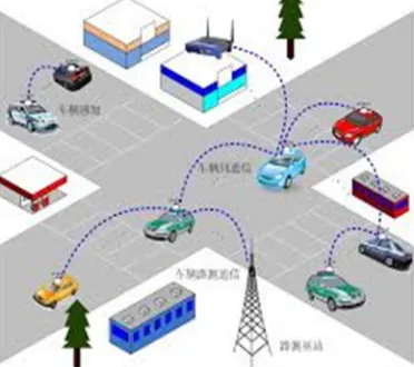
[image:2.612.212.398.541.706.2]Intelligent vehicular ad hoc networks (in VANETs) use WIFI IEEE 802.11p (wave standard) and wimax IEEE 802.16 for easy and effective communication between vehicles with dynamic mobility. Effective measures such as media communication between vehicles can be enabled as well methods to track automotive vehicles. Automotive vehicular information can be viewed on electronic maps using the internet or specialized software. The advantage of WIFI based navigation system function is that it can effectively locate a vehicle which is inside big campuses like universities, airports, and tunnels. In VANET can be used as part of automotive electronics, which has to identify an optimally minimal path for navigation with minimal traffic intensity. The system can also be used as a city guide to locate and identify landmarks in a new city.
Technology (IJRASET)
Fig 2: VANET with RSU’s
Vehicular ad hoc network (VANET) is an emerging new technology integrating ad hoc network, wireless LAN (WLAN) and cellular technology to achieve intelligent inter-vehicle communications and improve road traffic safety and efficiency. VANETs are distinguished from other kinds of ad hoc networks by their hybrid network architectures, node movement characteristics, and new application scenarios. Therefore, VANETs pose many unique networking research challenges, and the design of an efficient routing protocol for VANETs is very crucial.
II. INTELLIGENTTRANSPORTATIONSYSTEM
Motivation and Purpose Vehicular accidents have claimed the lives of more Canadians over the past 50 years than the two world wars combined; each day eight Canadians on average die in vehicular collisions. On a global scale, the social and economic impact of road accidents is staggering. The World Health Organization (WHO) and the World Bank estimate their direct economic cost at US$ 518 billion. In terms of global burdens of disease and injury, traffic accidents are projected to become the third highest contributor of disability adjusted life years (DALY) by 2020.
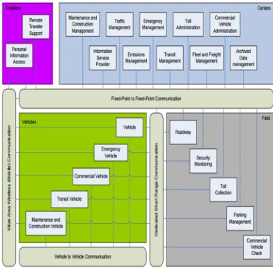
A roadmap for the next generation of vehicle safety-enhancing technology is defined under the banner of Intelligent Transportation Systems (ITS), which aim to improve road travel by preventing accidents, managing traffic volume, and streamlining toll collection, etc. A key component of the ITS framework is a vehicular communication network that provides low-latency and highly-reliable communication amongst vehicles and between vehicles and the roadside infrastructure. The ITS architecture as defined by the U.S. Department of Transportation is illustrated in Fig 1. It is evident that the many envisioned applications and services depend on the viability of the underlying communication platform. Therefore, ITS and safety-enhancing applications in particular have motivated the field of vehicular ad hoc networks (VANET) as a key enabling technology.
Technology (IJRASET)
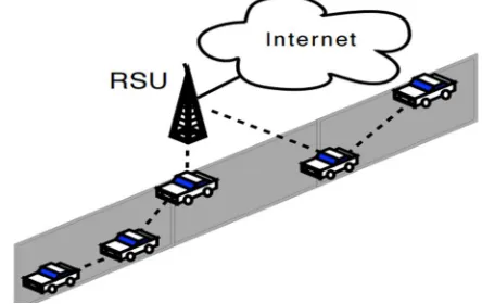
[image:4.612.192.414.175.315.2]Reference categorizes ITS applications under each of these two types of communication. While V2V applications are mostly safety-related, V2I applications include both safety applications and commercial applications such as electronic toll collection and in-vehicle advertising. These V2I applications require a wireless connection between vehicles and stationary Road Side Units (RSU) deployed along the length of the road. A significant obstacle to the deployment of ITS systems on today’s highways is the deployment and maintenance cost of the number of RSUs required to provide coverage over the length of the road. If the effective coverage range of an individual RSU could be extended through multi-hop V2V relaying as illustrated in Fig. 3, then the number of RSUs needed to cover a given stretch of highway could be reduced.
Fig 4: Use of multi-hop to extend the coverage of an RSU. A. Intelligent Transport Technologies
Intelligent transport systems vary in technologies applied, from basic management systems such as car navigation; traffic signal control systems; container management systems; variable message signs; Additionally, predictive techniques are being developed to allow advanced modelling and comparison with historical baseline data. Some of these technologies are described in the following sections.
B. Wireless Communications
Various forms of wireless communications technologies have been proposed for intelligent transportation systems. Radio modem communication on UHF and VHF frequencies are widely used for short and long range communication within ITS. Short-range communications of 350 m can be accomplished using IEEE 802.11 protocols, specifically WAVE or the Dedicated Short Range Communications standard being promoted by the Intelligent Transportation Society of America and the United States Department of Transportation. Theoretically, the range of these protocols can be extended using Mobile ad hoc networks or Mesh networking. C. Sensing Technologies
Technological advances in telecommunications and information technology, coupled with ultramodern/state-of-the-art microchip, RFID (Radio Frequency Identification), and inexpensive intelligent beacon sensing technologies, have enhanced the technical capabilities that will facilitate motorist safety benefits for intelligent transportation systems globally. Sensing systems for ITS are vehicle- and infrastructure-based networked systems, i.e., Intelligent vehicle technologies. Infrastructure sensors are indestructible (such as in-road reflectors) devices that are installed or embedded in the road or surrounding the road (e.g., on buildings, posts, and signs), as required, and may be manually disseminated during preventive road construction maintenance or by sensor injection machinery for rapid deployment.
D. Inductive Loop Detection
Inductive loops can be placed in a roadbed to detect vehicles as they pass through the loop's magnetic field. The simplest detectors simply count the number of vehicles during a unit of time (typically 60 seconds in the United States) that pass over the loop, while more sophisticated sensors estimate the speed, length, and class of vehicles and the distance between them. Loops can be placed in a single lane or across multiple lanes, and they work with very slow or stopped vehicles as well as vehicles moving at high-speed. E. Video Vehicle Detection
Technology (IJRASET)
the road surface or roadbed, this type of system is known as a "non-intrusive" method of traffic detection. Video from cameras is fed into processors that analyse the changing characteristics of the video image as vehicles pass.Some systems provide additional outputs including gap, headway, stopped-vehicle detection, and wrong-way vehicle alarms.
F. Bluetooth Detection
Bluetooth is an accurate and inexpensive way to measure travel time and make origin and destination analysis. Bluetooth is a wireless standard used to communicate between electrondresses from Bluetooth devices in passing vehicles. If these sensors are interconnected they are able to calculate travel time and provide data for origin and destination matrices.
G. Audio Detection
It is also possible to measure traffic density on a road using the Audio signal that consists of the cumulative sound from tire noise, engine noise, engine-idling noise, honks and air turbulence noise. A roadside-installed microphone picks up the audio that comprises the various vehicle noise and Audio signal processing techniques can be used to estimate the traffic state. The accuracy of such a system compares well with the other methods described above.
III. MOTIONPLANNING
Motion planning (also known as the navigation problem or the piano mover's problem) is a term used in robotics for the process of breaking down a desired movement task into discrete motions that satisfy movement constraints and possibly optimize some aspect of the movement.
A. Concepts
A basic motion planning problem is to produce a continuous motion that connects a start configuration S and a goal configuration G, while avoiding collision with known obstacles. The robot and obstacle geometry is described in a 2D or 3D workspace, while the motion is represented as a path in (possibly higher-dimensional) configuration space.
B. Configuration Space
A configuration describes the pose of the robot, and the configuration space C is the set of all possible configurations. For example: If the robot is a single point (zero-sized) translating in a 2-dimensional plane (the workspace), C is a plane, and a configuration can be represented using two parameters (x, y).
If the robot is a 2D shape that can translate and rotate, the workspace is still 2-dimensional.
If the robot is a solid 3D shape that can translate and rotate, the workspace is 3-dimensional.
If the robot is a fixed-base manipulator with N revolute joints (and no closed-loops), C is N-dimensional. C. Free Space
The set of configurations that avoids collision with obstacles is called the free space Cfree. The complement of Cfree in C is called the
obstacle or forbidden region.Often, it is prohibitively difficult to explicitly compute the shape of Cfree. However, testing whether a
given configuration is in Cfree is efficient. First, forward kinematics determine the position of the robot's geometry, and collision
detection tests if the robot's geometry collides with the environment's geometry. D.Completeness And Performance
A motion planner is said to be complete if the planner in finite time either produces a solution or correctly reports that there is none. Most complete algorithms are geometry-based. The performance of a complete planner is assessed by its computational complexity. Probabilistic completeness is the property that as more “work” is performed, the probability that the planner fails to find a path, if one exists, asymptotically approaches zero. Several sample-based methods are probabilistically complete. The performance of a probabilistically complete planner is measured by the rate of convergence.
Technology (IJRASET)
IV. HYBRIDCOMMUNICATION
The Vehicular Ad-hoc Network (VANET), a variant of the Mobile Ad-hoc Network (MANET), is a continuously self configuring, infrastructure less network. The Mobile nodes in VANET are vehicle equipped with On-Board Units (OBU), which are wireless communication devices, OBUs used to enable vehicles in VANET to exchange traffic messages with nearby mobile nodes. Communications in VANETs can be divided into two types’ vehicle-to-vehicle communication (V2V) and vehicle-to-infrastructure communication (V2I). Both type of communication are controlled by a short range wireless communication protocol, called the Dedicated Short Range Communication (DSRC) protocol and each vehicles communicate with nearby vehicles and Road Side Units (RSUs) located at roadside can communicate with the traffic control center through the Internet.
A. Relay Node Selection-Based Cooperative Forwarding
This paper presented repetition-based MAC protocols for vehicular broadcast and in particular the RELAY NODE SELECTION-based scheme proposed. However, repetitions within a time frame cannot account for the effects of slow-fading channels and nodes suffering from shadowing effects from obstacles. One well-known method of dealing with these problems is by exploiting spatial diversity and the broadcast nature of wireless transmissions, that is, the independent channel conditions of antennas located at different points in space.
B. A Simple Multi-Relay Forwarding Scheme
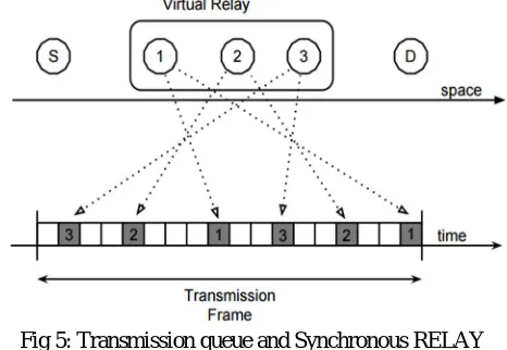
[image:6.612.190.423.373.534.2]To motivate many of the features of the proposed scheme described later in this chapter, let us first consider a naive design of a multi-relay multi-hop forwarding scheme. In designing the routing layer separately from the MAC layer, a naive approach would be to implement a position-based routing scheme such as GPSR or CBF on top of the RELAY NODE SELECTION based MAC. For example, by taking CBF’s approach to opportunistic forwarding, we arrive at a multi-relay forwarding scheme in which a packet’s optimal forwarder is found through contention among the successful receivers of the transmission of the previous hop.
Fig 5: Transmission queue and Synchronous RELAY NODE SELECTION-MAC for w = 3 and
L = 10.
Each relay will then place its ID and position information in the packet header, update the packet’s hop count, and add w copies of the received packet to its FIFO transmission queue.
C. The Proposed Cooperative Forwarding Protocol
While other multi-relay forwarding schemes exist in literature, the main novel ideas of the scheme proposed in the remainder of this chapter are a) to temporarily assign additional transmission opportunities to the transmission frame of relay nodes; and b) to coordinate the relaying nodes’ transmission times in a structured way, specifically, according to a RELAY NODE SELECTION codeword.
D. Virtual Relays
Technology (IJRASET)
Fig 6: Round-robin time slot assignment for a 3-node virtual relay
In Fig 6, Round-robin time slot assignment for a 3-node virtual relay where w = 6 a virtual relay would appear to the other nodes in the network as if instead an extra “real” relay using the same RELAY NODE SELECTION codeword were added to the network. Finally, the code allocation mechanism for virtual relays will be described in detail.
E. Allocation Scheme for Relay Node Selection-MAC
A distributed code assignment scheme was proposed and will be summarized briefly. The RELAY NODE SELECTION codebook is divided into a set of “permanent codeword’s” and a smaller set of “temporary or tentative codeword’s” used strictly for network association. Express the degree of spatial reuse of this scheme by the maximum code density λC, which is the maximum number of
code words per unit length of the road. Given that there are N code words in the codebook, the code density is λC = N 4R. F. Modified Location-Based Code Allocation Scheme
Let us consider a vehicular network in a chain topology on a one-dimensional stretch of highway. Begin by dividing the RELAY NODE SELECTION codebook C into three equal subsets which we denote by Ca, Cb, and Cc. The highway is then divided into equal segments or zones of length R, and each zone is associated with one of the three codeword subsets of RELAY NODE SELECTION.
V. SIMULATIONRESULT
In our proposed method “The Vehicular Ad-hoc Network (VANET), a variant of the Mobile Ad-hoc Network (MANET), is a continuously self configuring, infrastructure less network. The Mobile nodes in VANET are vehicle equipped with On-Board Units (OBU), which are wireless communication devices, OBUs used to enable vehicles in VANET to exchange traffic messages with nearby mobile nodes. Communications in VANETs can be divided into two types’ vehicle-to-vehicle communication (V2V) and vehicle-to-infrastructure communication (V2I). Both type of communication are controlled by a short range wireless communication protocol, called the Dedicated Short Range Communication (DSRC) protocol and each vehicles communicate with nearby vehicles and Road Side Units (RSUs) located at roadside can communicate with the traffic control center through the Internet”.
[image:7.612.205.412.525.711.2]Technology (IJRASET)
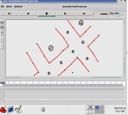
[image:8.612.218.430.182.496.2]In above figure the multi hop network which has more nodes to placed in a particular location and that are redy to communicate with each other.The reliable RELAY NODE SELECTION-MAC protocol for multi-hop communication. The proposed scheme is cooperative in the sense that forwarding is performed by multiple cooperating relays, thereby exploiting spatial diversity in both the sending and receiving nodes at each hop.
Fig 8 explains about if the accident occur in a particular area that will considered as an emergency node and there is a V2V and V2I communication between the neighborhood nodes .In this scheme, those w transmission opportunities are the only times a node may ever send any packets. A node that has generated a new packet to send records the ID and position of the destination in the packet header, along with its own ID as the source and a sequence number.
Fig 8: RSU’S are identified
Fig 9: Nodes are ready to communicate with other
The fig 9 shows the RSU is placed in a particular location for a coverage area. For that we are here using two RSU in road side areas. The nearby node in a particular coverage area that passes the information to RSU. A node that successfully receives a packet will first search the list for its packet ID. If not found, the packet’s ID is added to the list. Next, the receiving node will determine its candidacy for becoming a relay using the position information of the destination and the previous hop sender located in the packet header and its own GPS location. The data broadcasting is done to all the nodes through RSU .In RSU all the vehicle’s ID are stored.
[image:8.612.209.406.602.712.2]Technology (IJRASET)
[image:9.612.189.403.116.272.2]The fig 10 represents the RSU give a request to another node which is in the another coverage area and it treats that node as a active relay node. Each relay will then place its ID and position information in the packet header, update the packet’s hop count, and add w copies of the received packet to its FIFO transmission queue.
Fig 11: Selection of RSU in a coverage area
[image:9.612.200.411.327.480.2]The Fig 11 shows the RSU in a particular coverage area selected for communication among near by nodes and the network connected for communication in a particular coverage area. Also assume that the network has a table of N nodes and each node creates a packet at each time slot with probability Pa.
Fig 12: Data is broadcasted to RSU
[image:9.612.210.405.548.699.2]Fig 12 represents the different node acts as a active relay node to pass the information to neighborhood nodes by using VANET communication system .If we allow each node to transmit not only with its own RELAY NODE SELECTION pattern, but also in designated time slots for forwarding multi-hop traffic which have been assigned to it by the previous hop, each node will be able to transmit with a rate that is greater than that of its RELAY NODE SELECTION (w L).
Technology (IJRASET)
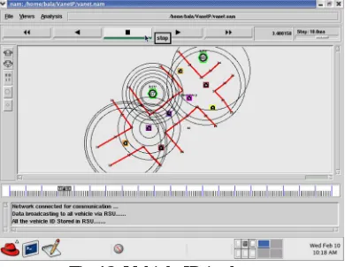
[image:10.612.202.413.133.274.2]Figure 8.7 represents the network is connected for the communication .The data broadcasting is done to all the nodes through RSU .In RSU all the vehicle’s ID are stored. Since transmission opportunities are thus allocated per data flow, nodes located at network bottlenecks will automatically obtain more access opportunities to the broadcast channel. Such an approach should be better suited for V2I communications and is the one taken by the proposed forwarding scheme.
Fig 14: RSU gets connected with the nodes
[image:10.612.209.402.359.517.2]Fig 14 represents the network is connected for the communication .The data broadcasting is done to all the nodes through RSU .In RSU all the vehicle’s ID are stored. While other multi-relay forwarding schemes exist in literature, the main novel ideas of the scheme proposed in the remainder of this chapter are a) to temporarily assign additional transmission opportunities to the transmission frame of relay nodes; and b) to coordinate the relaying nodes’ transmission times in a structured way, specifically, according to a RELAY NODE SELECTION codeword.
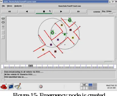
[image:10.612.210.407.577.712.2]Figure 15: Emergency node is created
Fig 15 represents the data broadcasting is done to all vehicle via RSU. Then RSU will identify the fake id and it will reject the fake nodes. The latter feature allows a multi-relay multi-hop forwarding scheme to be integrated with the RELAY NODE SELECTION-based MAC, thereby benefiting from that scheme’s robustness to changes in network topology and the effect of hidden terminals.
Technology (IJRASET)
In Fig 16 represents the emergency vehicle communicate towards target. The nodes changes the mobility apart from accident path. And finally the traffic condition in that area cleared by the implementation of active relay node using intelligent VANET communication system.
VI. CONCLUSION
Thus the process is securing the communication process. Then ide64ntify the original user and control the traffic signals. The function of batch verification of multiple messages is included in the proposed ID-based CPPA scheme. The security analysis shows that the proposed scheme can overcome the weaknesses of previously proposed schemes and satisfy the security requirements of ID-based CPPA schemes for VANETs. Our performance analysis results show that the proposed scheme incurs lower computation cost and communication cost because no bilinear pairings are used in our proposed ID-based CPPA scheme.
REFERENCES
[1] TTI, Texas Transportation Institute: urban mobility information, 2007 Annual Urban Mobility Report.
[2] M. Papageorgiou, C. Diakaki, V. Dinopoulou, A. Kotsialos, and Y. Wang, “Review of road traffic control strategies,” Proc. The IEEE, vol. 91, no. 12, pp. 2043-2067, 2003.
[3] T. Hunter, R. Herring, P. Abbeel, and A. Bayen, “Path and travel time inference from GPS probe vehicle data,” Proc. Neural Information Processing Systems Foundation, Vancouver, Canada, Dec. 2009.
[4] H. Hartenstein and K. Laberteaux, VANET: vehicular applications and inter-networking technologies, John Wiley and Sons Publishers, 2010.
[5] R. Lu, X. Lin, and X. Shen, “SPRING: A social-based privacy- preserving packet forwarding protocol for vehicular delay tolerant networks,” Proc. IEEE INFOCOM, San Diego, USA, Mar. 2010.
[6] M. Wang, H. Liang, R. Zhang, R. Deng, X. Shen, “Mobility-aware coordinated charging for electric vehicles in VANET-enhanced smart grid,” IEEE Journal Selected Areas of Communications, to appear.
[7] A. Skabardonis and N. Geroliminis, “Real-time monitoring and con- trol on signalized arterials,” IEEE Journal of Intelligent Transporta- tion Systems: Technology, Planning, and Operations, vol. 12, no. 2, pp. 64-74, 2008.
[8] I. Leontiadis, G. Marfia, D. Mack, G. Pau, C. Mascolo, and M. Gerla, “On the effectiveness of an opportunistic traffic management system for vehicular networks,” IEEE Trans. on Intelligent Transportation Systems, vol. 12, no. 4, pp. 1537-1548, 2011.