Design of an Optimal Tip Speed Ratio Control
MPPT Algorithm for Standalone WECS
Balasundar.C1, S.Sudharshanan2, R.Elakkiyavendan3
1,2, 3
Department of Electrical and Electronics Engineering, Anna University, Regional Centre Coimbatore
Abstract: This paper presents a design of an optimal tip speed ratio (OTSR) control maximum power point tracking (MPPT) algorithm for standalone wind energy conversion system. The system consists of a wind turbine, permanent magnet synchronous generator, diode bridge rectifier, boost converter and fuzzy logic controller (FLC). The wind turbine model details the mechanism of three bladed fixed pitch variable speed operation of the turbine. The generator model is established in the dq–synchronous rotating reference frame. Controlling the generator to achieve maximum power point can be done by diode bridge rectifier connected to a boost converter. Fuzzy logic controller is used to control the duty cycle of the boost converter. In order to verify the presented model simulations with MATLAB/Simulink software have been conducted. Simulation results prove the validity of the model. Moreover, the concept of the MPPT has been presented in terms of the adjustment of the generator rotor speed to maintain the optimal tip Speed ratio according to instantaneous wind speed. Keywords: Wind turbine, PMSG, Diode Bridge Rectifier, boost converter, Fuzzy logic controller.
I. INTRODUCTION
Renewable energy is derived from natural processes that are replenished constantly. In its various forms, it derives directly from the sun, or from heat generated deep within the earth. Including the definition is electricity and heat generated from solar, wind, ocean, hydropower, biomass, geothermal resources, bio fuels and hydrogen derived from renewable resources. In modern renewable energy generation technologies, wind turbines have been focused as an attractive solution. These generation wind turbines are suitable for both off-grid electric requirements and grid-connected applications. Wind turbines give many advantages like less environment impact, Improve the energy security via distributed generation etc. The main design requirements in small wind turbine are Low cost, Improved reliability, Low noise level, High energy yield (especially at low and above rated wind speeds) etc. To fulfil these requirements, optimum wind turbine control system designs are essential. The wind turbines are allowed to operate only a specified range of wind speeds. The power characteristics of a wind turbine are defined by the power curve, which relates the performance that is guaranteed by the manufacturer. A typical power curve is characterized by three wind speeds: cut-in wind speed, rated wind speed and cut-out wind speed as described in Fig.1. The wind turbine starts to capture power at the cut-in wind speed. The power captured by the blades is a cubic function of wind speed until the wind speed reaches its rated value. To deliver captured power to the load at different wind speeds, the wind generator should be properly controlled with variable speed operation. As the wind speed increases beyond the rated speed, aerodynamic power control of blades is required to keep the power at the rated value. This task is performed by three main techniques: passive-stall, active-stall, and pitch control. The wind turbine should stop generating power and be shut down when the speed is higher than the cut-out wind speed.
Fig.1 A typical power curve of a wind turbine
Technology (IJRASET)
©IJRASET 2015: All Rights are Reserved
443
diode rectifier, dc-dc (boost) converter and fuzzy logic controller. Wind turbine converts the kinetic energy in wind into mechanical power that runs a generator to produce clean electricity. Today’s turbines are versatile modular sources of electricity. Their blades are aerodynamically designed to capture the maximum energy from the wind. The wind turns the blades, which spin a shaft connected to a generator that makes electricity. The diode bridge rectifier converts the generator output ac power to dc power and it’s connected to the boost converter to implement generator side control to obtain the maximum power point.
PMSG
ω
Wind Turbine v
Fig.2. Block diagram of Proposed WECS
When the wind speed is below the specified limit, the maximum power point tracking (MPPT) of the system is essential to maximize the use of wind energy. The MPPT is realized by controlling the boost converter which is connected to the generator through diode bridge rectifier. The various types of MPPT methods, namely Tip Speed Ratio (TSR) control, Optimum Torque (OT) control, Power Signal Feedback (PSF) control, Hill Climb Searching (HCS) control. The TSR method changes the generator speed to maintain the reference tip speed ratio. The reference TSR can be determined experimentally or theoretically and stored as a reference. This method is very simple to understand but it requires wind speed measurement and wind turbine characteristics. The principle of OT control method is to adjust the generator torque according to a maximum power reference torque of the wind turbine at a given wind speed. It is simple, fast, and efficient but efficiency is lower compared to that of TSR control method. In PSF control method the reference optimum power versus shaft speed is stored in look up table. So reference optimum power curve of the wind turbine should be obtained first from the experimental results. Memory and knowledge of the wind turbine is required for this method. While implementing the PSF control the power loss should be considered in order to determine the accurate given maximum power. It makes difficult to determine the maximum power point accurately. HCS control method is a mathematical optimization technique used to search for the local optimum point of a given function. This method does not require prior knowledge of the wind turbine’s characteristics curve; it is independent, simple, and flexible. However, it fails to reach the maximum power points under rapid wind variations if used for large and medium inertia wind turbines. To overcome these drawbacks of the TSR method, some different data’s are used in this paper. The proposed MPPT method is based on the two time periods according to wind speed and shaft speed. If both time periods are equal, the tip speed ratio is maintained at constant value and the system is operated in maximum power point. In TSR method one reference and one real time parameters are used, but the present system two real time parameters are used, which improves the system performance. Fuzzy logic controller is used to implement the proposed MPPT technique. Duty cycle of the boost converter is changed by fuzzy logic controller with instantaneous wind speed to adjust the shaft speed to maintain the two time periods are equal. The proposed model is implemented in MATLAB/SIMULINK environment and the simulation results are presented to verify the performance of the system.
II. WIND TURBINE MODEL
Wind energy systems convert the kinetic energy of the wind into the electrical energy. The kinetic energy produced by a moving object is expressed as
E= 2
(1)
In this case, m is the mass of air and v is the wind velocity. The mass m could be derived from
m =ρAv (2)
Where, ρ is the air density in (Kg/m3)
= , is the swept area of the rotor blade is the wind velocity in (m/s)
R is the rotor radius in (m)
The mechanical power of the wind turbine (Pw) is defined is the kinetic energy over the time (t), thus Pw is expressed as
Pw = = 2
= 3
(3)
This equation tells us that maximum power available depends on rotor diameter. The power expressed by Eq. (3) is the ideal power captured by the wind turbine. The actual power of the wind turbine depends on the efficiency of the turbine represented by Cp (λ, β) which is the function of the tip speed ratio (λ) and pitch angle (β). The tip speed ratio (λ) is defined to be the ratio between the turbine speed and the wind speed, and is given by
λ= (4)
Where, is the rotor tip speed.
Therefore, the actual power captured by the wind turbine is given by
Pm = R2 v3Cp ( , ) (5) Where, Pm is the mechanical power that extracts from the wind.
The power coefficient Cp (Betz coefficient) reaches maximum value =0.594. In practice, values of obtainable power coefficient’s are in the range of 45% which depends of the tip speed ratio of the wind turbine and angle of the blades . The turbine power coefficient is a nonlinear function and expressed by a generic function
( , ) = − − + (6)
= [
. −
.
] (7)
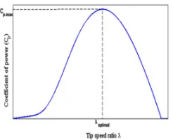
In this paper, the angle (β) is set to zero due to the assumption of fixed pitch wind turbine. Hence, the power coefficient mainly depends on the tip speed ratio. Fig.3 shows the characteristic of Cp as a function of . Based on that curve, there is only one optimal operating point, denoted by optimal, where Cp is maximum. To obtain the maximum power from the available wind the wind turbine should be operated at this point. Fig.4 presents the optimal operating point for various wind speeds.
[image:4.612.246.369.426.526.2]
Fig. 3 The characteristic of the power coefficient as a function of tip speed ratio
Fig.4.The characteristic of turbine power versus generator speed for various values of wind speed The amount of aerodynamic torque is obtained from the Pm.
Tm= (8)
Where, Tm is the mechanical power in N-m.
Technology (IJRASET)
III. PMSG MODEL
In order to design the PM machine in Matlab/Simulink is necessary to develop the mathematical model of the machine that is derived from the space vector form of the stator voltage equation.
Vabc=RsIabc+ φabc (9)
Where Rs is the stator winding resistance per phase, Iabc is the stator phase current, Vabc is the stator phase voltage and φabc is the flux linkage.
The dynamic model is derived in dq reference frame were q axis is rotating with 90o ahead to the d axis with respect to the direction of rotation. Based on the reference frame theory, stator voltage equations in dq synchronous reference frame are presented:
vd = Rs id+ φd –ωeφq (10)
vq = Rs iq+ φq +ωeφd (11)
Where vd, vq are the dq axis stator voltage, id, iq are the dq axis stator current, φd,, φq are the dq axis flux linkages, Rs stator resistances and ωe is the electrical speed in rad/s. Flux linkage equations are expressed as φd = Ldid + φm , φq = Lqiq. With Ld=Lq=Ls dq axis inductances and φm permanent magnet flux linkage. With the help of flux linkage equations, stator voltage equations in dq reference frame have the fallowing form:
= − +ωi (12)
= − − ω (i + ) (13)
Fig.5 d-axis equivalent circuit Fig.6. q-axis equivalent circuit
The electromagnetic torque equation is given by
Te= P (φmiq + (Ld – Lq) iqid) (14)
As the inductances on the d- and q-axis are equal, the electromagnetic torque can be regulated by iq as
Te = p φmiq (15)
The mechanical equation of the machine is express as a function of the electromagnetic torque (Te), load torque (Tm) and electrical velocity of the machine:
Te = Tm+B ωm+J ωm (16)
Where J is the moment of inertia and B is the viscous friction.
IV. POWER ELECTRONIC CONVERTERS
A. Three Phase Diode Bridge Rectifier
Rectification is the process of conversion of alternating input voltage to direct output voltage. A rectifier converts ac power to dc power. In diode based rectifiers, the output voltage cannot be control. For high power applications and where three phase power supply is available, a three phase bridge rectifier should be used. The diode rectifier is the most simple, cheap and rugged topology used in power electronic applications. The disadvantage of this diode rectifier is its disability to work in bi-directional power flow. The average output dc voltage from this rectifier can be obtained from Eq. (17), where the overlap due to the internal inductance of the PMSG is ignored.
Averageoutpuvoltage = Vml = √ Vl = √ Vp (17)
Vp = rms value of phase voltage.
B. Boost Converter
A boostconverter (step-up converter) is a DC-to-DC power converter with an output voltage greater than its input voltage. It is a class of switched-mode power supply (SMPS) containing at least two semiconductors and at least one energy storage element, a capacitor, inductor, or the two in combination. Filters made of capacitors (sometimes in combination with inductors) are normally added to the output of the converter to reduce output voltage ripple. In this model the boost converter is used to control the generator speed to operate the system at maximum power point by changing its duty cycle.
Fig.7. Boost converter schematic
The output voltage of the boost converter in terms of input voltage and duty cycle is given by
vo= (18)
The above expression shows that the output voltage is always higher than the input voltage (as the duty cycle goes from 0 to 1), and that it increases with D, theoretically to infinity as D approaches 1. This is why this converter is sometimes referred to as a step-up converter.
V. OTSR MPPT TECHNIQUE (PROPOSED METHOD)
An optimal TSR for maximum power extraction is inferred by relating the time taken for the disturbed wind to re-establish itself to the time required for the next blade to move into the location of the preceding blade. The block diagram of OTSR method is shown in fig. 8.
V tw + ω
ts -
ω
Fig.8. Block diagram of OTSR MPPT technique
For an n bladed rotor, the time period for the blade to move to its predecessor’s position is given by
ts= (19)
The time taken for the disturbed wind to re-establish itself (tw) given as:
tw= (20)
If (ts > tw), then some wind is unaffected. If (tw > ts), then some wind is not allowed to flow through the rotor. The maximum power extraction occurs when tw = ts. According to the equations (19), (20) and (4) an optimal tip speed ratio is expressed as
opt= (21)
Where, n is the number of blades.
For three bladed wind turbine the optimal tip speed ratio is 4.188. In real time, the optimal tips speed ratio can be calculated by
opt=2ωt (22)
R/2V
FLC
Wind Energy
System
Technology (IJRASET)
Fig.9. Flowchart for OTSR MPPT technique
The optimal tip speed ratio depends on the number of blades of the wind turbine. The wind turbine is modelled by replacing v by tw. If the aerofoil is designed with care, the optimal tip speed ratios may be about 25-30% above these optimal values. These highly efficient aerofoil rotor blade designs increase the rotational speed of the blade rotor therefore generating more power.
VI. FUZZY LOGIC CONTROLLER
Fuzzy logic control is a new addition to control theory. Its design philosophy deviates from all the previous methods by accommodating expert knowledge in controller design. FLC is one of the most successful applications of, fuzzy set theory. Its major features are the use of linguistic variables rather than numerical variables .Linguistic variables, defined as variables whose values are sentences in a natural language (such as small and large), may be represented by fuzzy sets. FLC’s are an attractive choice when precise mathematical formulations are not possible
Fig.10. Basic structure of fuzzy logic controller A. Fuzzification
It is a process of transforming a classical set into fuzzy set or it is a process of translating an uncertain event into fuzzy set by assigning a proper membership function or it is a process of transforming a scalar value into a fuzzy value. The membership function values are assigned to the linguistic variables using seven fuzzy subset for input variable and five subset for output variable. The triangular membership function is used for both variables.
Fig.11. Membership function of input variable
B. Fuzzy Inference Engine
These are the types of the method with the rule base so as to obtain the fuzzy values. There are basically two methods, such as Mamdani and Sugeno method. In this work Mamdani’s method is used with Max-Min operation fuzzy combination. Fuzzy inference is based on fuzzy rule base system. Rules are framed in inference engine block. The commonly used method is MAX-MIN. The output membership function of each rule is given by MIN (Minimum) operator and MAX (Maximum) operator.
C. Knowledge Base Or Rule Base
Fuzzy control rules are obtained from the analysis of the system behaviour. In their formulation it must be considered that using different control laws depending on the operating conditions can greatly improve the converter performances in terms of dynamic response and robustness. The control rules that associate the fuzzy output to the fuzzy inputs are derived from general knowledge of the system behaviour. A typical rule can be written as follows.
If input is NB then output is ZE
To obtain the control decision, the max-min inference method is used. It is based on the minimum function to describe the AND operator present in each control rule and the maximum function to describe the OR operator.
D. Defuzzification
The output of fuzzy controller is a fuzzy subset. As the actual system requires a non-fuzzy value of Control, defuzzication is required. Defuzzifier is used to convert the linguistic fuzzy sets back into actual value. There are five methods for defuzzification: Centroid method, Bisector method, Middle of Maximum, Smallest of Maximum, Largest of Maximum. The most commonly used method among all is the centroid method. For symmetrical figure such as triangular, square, centroid lies at the centre. For complex objects the overall centroid is calculated by breaking it into smaller objects using a weighted average (by area).
Cx =∑CixAi ∑Ai
Ci = Centroid of respective figure Ai = Area of respective figure.
VII. SIMULATION RESULTS
The wind turbine model is implemented by the following equation, which is derived from the equations (5) and (20).
Pm= R5Cp / (tw)3.
The Simulation diagram for wind turbine is shown in fig.13. Wind turbine model inputs are rotor radius, wind speed, generator tip speed and output is mechanical torque. The MPPT controller model and the overall simulation diagram of the proposed system are shown in fig.14 and fig.15. The system parameters are listed in table 1.
Fig.13. Simulation diagram for wind turbine Fig.14. Simulation diagram for MPPT controller
Technology (IJRASET)
TABLE 1
THE PROPOSED SYSTEM PARAMETERS
Parameters Symbol Value and Units
Rotor radius R 25m
Cut-in wind speed V 5m/s Cut-out wind speed V 25m/s
Optimal TSR opt 4.188 Power coefficient Cp 0.45
Air density ρ 1.237kg/m3 Stator Resistance Rs 4.34ohm Armature Inductance Ls 0.000515H
Generator Inertia J 0.00062kg.m2
Pole Pairs P 34
Boost converter inductance L 100Mh Boost converter capacitance C 150μF Load Resistance RL 100ohm Switching frequency f 5KHZ
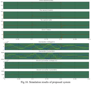
The simulation output waveforms of the proposed system are shown in fig.16. When the wind speed is14m/s, the generator tip speed is 2.35rad/sec, tip speed ratio is nearly 4.188 and the error value is maintaining at zero. The generator output voltage is 5500v and the boost converter output voltage is 10KV. The wind speed is increased to 18m/s the tip speed not increased to the exact value to maintain the error value zero when the FLC is not present. If FLC is present the tip speed increased to exact value by changing the boost converter duty cycle. Therefore the error value is maintaining at zero. The generator and boost converter output voltages are increased. The wind speed is decreased to 10m/s the tip speed, generator and boost converter output voltages are decreased. The simulation results are obtained with FLC.
Fig.16. Simulation results of proposed system
VIII. CONCLUSION
©IJRASET 2015: All Rights are Reserved
450
system. The system supplies to a resistive load through diode bridge rectifier and boost converter. The proposed wind energy conversion system was designed and simulated in Matlab/Simulink R2013a. The MPPT algorithm is implemented by using the fuzzy logic controller due to its advantages like Very robust, easily modified, use multiple inputs and outputs sources, simpler than its predecessors (linear algebraic equations), very quick and cheaper to implement. The combination of diode bridge rectifier and boost converter increase the system reliability. The simulation results have shown the proposed system performance.REFERENCEES
[1] Abdullah M.A., Yatim A.H.M., Tan C.W., Saidur R. (2012), "A review of maximum power point tracking algorithms for wind energy systems” Renewable and Sustainable Energy Reviews 16, 3220– 3227.
[2] Adinda Ihsani Putri, Minho Ahn, and Jaeho Choi1 (2014), “Speed Sensorless Fuzzy MPPT Control of Grid-Connected PMSG for Wind Power Generation”, School of Electrical Engineering, Chungbuk, 361-763.
[3] Brahmi J., Riches L., Ouali A. (2009), “A comparative study between three sensor less control strategies for PMSG in wind energy conversion system” Applied Energy; 86:1565–74.
[4] Changliang Xia, Zhiqiang Wang, Tingna Shi, and Zhanfeng Song (2013), “A Novel Cascaded Boost Chopper for the Wind Energy Conversion System Based on the Permanent Magnet Synchronous Generator” IEEE Transactions On Energy Conversion, Vol. 28, No. 4.
[5] Chia-Nan Wang, Wen-Chang Lin, and Xuan-Khoa Le (2014), “Modelling of a PMSG Wind Turbine with Autonomous Control”, Hindawi Publishing Corporation, Article ID 856173.
[6] Hui J., Bakhshai A. (2008), “A new adaptive control algorithm for maximum power point tracking for wind energy conversion systems” IEEE Power Electronics Specialists Conference PESC. p. 4003–7.
[7] J. S. Thongam, P. Bouchard, R. Beguenane, A. F. Okou, and A. Merabet, (2011), ” Control of Variable Speed Wind Energy Conversion System using a Wind Speed Sensorless Optimum Speed MPPT Control Method”, PowerEnerSys Inc., Chicoutimi, QC, Canada.
[8] Kazmi SMR, Goto H, Hai-Jiao G, Ichinokura O (2011), “A novel algorithm for fast and efficient speed-sensor less maximum power point tracking in wind energy conversion systems” IEEE Transactions on Industrial Electronics;58:29–36.
[9] Li S., Haskew T.A., Xu L. (2010), “Conventional and novel control designs for direct driven PMSG wind turbines” Electric Power Systems Research; 80:328–38.
[10] Mena Lopez H.E. (2007), “Maximum power tracking control scheme for wind generator systems” Texas A&M University.
[11] Molina M.G., dos Santos E.C., Pacas M. (2010), “Advanced power conditioning system for grid integration of direct-driven PMSG wind turbines” IEEE Energy Conversion Congress and Exposition. p. 3366–74.
[12] Muyeen S.M., Takahashi R., Murata T., Tamura J. (2010), ”A variable speed wind turbine control strategy to meet wind farm grid code requirements” IEEE Transactions on Power Systems;25:331–40
[13] NameyAli, Aziz Ahmad (2014), “Performance Analysis Of Operation And Control Of PMSG Based Grid Connected Variable Speed Wind Energy Conversion System Using SVPWM”, International Journal of Research in Engineering & Advanced Technology, Vol. 2, ISSN: 2320 – 8791.
[14] .N.S.Cetin, M.A Yurdusev, R.Ata and A.Ozdemir (2005), “Assessment of optimum tip speed ratio of wind turbines” Mathematical and computational applications, vol.10, no.1, pp.147-155.
[15] Phlearn Jansuya and Yuttana Kumsuwan (2013), “Design of MATLAB/Simulink Modelling of Fixed-Pitch Angle Wind Turbine Simulator” Energy Procedia 34, 62 – 370.
[16] Prerna Badoni, S. Bhanu Prakash (2014) “Modelling and Simulation of 2 MW PMSG Wind Energy Conversion Systems” IOSR Journal of Electrical and Electronics Engineering, vol.9, pp 53-58.
[17] Sanjiba Kumar Bisoyi, R.K.Jarial and R.A.Gupta (2014), “Modeling and Analysis of Variable Speed Wind Turbine equipped with PMSG” International Journal of Current Engineering and Technology, E-ISSN 2277 – 4106, P-ISSN 2347 – 5161.
[18] Shubham Khandelwal, Nikhil Bhugra, Ketan P Detroja (2014), “Controlled Power Point Tracking for Power Balancing in PMSG based Wind Energ y Conversion System”, Indian Institute of Technology, Hyderabad, India.
[19] S. N. Sivanandam, S. Sumathi and S. N. Deepa (2007), “Introduction to Fuzzy Logic using MATLAB” Springer-Verlag Berlin Heidelberg.
[20] S. Samanvorakij, P. Kumkratug (2014), “Modelling and Simulation PMSG based on Wind Energy Conversion System in MATLAB/SIMULINK” Proc. of the Second Intl. Conf. on Advances in Electronics and Electrical Engineering.
[21] T.Balamurugan, S.Manoharan (2012), “Fuzzy Controller Design using Soft Switching Boost Converter for MPPT in Hybrid System” International Journal of Soft Computing and Engineering ISSN: 2231-2307, Vol-3.
[22] Ying Zhu, Ming Cheng, Wei Hua and Wei Wang (2012), “A Novel Maximum Power Point Tracking Control for Permanent Magnet Direct Drive Wind Energy Conversion Systems”, Energies 5, 1398-1412.