6
I
January 2018
A Novel Approach to Control Single Phase
Induction Motor Using PIC18F4431
Latha L R1, D Satish Kumar2, Dr. Hari Priya 3
1
Assistant professor, Dept. of EEE, New Horizon College of Engineering, Bangalore, Karnataka, India1
2
Senior Assistant professor, Dept. of EEE, New Horizon College of Engineering, Bangalore, Karnataka, India2
3
Associate professor, Dept. of EEE, New Horizon College of Engineering, Bangalore, Karnataka, India3
Abstract: Single-Phase Induction motors are extensively used in appliances and Industrial controls. The permanent split capacitor (PSC) single-phase induction motor is the simplest and most widely used of this type. By design, PSC motors are unidirectional. By adding either extra windings, and external relays and switches, or by using gear mechanisms, the direction of rotation can be changed. When mechanical gears are used, the motor shaft runs in one direction, and the gears for forward and reverse engage and disengage according to the direction required. Using relays and switches, the polarity of the starting winding is electrically reversed based on the direction required. Unfortunately, all of these components increase the cost of the system for basic ON and OFF control in two directions. In this paper, the study is carried out to understand how to control the speed of PSC motor in both the directions using PIC18F4431 microcontroller and 3-Phase Inverter Bridge by PWM technique. The PIC18F4431 microcontroller-based control for PSC motor makes the system easy to implement and to have control over the motor in two directions. Implementing the algorithm using a 3-phase inverter bridge gives flexibility and efficiency of control. The PIC18F4431 is a popular low cost general purpose microcontroller from Microchip that can be used to implement the control algorithm.
Keywords: Permanent Split Capacitor (PSC) Motor, Pulse Width Modulation (PWM), PIC18F4431 microcontroller, 3-phase Inverter Bridge.
I. INTRODUCTION
This AC induction motors are the most common motors used in industrial motion control systems, as well as in main powered home appliances. Like most motors, an AC induction motor has a fixed outer portion, called the stator and a rotor that spins inside with a carefully engineered air gap between the two. There are probably more single-phase AC induction motors in use today than the total of all the other types put together because they are least expensive, lowest maintenance is required. To achieve better efficiency induction motor has to be controlled by some control techniques. Among different methods of control, Variable frequency drives serve the purpose to a good extent for low dynamic requirements. Even today it is commonly used for the open-loop speed control. Most single-phase induction motors are unidirectional. Using microcontroller-based control systems, one can add speed variation to the system. In addition to the option of speed variation, the direction of rotation can also be changed, depending upon the motor control algorithms used.
Among the types of Single phase induction motors available, PSC motors have several advantages. The motor design can be easily altered for use with speed controllers. They can also be designed for optimum efficiency and High-Power Factor (PF) at the rated load. This motor has higher starting torque than the split-phase type. They’re considered to be the most reliable, less expensive and require less maintenance compared to all other single-phase motors, mainly because no centrifugal starting switch is required. Hence in this paper, an attempt is made to generate the pulse width modulated signals to control PSC type single phase induction motor on both forward and reverse directions using PIC18F4431 microcontroller and 3-Phase Inverter Bridge.
II. LITERATURESURVEY
A. A New Induction Motor V/f Control Method Capable of High-Performance Regulation at Low Speeds
Alfredo Munoz et al. proposed a novel open-loop speed control method for induction motors. The control scheme is based on the
This provides high output torque and nearly zero steady-state speed error at any frequency. Also from the proposed method, the speed can be accurately controlled with higher values of load torque than the rated value.
B. A Review on Speed Control Techniques of Single Phase Induction Motor
Atul Gajare et al. described the speed control of single phase induction motor by means of frequency. Here, SPIM has been controlled by frequency control method by using PWM control circuit and H-bridge inverter. These MOSFET are used in H-bridge configuration to form inverter to supply AC current to the motor.
C. Optimization of Single-Phase Induction Motors—Part I: Maximum Energy Efficiency Control
Christos Mademlis et al. proposed a triac-based drive with an optimal efficiency voltage controller and an experimental procedure was followed for adjusting its parameters. The control scheme employed satisfies all of the prerequisites of simplicity, reliability, and cost-effectiveness that are imposed by the utilization of a single-phase motor.
D. Pwm Ac Chopper Control Of Single Phase Induction Motor For Variable Speed Fan Application
Deniz Yildirim et al. presented a variable speed control method in which a pulse-width-modulated (PWM) AC chopper technique is used to change the effective value of the supply voltage and is applied to a single-phase induction motor. This variable supply voltage gives the ability to control the speed of the motor. Harmonics generated by the speed control unit are altered by an input according to the limits using harmonic current emissions standards.
E. Adjustable-Speed Single-Phase IM Drive With Reduced Number of Switches
Miroslav Chomat et al. focused on the properties of a drive that uses a single-phase machine of permanent-split capacitor type to drive a fan-type load with variable mechanical speed. To generate the supply voltage with variable frequency a converter with the minimal number of active switches and diodes is used.
F. Development of Single Phase Induction Motor Adjustable Speed Control Using M68HC11E-9 Microcontroller
Senan Bashi et al. investigated the performance of single-phase induction motor using microcontroller M68HC11E-9. The microcontroller has been programmed to vary the pulse width variation that controls the duty cycle of the dc chopper. The inverter receives the dc signal from the chopper and converted to ac power to feed the motor. Speed’s feedback signal is sensed by the microcontroller and consequently pulse width variation signal is provided that sets the gate voltage of the chopper, which in turn provides the required voltage for the desired speed. Here, buck chopper has been used to control the input voltage of a fully controlled single phase isolated gate bipolar transistor (IGBT) bridge inverter. PWM technique has been employed in this inverter to supply the motor with ac voltage. The problem for this microcontroller was that it had no dead band register and only had a three PWM output.
III. METHODOLOGY
In scalar control, the motor is fed with variable frequency signals generated by the PWM control from an inverter using the feature rich PIC microcontroller. Here, the V/f ratio is maintained constant in order to get constant torque over the entire operating range. Since only magnitudes of the input variables – frequency and voltage – are controlled, this is known as “scalar control”. Generally, the drives with such a control are without any feedback devices (open loop control). Hence, a control of this type offers low cost and is an easy to implement solution. In such controls, very little knowledge of the motor is required for frequency control. There are number of ways to implement scalar control. In this project, the popular Pulse Width Modulation technique is used.
PWM stands for Pulse Width Modulation. This means that one can generate a pulse whose width (i.e., duration) can be altered. The PWM technique converts an analog input level into a variable duty cycle switch drive signal. There are number of ways to implement scalar control. In this project linear fixed PWM technique is used. Since microcontrollers live in a digital world then their output pins can be either low (0v) or high (5v). PIC microcontrollers have Analogue to Digitals Convertors (ADC) to convert a voltage from the analogue world to a number but to convert from Digital to Analog PWM technique is used.
each other. This enables the system designer to remove the capacitor, which is in series with start winding, from the circuit permanently—thereby reducing the total system cost.
A. Using H-Bridge Inverter
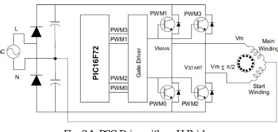
[image:4.612.166.447.169.303.2]This method has a voltage doubler on the input side; on the output side an H-bridge or two-phase inverter is used. One end of the main and start windings are connected to each half bridge; the other ends are connected together at the neutral point of the ac power supply, which also serves as the center point for the voltage doubler as shown in Fig.3.1.
Fig. 3.1: PSC Drive with an H-Bridge
The control circuit requires four PWMs with two complementary pairs and sufficient dead band between the complementary outputs. PWM0-PWM1 and PWM2-PWM3 are the PWM pairs with dead band. Using PWMs, the dc bus is synthesized to provide two sine voltages at 90 degrees out of phase with varying amplitude and varying frequency, according to the VF profile. If the voltage applied to the main winding lags the start winding by 90 degrees, then the motor runs in the forward direction. To reverse the direction of rotation, the voltage supplied to the main winding should lead the voltage supplied to the start winding.
This H-bridge inverter method of controlling a PSC type motor has following disadvantages.
1) The main and start windings have different electrical characteristics. Thus, the current flowing through each switch is unbalanced. This can lead to the premature breakdown of switching devices in the inverter.
2) The common point of the windings is directly connected to the neutral power supply. This may increase the switching signals
creeping into the main power supply, and may increase the noise emitted onto the line. In turn, this may limit the EMI level of the product, violating certain design goals and regulations.
3) The effective dc voltage handled is relatively high due to the input-voltage doubler circuit. 4) The cost of the voltage doubler circuit itself is high due to two large power capacitors.
A better solution to minimize these problems would be to use a three-phase inverter bridge, as discussed in the proposed technique. Another advantage of using the phase control method is that the same drive-hardware topology can be used to control a three-phase induction motor. In this scenario, the microcontroller should be reprogrammed to output sine voltages with 120-degree three-phase shift to each other, which drives a three-phase induction motor. This reduces the development time.
Single-phase induction motors are very popular in appliances, and industrial and consumer applications. PSCs are the most popular type of single-phase induction motors. Controlling the motor speed has many advantages, such as power efficiency, reduced audible noise and better control over the application.
IV. PROPOSEDCONTROLMETHOD
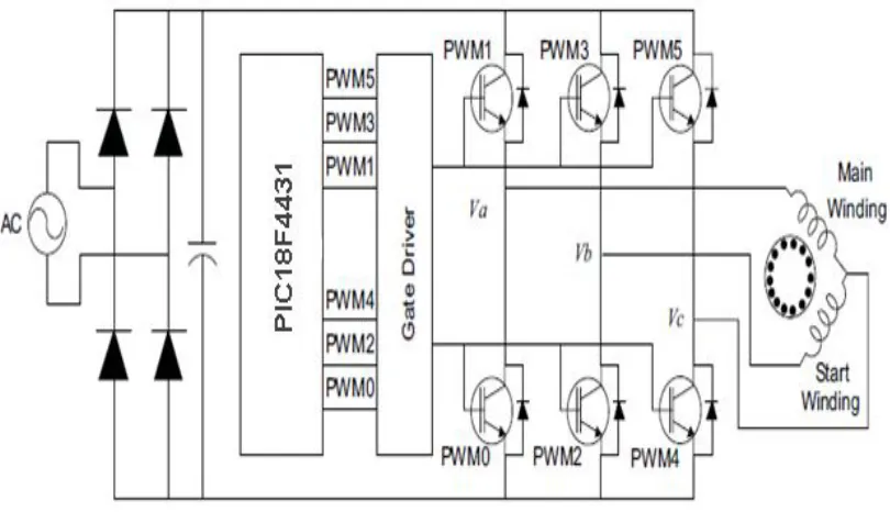
Fig. 4.1 Controlling a PSC motor with a 3-phase inverter bridge
3-phase bridge inverters are widely used for ac motor drives and general purpose ac supplies. The circuit consists of three half-bridges. It is a Variable Frequency Drive. The VFD is a system made up of active/passive power electronics devices (IGBT, MOSFET, etc.), a high speed central controlling unit (a microcontroller) and optional sensing devices, depending upon the application requirement. The basic function of the VFD is to act as a variable frequency generator in order to vary speed of the motor as per the user setting. The rectifier and the filter convert the AC input to DC with negligible ripple. The inverter, under the control of the microcontroller, synthesizes the DC into three-phase variable voltage, variable frequency AC. In this paper, one end of main winding and start winding are connected to one half bridges each. Other ends are tied together and connected to the third half bridge. With this drive topology, control becomes more efficient. The phase voltages Va, Vb and Vc should be controlled to
achieve the phase difference between the effective voltages across the main and start winding to have a 90 degree phase shift to each other. The PIC18F4431 belongs to the Mid-Range family of the PIC devices. PIC18F4431 is a 40 pin IC, chosen because it is one of the simplest and low cost general purpose microcontrollers Microchip has in its portfolio, that can be used to implement the control algorithm by the Pulse width modulated signals to control the switching operation of the inverter switches and hence to control the PSC motor on both the directions accordingly.
V. PWMGENERATIONUSINGPIC18F4431
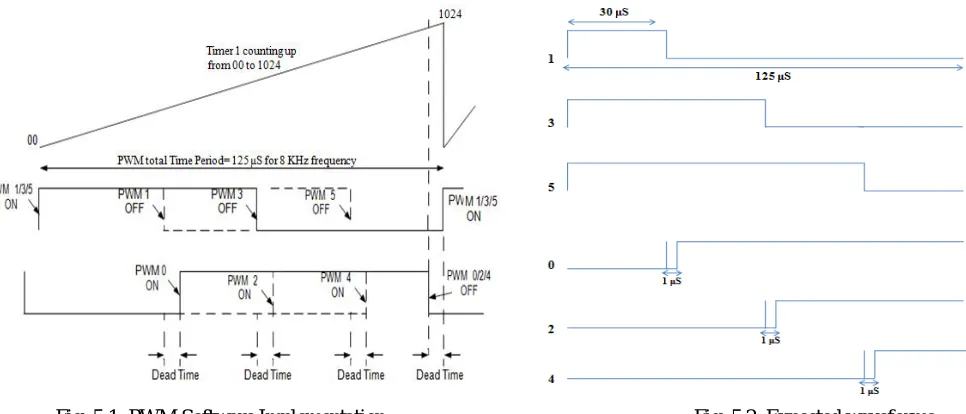
PWM can be achieved as shown in the fig.5.1 to control the PSC type of single phase induction motor. Corresponding expected waveforms are shown in fig.5.2. The switching frequency of the PWM is considered to be 8 KHz hence the total time period for each cycle of PWM will be around 125 μS. A dead time of around 1 μS is been included through software. Dead time is essential in
an induction motor control application to avoid cross conduction of the dc bus through the power switches when one turns OFF and the other turns ON.With the reference of expected waveforms shown in fig.5.2, one can divide each cycle of PWM into 4 intervals. Therefore each interval in every cycle will be approximately for 30 μS. Therefore each interval in every cycle will be approximately for 30 μS. PWM1 will be ON for 25% of the total time period i.e. for 30 μS and will be OFF for the remaining 75% of the total time
period. PWM0 is complementary to the PWM1 which will be OFF for 25% of the total time period and ON for the remaining 75% of the total time period. PWM3 will be ON for 50% of the total time period and will be OFF for the remaining 50% of the total time period. PWM2 is complementary to the PWM3 which will be OFF for 50% of the total time period and ON for the remaining 50% of the total time period.
Fig. 5.1: PWM Software Implementation Fig. 5.2: Expected waveforms
From the fig.5.1 switching action of the inverter switches can be done in the order below,
PWM 1/3/5 ON, PWM 1 OFF, PWM 0 ON, PWM 3 OFF, PWM 2 ON, PWM 5 OFF, PWM 4 ON, PWM 1/3/5 ON and cycle repeats.
VI. RESULTANDDISCUSSION
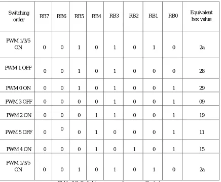
Implementation of PWMs can be achieved by using port B of PIC18F4431 microcontroller. PORTB is an 8-bit wide, bidirectional port. The corresponding data direction register is TRISB. Setting a TRISB bit (= 1) will make the corresponding PORTB pin an input. Clearing a TRISB bit (= 0) will make the corresponding PORTB pin an output. Out of 8 bits (RB0 to RB7) of port B, first 6 bits (RB0 to RB5) have been considered to generate the 6 PWMs required. It can be done as follows.
A. For Forward direction
If the status of the switch connected to the port C is read to be high, the motor rotates in the forward direction. The corresponding
switching actions are listed below. There should be a deadtime of 1μS between OFF and ON period of any switch.
Switching
order RB7 RB6 RB5 RB4 RB3 RB2 RB1 RB0
Equivalent hex value
PWM 1/3/5
ON 0 0 1 0 1 0 1 0 2a
PWM 1
OFF 0 0 1 0 1 0 0 0 28
PWM 0 ON 0 0 1 0 1 0 0 1 29
PWM 3
OFF 0 0 1 0 0 0 0 1 21
PWM 2 ON 0 0 1 0 0 1 0 1 25
PWM 5
OFF 0
0
PWM 4 ON 0 0 0 1 0 1 0 1 15
PWM 1/3/5
[image:7.612.115.497.76.164.2]ON 0 0 1 0 1 0 1 0 2a
Table 6.1: Switching sequence for forward Control
B. For Reverse direction
If the status of the switch connected to the port C is read to be low, the motor rotates in the reverse direction. The corresponding switching actions are listed below. To have the reverse rotation, any two phases of the motor must be interchanged. This can be achieved through PWM by reversing the duty cycles of any 2 pairs of switches. Here the periods of switches 2 and 3 are interchanged with the periods of switches 4 and 5 respectively. i.e. 50% ON, 50% OFF period of PWM3 is interchanged by 75% ON, 25% OFF period of PWM5 and 50% OFF, 50% ON period of PWM2 is interchanged by 75% OFF, 25% ON period of PWM4.
Switching
order RB7 RB6 RB5 RB4 RB3 RB2 RB1 RB0
Equivalent hex value
PWM 1/3/5
ON 0 0 1 0 1 0 1 0 2a
PWM 1 OFF
0 0 1 0 1 0 0 0 28
PWM 0 ON 0 0 1 0 1 0 0 1 29
PWM 3 OFF 0 0 0 0 1 0 0 1 09
PWM 2 ON 0 0 0 1 1 0 0 1 19
PWM 5 OFF 0 0 0 1 0 0 0 1 11
PWM 4 ON 0 0 0 1 0 1 0 1 15
PWM 1/3/5
ON 0 0 1 0 1 0 1 0 2a
Table 6.2: Switching sequence for reverse Control
C. Output Waveforms
[image:7.612.90.526.263.623.2]D. For Forward Direction
[image:8.612.87.527.97.207.2]a) At ADC=0 b) At ADC=27 c) At ADC=504
Fig. 6.3: PWM1 and PWM0 Waveforms
From the Fig. 6.3, note that width of each pulse in PWM1 and PWM0 is increased as ADC value is increased.
1) PWM3 and PWM2
[image:8.612.44.553.252.418.2]a) At ADC=0 b) At ADC=27 c) At ADC=504
Fig. 6.4: PWM3 and PWM2 Waveforms
From the Fig. 6.4, note that width of each pulse in PWM3 and PWM2 is increased as ADC value is increased.
2) PWM5 and PWM4
a) At ADC=0 b) At ADC=27 c) At ADC=504
Fig. 6.5: PWM5 and PWM4 Waveforms
From the Fig. 6.5, note that width of each pulse in PWM5 and PWM4 is increased as ADC value is increased.
[image:8.612.43.553.461.662.2]E. For reverse direction 1) At ADC=0
Fig. 6.6: Comparison of PWM2 and PWM3 with PWM4 and PWM5 at ADC=0
To achieve Reverse rotation of motor, the periods of switches 2 and 3 are interchanged with the periods of switches 4 and 5 respectively. i.e. 50% ON, 50% OFF period of PWM3 is interchanged by 75% ON, 25% OFF period of PWM5 and 50% OFF, 50% ON period of PWM2 is interchanged by 75% OFF, 25% ON period of PWM4 as shown in the fig.6.6.
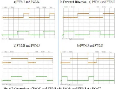
[image:9.612.132.516.399.699.2]2) At ADC=27
Fig. 6.7: Comparison of PWM2 and PWM3 with PWM4 and PWM5 at ADC=27
3) At ADC=504
Fig. 6.8: Comparison of PWM2 and PWM3 with PWM4 and PWM5 at ADC=504
From the waveforms, notice that the pulse width of all the PWMs will increase by increasing the ADC value and here the duty cycles of PWM2 and PWM3 are interchanged with the duty cycles of PWM4 and PWM5 respectively to have the reverse rotation. Hence the variable speed control of a PSC type of single phase induction motor in reverse direction can be achieved by giving these pulses to the 3 phase inverter to have desired switching action.
VII. CONCLUSION
The PIC18F4431 is a popular low cost general purpose microcontroller from Microchip that can be used to implement the control algorithm. The PIC18F4431 microcontroller-based control for PSC motor makes the system easy to implement and have control over the motor in two directions. Implementing the algorithm using a 3-phase inverter bridge gives flexibility and efficiency of control. Here the plus point is that, the motor can be rotated in two directions. So that it can be used in all the applications in which the operation in both directions is needed. Here Programming has been done to generate the PWMs required to control the three phase inverter and hence to control the PSC type of single phase induction motor. All the set of waveforms are provided in the Results section for both forward and reverse operations. Waveform clearly shows that the motor can be operated and controlled in both the directions for the variable speeds depending on the ADC value. ADC value can be varied by varying the potentiometer. Direction of rotation can be changed by the usage of switch.
REFERENCES
[1] Alfredo Mu˜noz-Garc´ıa, Thomas A. Lipo, Fellow, IEEE, and Donald W. Novotny, Fellow, IEEE “A New Induction Motor V/f Control Method Capable of High-Performance Regulation at Low Speeds”
[2] Atul M. Gajare1, Nitin R. “A Review on Speed Control Techniques of Single Phase Induction Motor” International Journal of Computer Technology and Electronics Engineering (IJCTEE) Volume 2, Issue 5, October 2012
[3] Christos Mademlis, Member, IEEE, Iordanis Kioskeridis, and Theodoros Theodoulidis, Associate Member, IEEE “Optimization of Single-Phase Induction Motors—Part I: Maximum Energy Efficiency Control”
[4] Deniz Yildirim and Murat Bilgic “PWM AC chopper control of Single phase induction motor for variable speed fan appliction” IEEE 2008
[5] Maurício Beltrão de Rossiter Corrêa, Member, IEEE, Cursino Brandão Jacobina, Senior Member, IEEE, Edison Roberto Cabral da Silva, Fellow, IEEE, and Antonio Marcus Nogueira Lima, Member, IEEE “Vector Control Strategies for Single-Phase Induction Motor Drive Systems”
[6] Miroslav Chomat, Member, IEEE, and Thomas A. Lipo, Fellow, IEEE “Adjustable-Speed Single-Phase IM Drive With Reduced Number of Switches” [7] Senan M. Bashi, I. Aris and S.H. Hamad “Development of Single Phase Induction Motor Adjustable Speed Control Using M68HC11E-9 Microcontroller”,