5
X
October 2017
Investigation of Heat Transfer Rate through
Porous Material
S. V. Vanjari1, S. M. Mane2, A. A. Asolkar3
1
Professor, Department of Mechanical Engineering, SSPM’s College of Engineering, Kankavli
2, 3
UG Students, Department of Mechanical Engineering, SSPM’s College of Engineering, KankavliUniversity of Mumbai, India
Abstract: The present experimental work is done to investigate forced convective heat transfer rate through porous material. For this study stainless steel ball of diameter 8, 12 and 16 mm are used to form test section with different porosity. The different parameters are calculated like Reynolds number, Prandtl number, porosity, convective heat transfer coefficient and plotted the effects of porosity and mass flow rate on heat transfer rate. It shows that for minimum porosity heat transfer rate increases and it depends upon mass flow rate also.
Keywords: Heat transfer, porous material, porosity, rate of heat transfer, convective heat transfer enhancement.
I. INTRODUCTION
Heat transfer through porous material has a great scope in chemical, mechanical, aerospace, medical, biological engineering, materials sciences & many more fields. Due to increase in contact surface with fluid and efficient heat transfer property, Porous material being a part of interest of many researches. Number of Experiments, analytical work, researches has been done to investigate heat transfer phenomena through porous materials such as sintered metals, foams (metal or polymeric), ceramics, etc. Recent advances in electronic system, heat exchangers, chemical reactors, etc; have lead to dramatic increases in heat flux. Heat transfer through porous media is being explored to thermal management of such systems. Many studies & experimental work have reported that Heat transfer through porous media is more efficient techniques than traditional one.
A. Porosity
A porous medium is a material which contains pores or voids in it. These pores are typically filled with a liquid or gas. Because of pore size, large surface contact area and flexible frameworks porous material enhances heat transfer. The skeletal material is usually a solid, but foams are also analysed using concept of porous media.
Porous mediums reduce the thermal resistance at the gas/solid interface and enhance heat transfer rates. Porosity (ϕ) is defined as a
ratio of total pore volume (VP) to the apparent volume of the particle or powder. Φ= VP/ V Porous materials can be grouped into three classes based on their pore diameter (Ø), pore sizes in the range of 2 nm and below are called microspores, those in the range of 2 nm to 50 nm are denoted mesoporous, and those above 50 nm are macrospores
II. LITERATUREREVIEW
Heat transfer through porous medium was extensively investigated in the past decades by lots of researches and scholars. The current study is the idea based on the literature survey as discuss below. As surface area increases with flowing fluid, heat transfer rate also increases, these phenomena became the attention point of many researchers. Forced convection heat transfer over a porous horizontal flat plate made up of three different materials i.e. glass, rock and steel have been experimentally investigated by S.E. Mahgoub [1]. Sheng-Chung Tzeng et al [2], concluded that for a constant flow-rate, as the porosity decrease, contact surface of the fluid increases, causes a higher heattransfer rate between the fluid and the solid phases. Different porous material with different porosity have been studied for many applications like roof surface temperature moderation [3], cooling of high-power mini-devices [4], enhancing heat transfer rate in Heat exchangers[5,6], cooling of high-powered microprocessors [7]. Bo Yan et. al.[8], used porous media in liquid piston to improve the performance of compression and expansion processes. Effect of pore structure is also key factor to study performance of porous metal fiber materials [9].
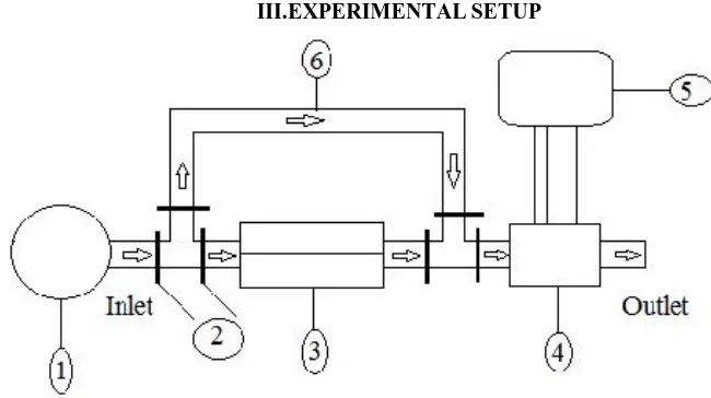
III.EXPERIMENTALSETUP
Figure 1: Block Diagram of Experimental set-up
1. Air Blower 2.Flow control valves 3.Electric Heater 4.Test Section 5. Data Recording System 6.Pipe Arrangement
The experimental set up for investigation of heat transfer rate in the porous material is shown in Fig. 1. It consists of an air flow circuit, a test section, electric heater, flow meter, and temperature sensor. In the present study, air will be induced to the wind tunnel by a centrifugal suction blower and the inlet temperature is read by a thermometer. Before entering the test section, the air flow will be heated by passing through a removable electric heater and then transverses the test section, where the particles inside will be heated by the hot air. When the test section temperature will be stabilized, the atmospheric air will be passed into the channel and test section is cooled down until its temperature decreases to the ambient temperature. During the cooling process, the experimental data will be measured and recorded simultaneously. The volumetric flow rate through the test section will be measured by a flow meter, which will be situated at the downstream of the test section. The static pressure difference across the test section will be displayed by a micro-differential meter combined with inclined manometer. The air flow and particle temperatures will be measured by PT100 thermocouple
A. Test Section
As shown in Fig.2, the test section is made of Acrylic Sheet plates (thickness of 10mm) and stainless steel balls are orderly stacked inside. In present study, the test section is composed of 100mm X 50mm X 50mm packed cells, which would guarantee the fully developed flow and heat transfer inside. Three different diameters are used to maintain different porosity. 8mm, 12mm and 16mm balls are used with SC structure.
Figure 2: Block Diagram of Test Section
IV.METHODOLOGY
After manufacturing experimental set-up as shown in fig.1 and different test section of different porosities as shown in fig 3, investigation is started. In this experimental work mass flow of air and porosity of test section is variable.
First insert the test section made up of 8mm diameter stainless steel ball, heated up to steady state conditions and then cool it by using atmospheric air. Here the same test section is allowed to cool with 200lph, 400lph and 600lph mass flow rate of air and reading is noted down.
Same procedure is followed for next test section and readings are recorded which are plotted on graph.
V.RESULT AND DISCUSSION
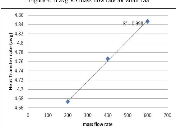
The heat transfer rate is calculated for three test section having different porosities and different mass flow rate viz; 200lph, 400lph and 600 lph. The following graphs show the relation between average convective heat transfer rate and mass flow rate for different test sections.
[image:4.612.175.429.262.463.2]is observed that as mass flow rate of air is increased, heat transfer rate is increased also the maximum heat transfer rate is getting for low porosity.
[image:4.612.163.446.484.693.2]Figure 4: H avg VS mass flow rate for 8mm Dia
Figure 6: Porosity VS H avg for 200lph
Figure 7: Porosity VS H avg for 400lph
Also the relation between porosity and heat transfer rate for different mass flow rate is shown in the following graphs.
It has been noticed that the heat transfer rate is increased with decreased in porosity as surface contact between fluid and solid is increases. The pressure drop also changed as porosity of test section is changed, but it is observed that there is very small variation in pressure drop for all of three test section.
REFERENCES
[1] S.E. Mahgoub,(2013), “Forced convection heat transfer over a flat plate in a porous medium,” Ain Shams Engineering Journal, vol.4, pp. 605-613.
[2] J. Breckling, Ed., The Analysis of Directional Time Series: Applications to Wind Speed and Direction, ser. Lecture Notes in Statistics. Berlin, Germany: Springer, 1989, vol. 61. Sheng-Chung Tzeng, Wen-Yuh Jywe, Chu-Wei Lin, Yen-Chan Wang, (2005), “Mixed convective heat-transfers in a porous channel with sintered copper beads,” Elsevier, Applied Energy, 81, pp. 19-31. Surakha Wanphen, Katsunori Nagano, (2009), “Experimental study of the performance of porous materials to moderate the roof surface temperature by its evaporative cooling effect,“ Elsevier, building and environment, 44, pp. 338-351. [3] G. Hetsroni, M. Gurevich, R. Rozenblit., (2006), “Sintered porous medium heat sink for cooling of high-power mini-devices, “ Elsevier, International Journal
of Heat and Fluid Flow, 27 pp. 259-266.
[4] Bogdan I. Pavel, Abdulmajeed A. Mohamad,(2004), “An experimental and numerical study on heat transfer enhancement for gas heat exchangers fitted with porous media,” Elsevier, International Journal of Heat and Mass Transfer, 47, pp. 4939–4952.
[5] (2002) The IEEE website. [Online]. Available: http://www.ieee.org/
[6] Pei-Xue Jiang , Ming-Hong Fan, Guang-Shu Si, Ze-Pei Ren,(2001), “Thermal±hydraulic performance of small scale micro-channel and porous-media heat-exchangers,” pergamon, International Journal of Heat and Mass Transfer, 44, pp. 1039-1051.
[7] Randeep Singh, Aliakbar Akbarzadeh, Masataka Mochizuki,(2009), “Sintered porous heat sink for cooling of high-powered microprocessors for server applications,” Elsevier, International Journal of Heat and Mass Transfer, 52, pp. 2289–2299.
[8] Bo Yan , Jacob Wieberdink, Farzad Shirazi , Perry Y. Li, Terrence W. Simon, James D. Van de Ven,(2015) “Experimental study of heat transfer enhancement in a liquid piston compressor/expander using porous media inserts,” Elsevier, Applied Energy, 154, pp. 40-50.
[9] Tang Huiping, Wang Jianzhong, Ao Qingbo, Zhi Hao, (2015), “Effect of Pore Structure on Performance of Porous Metal Fiber Materials,” sciencedirect, Rare Metal Materials and Engineering, volume- 44, pp. 1821-1826.
[10] Pengfei Xu, Qiang Li, Yimin Xuan, (2015), “Enhanced boiling heat transfer on composite porous surface,” Elsevier, International Journal of Heat and Mass Transfer, 80, pp. 107-114.