STARAN S
APPLE
Programming
Manual
Price
$
25. 00
GOODYEAR AEROSPACE
CORPORATION
AKRON, OHIO 44315
STARAN S APPLE PROGRAMMING MANUAL
NOTICE
This document contains material generated by Goodyear Aerospace Corporation and is transmitted for the purpose of aiding the transaction of business between Goodyear Aerospace Corporation and the recipient.
It is understood that the material contained herein will not be used, copied, or disclosed to others, without specific written consent of Goodyear
Aerospace Corporation.
APPLE UPDATING
The Associative Processor Programming Language (APPLE) continues to be improved and expanded. Interested parties should contact Goodyear Aerospace Corporation, Computer Division Marketing, Akron, Ohio 44315, Telephone: (216) 794 -3631 for information regarding the latest update of APPLE.
LIST OF EFFECTIVE PAGES
Insert latest changed pages and dispose of superseded pages.
NOTE: On a changed page, the portion of the text affected by the latest change is indicated by a vertical line in the outer margin of the page. Changes to illustrations are indicated by miniature pointing hands. A zero in the change number column indicates an original page.
The total number of pages in this manual is 247, consisting of the following:
Page Change
No. Number
Title.
a
A.
a
i - v i
a
1-1
-
1-3a
CHAPTER
2
TABLE OF CONTENTS
TITLE
INTRODUCTION
.
.
.
.
. .
. .
. .
.
.
. . .
.
. .
. . .
. . .
.
. . . .
.
.
. .
General.
.
.
.
. . .
. .
.
.
. . .
.
. . . .
.
.
.
.
.
.
.
.
.
APPLE.One- To-One One - To-Many.
In Line
Subroutine Call Sequence. Assembler Directives ••
Comment Statements APPLE Features ••
PAGE 1-1 1-1
1-2
1-2
1-2
1-2
1-2
1-2
1-2
1-2
QUICK INDEX OF APPLE INSTR U CTlON G ROUPS ~:;:;:;:;:;:;:;:;:;:;:;:;:::::::;:::::;:;:::::;:;:;=::;=;=;=;=;=;=;:;:::;:;:::;:;;;:;:::;;;:;:;;:::;:;;;;;;;;:::;:;;: 2 - i
APPLE LANGUAGE STRUCTURE. Source Statements.
Label Field Command Field. Argument Field • Comment Field Required Entries Summary
Language Elements Character Set • Symbols • • •
Symbol Table • Constants
Octal Constants •• Decimal Constants Hexadecimal Constants. Expressions • • •
Examples. Location Counters ••
Load Location Counter • Execution Location Counter Location Counter Symbol ($) •
Addre s sing. • • • • • •
Control Memory Address • • • • • • •
Associative Memory or Common Register Field Expression •
1
2
Example 1 Example 2 Assembler Directives.
CHAPTER
2 (cont)
3
TABLE OF CONTENTS
TITLE
Branch Instructions • . . . • . . • . . . . • • • • • . . . • • . • • . . . • . . • . • • . . • . • . . • . .
Register Instructions • . . • . . . . • . . . • . . . . • . • . . . • • . • . . . • • • • • . • • • • . • .
As sociative Instructions ••..•....•..•.••••...•.•..•.••..••..••••••. Loads . . . • . . . • . . • • . • . • . • • • • . • • • . . . • • . • • • • • . • . . . • . . • . . Stores • • . . . • • . . • . . • . • . . • • . . . • . . • . . . . • . . • . • . . • • • • . • . . • . • . • • • . • Searches . . . . • . . . . • . • . . • . . • . • . • . . . • • . . . . • . • . . . • . . • • . . Moves ••....••.•..•.•..•....••.•.•...•..•..•.••••••••••. Arithmetics • . . . • • . . . • . . • . • . . . • . . . • . . . . • . . .
Control and Test • . . . • • . . • . . . • . . • . . . . • . . . • . . • . . • . • . . • . . • . • .
Pager Instructions . • . . . • . . . • . . . . • . • . . . • . . • • • . . . • . •
SUPERVISOR CALLS • . . . . • . . • . . . . • . • • . • . . • . . . • • • . . . . • . • . . . . • . . • • . • • . . .
PAGE
2 -17
2-35
2-55 2-55 2-79 2-108 2 -125 2-138
2-154
2-159
3-1
Introduction . . • • . • . . • . . • . . . • • • . • . . • . . • . • . . . • . . . • . • • • . . . . • • 3-1
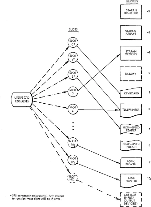
Slot Numbers 3-1
Device As signment Table (DAT) . • • . . . . . • . . • • . . . • . • • . • . . • . . • . • • 3-2
CHAPTER
3 (cont)
APPENDIX
A
B
C
D
E
F
G
TABLE OF CONTENTS
TITLE PAGE
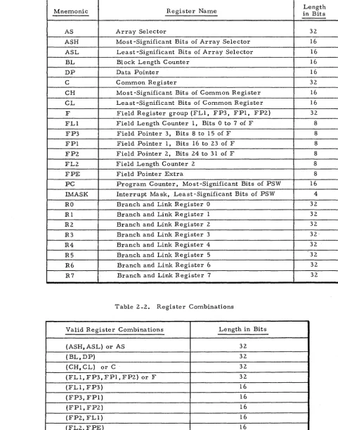
STARAN Registers. . . • . . • . . . . • . . . • • . • . . . • 3 -12
Format. . • . • . . • . . . • . . . • . . • . . . . • . . . • . . . . 3 -12
Buffer Format For Device -3 .•..•. . . . • . . . . . . . 3-13
Example. • . . • . . . • . . • . • • . • • • . . • . . . • . . • . . . • 3 - 14
Read. . .. . . . . • . .. . . . •••. . .. .• .. .. . . .• . . .• . . . • .. . ..• .••. •.• . .• •• 3-15
Format . . . . • . . . • . . . . • . . . . • . . • • . . . . • . • . . • . . . . • . . . 3 -15
Example . . . • . . • . . . . • • . • . . . • • . • • . . • . . • • • . • . . • • . . . • 3 -15
Write. . • . . • • . • . . • . • . . . . • • . . • . . . • . . . . • . . • . . . • • . . . . • • . • . . . . • . . . • 3-16
Format . • . • • • . • . . . • . • • . . . • . . . • . . . • • . • . . . . • . . . • 3 -16
Example • • • . . • . . • . • . . • . . • . . . • . . • . . • . . . . • • . . . • . . • 3 -16
Read/Write BUFFER Pseudo-op • . . . • • . . . • • . . . . • . . • . . . • 3-17
Format. •. . • •. • . .. . •. . . . ••. .• . . . . .. • . .•• ... •. . ...•. •. .• .•. . 3-17
Example • • • . . • . . • . • • . . . • . . . . • . . . • • . • • . . • 3 -19
Restart Program. • . . . . • . . . • • . . . • . . • . • • . . . 3 -21
Reset Peripheral Devices ••... '. . . .•.. .. . . ... . •. •• . . .• 3-22
Free Device For New Task. .• . . . . . .. . . . •. . . . .•. ... .. . . . •.. . . . •. . 3-23
Exit to Supervisor • . . . • . . • . . • . . . • • . . . • • . . • . . • . . . • . 3 -24
Timer Start . . . • . . . • . • . . • . . • . . . . • • . . . . 3-25
Int - Signal Sequential Processor Interrupt . • . . . • . . . • . • . . • . . • . . . 3-26
Isetup - Setup Interrupt. • . . . . . . . . • . . • • . . . • . . • . . • . • . • • . • • . • . • 3-27
Pager Control. • • . . • . • . . . • . . . • • . . . • . . . • . • . . • . • . . • . . . • . • . . . 3 -2 8
PI/O Control. • . . . • . • • . . . • . . . • . . • • • • • . • • • • . • . • • . • . . • . • . . • • • • 3 -29
TITLE PAGE
SUMMARY OF APPLE MNEMONICS AND INSTRUCTION FORMATS... A-i ERROR CODES . . • . . . . • . • . . . • . • . • • . • • . . . . . • . . • . . • . . . • . . . • . • • • • . • • . . . • B-i TERMS AND S y M B O L S . . . C-i HEXADECIMAL/DECIMAL TABLE. . • . . • . . • . . . • • . • . . . • . . • • . • . . . • . . . D-i OCTAL/DECIMAL. •.•.. •. . . .• . .•. ••.•. . •. ••.•. . . .. . . .. .. . . •.•. . . . •. E-i POWERS OF TWO T A B L E . . . F-i PROGRAM EXAMPLES. . . . • . . . . . . . • . G-i
INDEX X-I
FIGURE
Frontispiece
2-1
3-1
TABLE
2-1
2-2
LIST OF FIGURES
TITLE PAGE
STARAN S Computer System... .. . .•. . • . •. ••. . . .•• . . ••. . .. . . . . .. . . vi
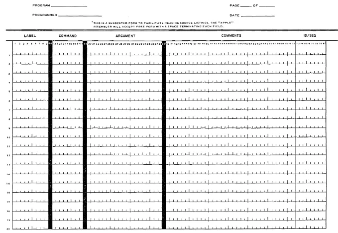
APPLE Assembler Coding Form . • . . . • . . • • . . . • . • . . . • . . . • • .
0..
2-2Device Assignment Table (OAT) .•..•.•. 0 • • • • • • 0 . 0 0 • • • • • • • • • • 0 • • • • 0 3-2
LIST OF TABLES
TITLE PAGE
Registers ••.•••.•.• 0 0 . 0 • • • • • • • • 0 • • • • • • 0 • • • • • 0 • • • • • • 0 . . . . • • • • • • • • 2-36
GENERAL
APPLE MANUAL
CUSTOM INPUT/ OUTPUT
FOREWORD
The APPLE Programming Manual is one of five standard manuals for STARAN S. As a composite group, the manuals provide the information necessary for programming, operating, and maintaining the standard STARAN S. The titles and publication numbers of the STARAN S manuals are as follows:
STARAN S Reference Manual
STARAN S APPLE Programming Manual STARAN S Operator's Guide
STARAN S Systems Programmer's Reference Manual STARAN S Maintenance Manual
Publication GER -15636 GER -15637 GER -15638 GER -15639 GER -15640
The APPLE Programming Manual is intended as a reference manual to guide the programmer in the use of the assembly language. The manual is written for the experienced programmer who has familiarized himself with the STARAN S Reference Manual, GER -15636.
Since the I/O cabinets are not standard units, but are customized for each particular installation, this manual include s no de scription of I/O mnemonic s included in the APPLE language of a given installation.
SASIC
(
FOUR-CASINET) STARAN SYSTEM
KEYBOARD PRINTER
STARAN S COMPUTER SYSTEM
OPTIONAL ASSOCIATIVE ARRAY CABINETS
GENERAL
'~TM.
CHAPTER 1
INTRODUCTION
The Goodyear Aerospace Corporation (GAC) Associative Processor,
STARAN S':(, is a new digital computer system differing significantly
from conventional digital computers.
The Associative Processor (AP) is a general-purpose computer
capable of performing search, arithmetic, logic, and store operations
simultaneously on many independent sets of data. This capability,
which is a feature unique to STARAN S, results in certain major
differences between programming techniques for STARAN S and those
for conventional machines.
As an example, consider the familiar "loop" programming concept.
A loop is defined as a set of commands repeatedly and consecutively
executed on different sets of data. Conventional programming of a
loop involves the following steps:
1. Initialize
+~
~l
2.
Process3. A(lvance
+
List Pointer+ .
4. ExamIne Exit Criterion
J
s.
D~cide
6.
Act on .. D ecislon . ~!
To process a new set of data conventionally requires execution of the
complete loop, including steps 3, 4, 5, and
6,
as coding and execution time overhead.In an AP, execution of the equivaleht of a loop on associative items
requires initialization and a single pass through the process step.
There is no need to advance a list pointer to reference the next set of
data to be processed, to determine when to exit from the loop, or to
repeatedly execute the process step. The loop is one of many examples
of program simplification and improved execution time possible with
an AP.
Goodyear Aerospace Corporation, Akron, Ohio 44315
APPLE
ONE-TO-ONE
ONE-TO-MANY
In Line
Subroutine Call Sequence
ASSEMBLER DIRECTIVES
Development of a new digital machine organization involves the design
of a programming language suitable for the computer.
APPLE is the acronym for the ~ssociative ..!:rocessor ..!:rogramming
Languag~. APPLE is a machine-oriented symbolic language designed
to expedite programming for the STARAN S system.
APPLE mnemonics produce four basic types of assembler generated
output:
1) One-to-One Translation
2) One-to-Many Translation
3) Assembler Directives
4) Comment Statements
Most assembler level languages for conventional computers generate one
machine language instruction per mnemonic. Many of the basic APPLE
mnemonics fall into this category.
Several APPLE mnemonics are in the one-to-many category. Many
basic AP programming functions require more than one machine
language instruction per mnemonic. Some of these mnemonics pronuce
in-line machine instructions; others generate a subroutine call to a
sequence of machine instructions.
The one-to-many mnemonics producing in-line machine instructions are
equivalent to macro instructions of higher level assembly languages.
A library of subroutines is provided by APPLE and resides in Page 0
memory. The one-to-many mnemonics produce in-line subroutine call
sequences similar to the linkages provided in FORTRAN to the SIN or TAN
functions of a FORTRAN library.
Assembler directive statements provide functions that assist the
programmer in controlling the assignment of storage addresses, defining
data and storage fields, and controlling the APPLE system itself. With
a few exceptions, assembler directive statements do not generate
APPLE FEATURES
APPLE is essentially a symbolic assembly language. All AP memories and registers may be referenced symbolically. Constants can be expressed as decimal, octal, or hexadecimal numbers in source statements. Addresses can be expressed absolutely or symbolically.
A listing of the source program statements, the resulting machine language code, and a symbol table may be produced by APPLE for each program. When a source program is assembled, an extensive syntactical check is provided by APPLE. Detected errors are printed on the program listing in error codes (Appendix B) at the left-hand margin of the particular statement in error. A maximum of two error codes can be printed for each statement.
QUICK INDEX
APPLE INSTRUCTION GROUPS
ASSEMBLER DIRECTIVES
I
BRANCH INSTRUCTIONS _ _ _ _ _ _ _ _ _ _ _ _ _ _
REGISTER INSTRUCTIONS _ _ _ _ _ _ _ _ _ _ _ _
...JI
ASSOCIATIVE INSTRUCTIONS
---...11
Loads ___________________________________111
Stores __________________________________
111
Searches ______________________________
~III
Moves ________________________________
~III
SOURCE STATEMENTS
LABEL FIELD
COMMAND FIELD
ARGUMENT FIELD
CHAPTER 2
APPLE LANGUAGE STRUCTURE
The source statement is the basic component of an APPLE program.
Source statements consist of the following four entries: Label, Command
Argument, and Comment. APPLE accepts source statements in free format.
Blanks act as field delimiters. The suggested coding form for source
statements is shown in figure 2 -1. The columns on the coding form
correspond to those of a standard 80-column Hollerith coded card. One
line of coding on the form corresponds to one source card.
Columns 1 through 72, inclusive, constitute the active line. Columns
73 through 80 are ignored by APPLE except for listing purposes. The
source statement may be continued past 72 columns by inserting
a semicolon (;), which, when scanned, terminates the present active
line. APPLE then searches the next active line to complete the
source statement.
The Label Field is usually an optional symbol created by the
pro-grammer to identify the statement line. The symbol may consist of
nine characters or less, with the first character in column one. If
the first column is blank, the Label entry is assumed omitted. The
symbol in the Label Field can contain alphabetics (A- Z) or numerics
(0-9); however, at least one of the characters must be an alphabetic.
The Label Field entry may have the same configuration as predefined
mnemonics without conflict, since APPLE distinguishes through
context which usage is intended. Only one entry is permitted in the
Label Field.
The Command Field is a requirement. It may consist of several
symbols separated by commas (,). The first symbol is the
predefined mnemonic (Appendix A) for a particular command.
Command modifiers may follow the command, depending upon the
individual command. No embedded blanks are allowed in the Command
Field.
Entries in the Argument Field properly specify the instruction. In
general, the purpose of this field is to identify the source and
destination locations to the command. Other entries, such as Control
Digits, are also included in this field. The entries are separated by
commas and no embedded blanks are allowed. APPLE assumes no
Argument Field entries if 16 contiguous blanks follow the Command
L-1751(5-72)
* APPLE ASSEMBLER CODING FORM
I 2 3 4 5 15 7 8 II 10
"
12 13 14PROGRAM _ _ _ _ _ _ _ _ _ PAGE _ _ _ OF _ _ _ _
PROGRAMMER _ _ _ _ _ _ _ _ _ _ _ DA TE _ _ _ _ _ _ _ _ _
LABEL COMMAND
1 2 3 4 5 6 7 8 9 • 1\1213141516171
I I I I I 1 1. i
I I I I I I I I I
I I
J.. -.I I I I I I I I I I I
J...l I 1 I I I I I I I I
..l ..l I I 1 I 1 t i l I
I I I 1 I I I
-'- 1 I 1 I I I I I I
L 1 I I I
J I I I I I
-.I J ..l I I I I
I I 1.1 I I
I I I .1 I I
I I I
'THIS IS A SUGGESTED FORM TO FACILITATE READING SOURCE LISTINGS, THE "APPLE"
ASSEMBLER WILL ACCEPT FREE FORM WITH A SPACE TERMINATING EACH FIELD.
ARGUMENT COMMENTS
• 202122232425262728293031323334353637.38 • 404142434445464748495051525354555657585960 6162 6364656667 686~ 7071 72
J - ' - I I -.I. ~I I I I I I I I I I I I 1 I J -'-.1 I I I I I I I
I I I 1 I I I I I I J j i I I I I I I I I I I I I I I I I I I I I I I I I 1. i l l
I 1 I 1 I J i i i 1 -.I -'- J -'- I 1 I 1 I I I I 1 I I 1 I I 1 I I I I
I 1 I I I I I I 1 1 I I I 1 I I 1 I I 1 1 I I t I 1 I I I I -'- I
1-,-I I I I I I I I I I I I I I I I I 1 I I 1.1 I I 1.1 I . I I I 1 I
.
I I I ~I 1 II I I I 1 I I I I I I I I I I I I I I I I I I I I I I I I I 1 I I I
I 1 I I I I I I I I I I I I I , I I 1 I I I I I I 1 I I 1 I i
I
II I 1 I I I I I I I I I I I I I I I I I 1 I I I I I I 1 I I I I I
I I I I 1 I I I I I I I I I I I I I I I I I I 1 1 I I I I I I I I I 1. I I I 1 I I
I I I I I I I I I I I I I I I I I I I I I I I I I I I I I
I I I I I I I I I I I I I I I I I I I I I I .I I I .11
,1
i I I I I I I I f I 1 I I 1 I I I I I I 1 I I I I I I I I I I I I I I 1 I I I I I I I I -.It t
I 1 I I I I I 1 I I I I I I I I I I I I j I I I I I I I I i I 11 I I I I I I I I
I I 1 1 .1 i I I I I I I I I I I I I I I I I I I I I I I I I I
ID/SEQ
7374757677787~8C
I I 1
1 I I I 1
1 I I I 1 1
1.1.~-'-L-'-.1
I I I I
I I I 1 1
I I I I I
I 1 I .1 I I t
I I I I
I I I I
1 f I
I I I
I I I I I I I
[image:15.796.74.753.79.547.2]ARGUMENT FIELD ( cont)
COMMENT FIELD
REQUIRED ENTRIES
SUMMARY
Field. Symbols appearing in the Argument Field must be defined to
the program, either by being predefined by APPLE or by appearing
in the Label Field of a source statement.
Comments are descriptive items of information that may be included
on the program listing. Comment entries consist of any information
the programmer wishes to record. All valid characters, including
blanks, can be used. The Comment Field begins one blank after the
Argument Field, or if no Argument Field exists, comments begin
after 16 contiguous blanks follow the Command Field. An asterisk
(~:c) in column one indicates the entire source statement is a comment.
Required entries for the various mnemonics are underlined in the
~"ormat description of each instruction discussion {i. e., B ~(r)±k, cd).
1) APPLE interprets the fields from left to right: Label,
Command, Argument, Comment.
2) A blank column terminates any field except the Comment Field,
which is terminated at column 80.
3) One or more blanks at the beginning of a line indicates there is
no Label Field entry.
4) The Label Field entry, when present, must begin in column 1.
5) The Command Field begins with the first nonblank column
following the Label Field or in the first nonblank column
follow-ing column 1, if the Label Field is omitted.
6) The Argument Field begins with the first nonblank column
following the Command Field. An Argument Field is designated
as being blank in either of two ways:
a. Sixteen or more blank columns follow the Command Field.
b. The end of the active line (column 72) is encountered and
continuation is not indicated.
7) The Comment Field begins in the first nonblank column following
the Argument Field, or when the Argument Field is omitted,
at least 16 blank columns following the Command Field.
LANGUAGE ELEMENTS
CHARACTER SET
SYMBOLS
APPLE language statements are written using the following
alphabetics, numerics, operators, and delimiters:
Alphabetics A through Z
Numerics 0 through 9
Operators $+-~:::=
Delimiters () BLANK I
Each character is represented by an 8-bit byte. Only 47 characters
of the set of 256 code combinations defined as the Extended Binary
Coded Decimal Interchange Code (EBCDIC) are included in APPLE's
character set. Most of the terms used in APPLE source statements
are expres sed in the character set shown above; however, language
features, such as comments, permit the use of any of the 256 EBCDIC
codes.
Symbols are formed from combinations of characters. Symbols
provide programmers with a convenient means of identifying program
elements so that they can be referred to by other elements. Symbols
must conform to the following rules:
1) Symbols consist of 1 to 9 alphanumeric characters.
2) At least one character in a symbol must be alphabetic.
3) No special characters or embedded blanks can appear in a symbol.
4) A symbol may be defined only once. If duplicate symbols occur
they will be flagged as errors.
Symbols provide the most commonly used means of addressing source
statements, constants, and storage locations. Symbols are normally
defined in the Label Field of a source statement. After a symbol has
CONSTANTS
Octal Constants
Decimal Constants
Hexadecimal Constants
A constant is a self-defining language element whose value is explicit.
Self-defining terms are useful in constants requiring a value rather
than the symbolic address of the location where that value is stored.
Three constant notations are used in APPLE instructions: octal,
decimal, and hexadecimal.
An octal constant consists of a signed octal number enclosed by single
quotation marks and preceded by the letter O.
The constant is right -justified in its field. For example,
Constant Binary Value Hexadecimal Value
0' 1234' 001 010 all 100 0010 1001 1100
The octal digits and their binary equivalents are as follows:
a -
000 1 - 001 2 - 010 3 - all4 - 100 5 - 101
6 -
1107 - III
(29C)
A decimal constant consists of an integer (no decimal point) that may
be signed. For example, 100 or -5423.
A hexadecimal constant consists of a signed hexadecimal number
ene!osed by single quotation marks and preceded by the letter X.
F or example,
X' 9C01F' X' COFFEE' X' FFFF'
The assembler generates four binary bits of storage for each
hexa-decimal digit. The hexadecimal digits and their binary equivalents
are as follows:
a - 0000 1 - 0001
2 - 00 1
a
3 - 0011 4 - 0100 5 - 0101 6 - 0110 7 - 0111
8 - 1000 9 - 100 1 A-lOla B - 1011 C - 1100 D - 1101 E- 1110
F_ 1111
EXPRESSIONS
Examples
LOCATION COUNTERS
Load Location Counter
Execution Location Counter
Argument Field entries consist of either single-term expressions or double-term expressions. Single-term expressions are symbols, constants, or Location Counter references ($). Double-term expressions are two single terms connected with an arithmetic operator. The valid arithmetic operators are a plus sign (+) for addition and a minus sign (-) for subtraction. The first single-term expression of a double -term expression may be a symbol or constant, and the second single-term expression must be a constant.
Valid TAG+5 LABEL-23 5+32
Invalid TAG-LABEL 5+TAG TAG+5+23
APPLE maintains two internal Location Counters: a Load Location Counter and an Execution Location Counter. The Load Location Counter keeps track of the addresses associat~d with the instructions when the program is loaded. The Execution Counter keeps track of the addresses associated with the instructions when they are executed.
The Load Location Counter keeps track of the addresses associated with the instructions when they are loaded.
As each instruction or data area is assembled, the Load Location Counter is incremented by the length of the assembled item. There-fore, the Load Location Counter is the address of the next available
storage location in Control Memory after the instruction is assembled. This address is the location where the instruction will reside after being loaded.
As each instruction or data area is assembled, the Execution Location Counter is incremented by the length of the assembled item. The
ADDRESSING
Control Memory Address
Associative Memory or Common Register Field Expression
The Control Memory Address is a symbolic or absolute address in
bulk core, page memory, or High Speed Data Buffer. A Control
Memory Address expression is comprised of four terms in the form
~ (r)±k,cd. Note that required terms are underlined.
a - This entry is the only one required. This term may be
a symbol or a constant.
k - This entry must be a constant. At assembly time :l:k is
added to the value of lal to form the address.
r - This entry must be one of the following registers:
RO through R7, DP.
At execution time the contents of this specified register is
added to the value a±k. It is this result that defines the
Control Memory Address. The contents of the register can
be considered to be the base address, and the double-term
expression a±k can be considered to be the displacement.
cd _ This entry is the Control Digit. A Control Digit indicates
that after the specified instruction is completed a step is
desired. This step may increment or decrement the data
pointer (DP) register by one and/or decrement the- block
length (BL) register by one. The Control Digit may be
specified by an a:l:k type of expression, where I a' - and I k'
are defined as above.
cd Values
2
3
4 5
Action
Decrement BL
Increment DP
Decrement BL and Increment DP
Decrement DP
Decrement BL and DP
The Control Digit is a valid entry only when the base
register option has been selected, and the register forming
the base register is the DP register.
A field expression defines the most significant bit position and the
number of contiguous bit positions (field length) occupied by a field.
There are two ways of constructing a field expression:
Associative Memory or Common Register Field Expression ( cont)
• 1
• 2
• Example 1
• Example 2
b±:i
where b must be a symbol, and i is an optional constant modifier.
b should have been previously defined in a DF instruction. b
represents the most significant bit position and the number of
contiguous bits occupied by a field in either the Common register
or Associative Memory. The optional constant modifier, i, modifies
only the most significant bit position.
(b, i)±j
where b may be a constant or a symbol and represents the most
significant bit position of a field. If b was defined as a field via a
previous DF instruction, the most significant bit position is the value
used. i must be a constant and represents the number of contiguous
bits occupied by the field. j is an optional constant modifying only the
most significant bit position of the field.
AJAX DF 10,3
SC AJAX-3,(100,3)
The field AJAX begins in bit column 10 and spans 3 bit columns
(bit columns la, II, 12).
The expression AJAX - 3 has modified the most significant bit position
to a value of 7 and spans 3 bit columns (bit columns 7, 8, 9).
The expression (100,3) defines a field beginning with bit column 100
and spans 3 bit columns (bit columns 100, 101, 102).
FIELD1 DF
a,s
ASSEMBLER DIRECTIVES
Assembler directive statements provide auxiliary functions to APPLE and assist the programmer in checking, documenting, and organizing a program.
The assembler directives are:
Mnemonic
START END ORG
EQU
DF DS TOF EVEN DC GEN NOP A or E
Instruction
Start APPLE End APPLE
Initialize Location Counter Equate
Define a Field Define Storage Top of Form
Make Location Counter Even Define Constant
Generate Machine Instructions No Operation
Character String Generator
I
START
Format
• Label
• Command
• Argument
END
Format
• Label
• Command
• Argument
Start APPLE
This instruction performs initializing functions for APPLE, and generates pertinent header information for all object programs. This instruction is required and should be the first source statement in all APPLE programs.
Label Command Argument Comment
symbol START
Any valid symbol or blank.
START
No entry required.
End APPLE
This instruction will process and assemble all previous source program statements. The END instruction is required and must be the last source statement of every assembly.
Label Comma.nd Argument Comment
symbol END a:!:k
Any valid symbol or blank.
END
ORG
Format
• Label
• Command
• Argument
• • a±k
Example
• Note
Initialize Location Counter
This instruction commands the assembler to assemble succeeding instructions
beginning at the address specified in the Argument Field. The Load Location
Counter and Execution Location Counter are loaded with the value of a±k.
Label Command Argument Comment
symbol ORG a±k
Any valid symbol or blank.
ORG
One entry is required.
'a' may be either a symbol or a constant whose value may be optionally modified by plus or ITlinus the constant k. Moreover' a'
may be one of the following special predefined symbols provided
for ease of programming:
a
PAGED PAGEl
PAGE2
HSDB
DMA
BULKC
ORG
Definition
Page 0 Memory Starting Address
Page MeITlory Starting Address
Page 2 MeITlory Starting Address
High-Speed Data Buffer Memory Starting Address
Direct Memory Access Memory Starting Address
Bulk Core Storage Memory Starting Address
BULKC+16
In this example the first instruction following the ORG statement will be
assigned the Bulk core address X' 8020' (BULKC assigns the address
X' 8010' in the APPLE assembler).
EQU
Format
• Label
• Command
• • a±k
DF
Format
• Label
• Command
• Argument
Equate
This instruction permits the programmer to assign a value to a symbol.
Whenever the symbol appears in a succeeding instruction, the equated
value will be used to form the machine language code.
Label Command Argument Comment
symbol
EQU
~±kAny valid symbol. This entry is required.
EQU
'a' may be either a symbol or a constant whose value may be optionally
modified by plus or minus the constant k. la l ITIay also be one of the special
predefined APPLE sYITIbols such as register abbreviations (Table 2 -1) PAGEO,
PAGE 1, PAGE2, HSDB, DMA, B ULKC , X, Y I and M. Huwever , if a special
syITIbol is us ed it cannot be ITIodified by k.
Define a Field
This instruction permits the programmer to as sign a field definition
value to a symbol for later use. Whenever the symbol appears in
instructions, the defined field value will be used to form the machine
language code.
Label Command Argument Comment
symbol DF
Any valid symbol. This entry is required.
DF
Two entries are required.
DS
Format
• Label
• Command
• • a±k
• Argument
TOF
Format
• Label
• Command
• Argument
• Comment
Define Storage
This assembler directive will allocate the next specified number of
32 bit words as a contiguous block of control memory.
Label Command Argument Comment
symbol ~a±k
Any valid symbol or blank.
DS
'a' may be either a symbol or a constant whose value may be optionally
modified by plus or minus the constant k. The value of the term a±k
specifies the number of contiguous words to be reserved. If this entry
is omitted, a default value of one is assumed.
Blank
Top of Form
This assembler directive will issue a form feed to the assembly
listing device. TOF may be placed anywhere in the program and
has no effect on the object code produced.
Label Command Argument Comment
TOF
Must be blank.
TOF
None required.
The comment will be printed at the top of the page after the form feed.
EVEN
Format
• Label
• Command
• Argument
DC
Format
• Label
• Command
Make Location Counter Even
If the Execution Location Counter is odd when this instruction is
encountered, an NOP will be produced in the object code; otherwise, no
object code will be produced. Therefore, after this instruction has been
processed the Execution Location Counter will be even. (Ref. SPSW instruction.)
Label Command Argument Comment
symbol EVEN
Any valid symbol or blank.
EVEN
N one required.
Define Constant
This instruction will generate a specified value for a specified
number of 32 bit control memory words.
Label Command Argument Comment
symbol
Any valid symbol or blank.
DC
al may be either a symbol or a constant whose value may be optionally
modified by plus or minus the constant kl. The value of the term al±k l
GEN
Format
• Label
• Command
• Argument
Note
NOP
Format
• Label
• Command
• Argument
Generate Machine Instructions
This instruction permits the programmer to generate machine codes for
instructions not covered by APPLE. (See STARAN S Reference Manual for detailed machine language coding.) This instruction is also useful
when generating words of data rather than instructions.
Label Command Argument Comment
symbol GEN, k), ••• ,kn
Any valid symbol or blank.
GEN
One or more constants that define the length of the consecutive data fields
ai±ji respectively. The sum of all the kl s must be less than or equal to 32.
a
i may be either a symbol or a constant whose value may be optionally modified by plus or minus the constant ji. These term{s) represent the
value{ s) to be inserted into each of the corresponding data field{ s).
There must be a one-to-one correspondence between the k i and ai±ji terms.
If the sum of the lengths of the data fields is less than 32, the information
will be right-justified in the word.
No Operation
This instruction performs no operation when it is executed.
Label Command Argument Comment
symbol NOP
Any valid symbol or blank.
NOP
No entry required.
2-15
A or E
Format
or
• Label
• Command
• • A
• • E
• • x
• • c 1 cZ· - - ci -1 ci
• Argument
Note
Character String Generator
These two assembler directives enable the programmer to generate
messages for output.
Label Command Argument Comment
symbol Axc 1 c Z· .• c i-I c· 1 _ X
Label Command Argument Comment
symbol Exc1cZ···ci_l c· 1 x
Any valid symbol or blank.
A character string entry is required.
I AI represents an assembler directive commanding the as sembler to
generate the seven bit ASCII code equivalent to the succeeding character
string.
E represents an assembler directive commanding the assembler to
generate the eight bit EBCDIC code equivalent to the succeeding
character string.
x must be any non-alphanumeric character and serves as the "begin" and
"end" marker of the character string cl cZ- _ • ci_l ci' x cannot be
a I ; I .
The ci may be any allowable ASCII or EBCDIC character (except the I j I)
depending on whether A or E is used respectively. One or more full
thirty-two bit words are generated with the ASCII or EBCDIC code of the ci
packed on byte boundaries at four characters per word. If there are not
enough character s to generate a full word, the remaining bytes will be
padded with blank (or space) characters.
No entry is required.
There is no provision for continuation of a character string onto
several source cards.
BRANCH INSTR UCTIONS
Branch instructions alter the execution sequence of a program if certain
conditions exist.
The branch instructions are:
Mnemonic Instruction
B Unconditional Branch
BZ Branch if Zero
BNZ Branch if Not Zero
BBS Branch if Bit Set
BBZ Branch if Bit Zero
BRS Branch if Re sponse
BNR Branch if No Re sponse
BOV Branch if Overflow
BNOV Branch if No Overflow
BAL Branch and Link
RPT Repeat
LOOP Loop
B
Fortnat
•
Label•
Cotntnand•
Argutnent • • a• • k
• • r
• • cd
Unconditional Branch
This instruction will transfer control frotn the current progratn address to the address specified in the Argutnent Field.
Label Cotntnand Argutnent Cotnment
sytnbol B ~(r)±k, cd
Any valid sytnbol or blank
B
The Control Metnory Address is a symbolic or absolute address in Bulk Core, Page Memory, or High-Speed Data Buffer. The Control Memory Address may be represented by four terms in the form a(r)±k, cd.
This entry is required only if the optional term (r) is omitted. This term may be either a symbol or a constant.
This optional term must be a constant and modifie s 'a' .
This entry may be one of the following nine registers: R 0 through R 7, DP . The contents of this specified register is added to the value a±k at execution time. It is this result that defines the Control Memory Address. The
contents of the register can be considered the base address, and the a±k expre ssion can be considered the displacement.
This entry is the Control Digit. A Control Digit indicates that after the
specified instruction is completed a step is desired. This step may increment or decrement the data pointer (DP) register by one and/or decrement the block length (BL) register by one. The Control Digit may be specified by an a±k type of expression where 'a' and k are as defined above.
cd Values
1 2
3
4 5
Action Decrement BL Increment DP
Decrement BL and increment DP Decrement DP
Decrement BL and DP
BZ
Format
•
Label•
Command• Argument
• • a
• • k
Branch if Zero
This instruction will transfer control from the current program addre s s
to the address specified in the argument field, if the command field register,
r I' is zero.
Label Command Argument Comment
symbol BZ, r
1
Any valid symbol or blank.
BZ
Register
FPl FPZ FP3 FLl FLZ FPE BL DP
Definition
Field Pointer 1 (8 bits) Field Pointer Z (8 bits) Field Pointer 3 (8 bits)
Field Length Counter 1 (8 bits) Field Length Counter Z (8 bits) Field Pointer E (8 bits)
Block Length Counter (16 bits) Data Pointer Register (16 bits)
The Control Memory Address is a symbolic or absolute address in Bulk
Core, Page Memory, or High-Speed Data Buffer. The Control Memory
Address may be represented by four terms in the form a(rZ)±k, cd.
This entry is required only if the optional term (rz) is omitted. This
term may be either a symbol or a constant.
This optional term must be a constant and modifie s 'a'.
This entry must be one of the following nine registers: RO through R 7,
DP. The contents of the specified register is added to the value a±k
at execution time. The result defines the Control Memory Address.
The contents of the register can be cO"G.sidered the base address, and the
a±k expression can be considered the displacement.
BZ
• • cd This entry is the Control Digit. A Control Digit indicate s that after the specified instruction is completed a step is desired. This step may increment or decrement the data pointer (DP) register by one and/or decrement the block length (BL) register by one. The Control Digit may be specified by an a±k type of expression, where tat and k are as defined above.
cd Values 1 2 3 4 5
Action Decrement BL Increment DP
Decrement Bl and increment DP Decrement DP
Decrement BL and DP
The Control Digit is a valid entry only when the base register option has been selected, and the register forming the base register is the DP register.
BNZ
Format
• Label
•
Command• Argument
• • a
• •
k• •
• • cd
Branch if Not Zero
This instruction will transfer control from the current program address
to the addre s s specified in the argument field, if the command field register,
r l' is not zero.
Label Command Argument Comment
symbol ~(r2 )±k, cd
Any valid symbol or blank.
BNZ
Register
FPl FP2 FP3 FLl FL2 FPE BL DP
Definition
Field Pointer 1 (8 bits) Field Pointer 2 (8 bits) Field Pointer 3 (8 bits)
Field Length Counter 1 (8 bits) Field Length Counter 2 (8 bits) Field Pointer E (8 bits)
Block Length Counter (16 bits) Data Pointer Register (16 bits)
The Control Memory Address is a symbolic or absolute address in Bulk
Core, Page Memory, or High-Speed Data Buffer. The Control Memory
Address may be represented by four terms in the form a(r2)±k, cd.
This entry is required only if the optional term (r2) is omitted. This term
may be either a symbol or a constant.
This optional term must be a constant and modifie s 'a '.
This entry may be one of the following nine registers: R
a
through R 7, DP. The contents of the specified register is added to the value a±k at executiontime. It is this result that defines the Control Memory Address. The contents
of the register can be considered the base address, and the a±k expression
can be considered the displacement.
This entry is the Control Digit. A Control Digit indicate s that after the
specified instruction is completed a step is desired. This step may
increment or decrement the data pointer (DP) register by one and/or
decrement the block length (BL) register by one. The Control Digit
may be specified by an a±k type of expression, where 'a' and k are
defined as above.
2-21
BNZ
• • cd (cant)
cd Values
I
2
3
4 5
Action Decrement BL Increment DP
Decrement BL and increment DP Decrement DP
Decrement BL and DP
BBS
Format
• Label
• Command
• Argument
• • a
• • k
• • r
• • cd
Branch if Bit Set
The execution of the branch in this instruction is contingent on the status of a selected bit in the Common register. Prior to execution of this instruction, an instruction must be executed to load the FP 1 register with the address of the bit in the Common register to be tested for the contingency. If the selected Common register bit is one, this instruc-tion will transfer control from the current program address to the address specified in the Argument Field.
Label Command Argument Comment
symbol BBS a(r)±k, cd
"
-Any valid symbol or blank.
BBS
The Control Memory Address is a symbolic or absolute address in Bulk Core, Page Memory, or High-Speed Data Buffer. The Control Memory Address may be represented by four terms in the form a(r)±k, cd.
This entry is only required if the optional term (r) is omitted. This term may be either a symbol or a constant.
This optional term must be a constant and modifies' a' •
This entry may be one of the following nine registers: RO through R 7, DP. The contents of the specified register is added to the value a±k execution time. The result defines the Control Memory Address. The contents of the register can be considered the base address, and the a±k expression can be considered the displacement.
This entry is the Control Digit. A Control Digit indicates that after the specified irstruction is completed a step is desired. This step may increment or decrement the data pointer (DP) register by one and/or decrement the block length (BL) register by one. The Control Digit may be specified by an a±k type of expression, where' a' and k are
defined as above.
cd Values
1
2
3
4 5
Action Decrement BL Increment DP
Decrement BL and increment DP Decrement DP
Decrement BL and DP
The Control Digit is a valid entry only when the base register option has been selected, and the register forming the base register is the DP register.
BBS
Example
• Common Register Contents
TAG
CaNT
o
LI BBS
FP1,24 TAG
DECR FP1 BBS CaNT WAIT
LRR C,FP2
CHECK BIT 24
BRANCH IF BIT IS ONE
CHECK BIT 23
BRANCH IF BIT IS ONE
23 24 31
The first branch (BBS TAG) will take place, since FPl is loaded with 24 and bit 24 in the Common register is one.
BBZ
Format
• Label
• Command
• Argument
• • a
• • k
• • r
• • cd
Branch if Bit Zero
The executipn of the branch in this instruction is contingent on the status of a selected bit in the Common register. Prior to execution of this instruction, an instruction must be executed to load the FP 1 register with the address of the bit in the Common register to be tested for the contingency. If the selected Common register bit is zero, this instruction will transfer control from the current program address to the address specified in the argument field.
Label Command Argument Comment
symbol BBZ ~(r}±k, cd
Any valid symbol or blank.
BBZ
The Control Memory Address is a symbolic or absolute address in Bulk Core, Page Memory, or High Speed Data Buffer. The Control Memory Address may be represented by four terms in the form a(r)±k, cd.
This entry is required only if the optional term {r} is omitted. This term may be either a symbol or a constant.
This optional term must be a constant and modifies' a' •
This entry may be one of the following nine registers: RO through R7,
DP. The contents of the specified register is added to the value a±k at execution time. The result defines the Control Memory Address. The contents of the register can be considered the base addre s s, and the a±k expression can be considered the displacement.
This entry is the Control Digit. A Control Digit indicates that after the specified instruction is completed a step is desired. This step may increment or decrement the data pointer {DP} register by one and/or decrement the block length (BL) register by one. The Control Digit may be specified by an a±k type of expression, where' a' and k are defined as above.
cd Values 1 2
3
4 5
Action Decrement BL Increment DP
Decrement BL and increment DP Decrement DP
Decrement BL and DP
The Control Digit is a valid entry only when the base register option has been selected, and the register forming the base register is the DP
BBZ
Example
• Common Register Contents
TAG
CaNT LI BBZ
INCR BBZ WAIT
FPl, 10
TAG
FPl CaNT
DECR FP2
CHECK BIT 10
BRANCH IF ZERO
CHECK BIT 11
BRANCH IF BIT IS ZERO
BRS
Format
• Label
• Command
• Argument
• • a
• • k
• • r
• • cd
Branch if Response
This instruction will check the Y response store register. If any Y response store register bit position is set to one in any enabled array, the branch will be executed.
Label Comma.nd Argument Comment
symbol BRS ~{r}±k, cd
Any valid symbol or blank
BRS
The Control Memory Address is a symbolic or absolute address in Bulk Core, Page Memory, or High-Speed Data Buffer. The Control Memory Address may be represented by four terms in the form a{r}±k, cd.
This entry is required only if the optional term {r} is omitted. This term may be either a symbol or a constant.
This optional term must be a constant and modifies' a' •
This entry may be one of the following nine registers: RO through R 7, DP. The contents of the specified register is added to the value a±k at execution time. The result defines the Control Memory Address. The contents of the register can be considered the base address, and the a±k expression can be considered the displacement.
This entry is the Control Digit. A Control Digit indicates that after the specified instruction is completed a step is desired. This step may increment or decrement the data pointer {DP} register by one and/or decrement the block length (BL) register by one. The Control Digit may be specified by an a±k type of expression, where' a' and k are as
defined above.
cd Values
1
2
3 4
5
Action Decrement BL Increment DP
Decrement BL and increment DP Decrement DP
Decrement BL and DP
The Control Digit is a valid entry only when the base register option has been selected, and the register forming the base register is the DP register.
BNR
Format
• Label
• Command
• Argument
• • a
• • k
• • r
• • cd
Branch if No Response
This instruction will check the Y response store register. If all
Y response store register bit positions are equal to zero in all
enabled arrays, the branch will be executed.
Label Command Argument Comment
symbol BNR ~(r}±k, cd
Any valid symbol or blank.
BNR
The Control Memory Address is a symbolic or absolute address in
I
Bulk Core, Page Memory, or High Speed Data Buffer. The Control Memory
Address may be represented by four terms in the form a(r}±k, cd.
This entry is required only if the optional term (r) is omitted. This
term may be either a symbol or a constant.
This optional term must be a constant and modifies I a' •
This entry may be one of the following nine registers: RO through R 7,
DP. The contents of this specified register is added to the value a±k at
execution time. The result defines the Control Memory Address. The
contents of the register can be considered the base address, and the
a±k expression can be considered the displacement.
This entry is the Control Digit. A Control Digit indicates that after the
specified instruction is completed a step is desired. This step may
increment or decrement th,e data pointer (DP) register by one and/or
decrement the block length (BL) register by one. The Control Digit may
be specified by an a±k type of expression, where' a' and k are defined as
BOV
Format
• Label
• Command
• Argument
• • a
• • k
• • r
• • cd
Branch if Overflow
This instruction allows the programmer to test for an overflow or
underflow condition after an arithmetic operation. This instruction will
perform X exclusive OR Y ANDed with M and store the re sult in Y. Then
if any Y response store bit in any enabled array equals one an overflow condition exists for that word. If such is the case, this instruction will
branch to the address specified in the Argument Field. The X response
store will equal one for the corresponding word of associative memory
if an underflow occurred; otherwise an overflow occurred.
Label Command Argument Comment
symbol BOV 2:,(r)±k, cd
Any valid symbol or blank.
BOV
The Control Memory Address is a symbolic or absolute address in
Bulk Core, Page Memory, or High Speed Data Buffer. The Control Memory
Address may be represented by four terms in the form a(r}±k, cd.
This entry is required only if the optional term (r) is omitted. This
term may be either a symbol or a constant.
This optional term must be a constant and modifies t at.
This entry may be one of the following nine registers: RO through R7,
DP. The contents of this specified register is added to the value
a±k at execution time. The result defines the Control Memory Address.
The contents of the register can be considered the base address, and
the a±k expression can be considered the displacement.
This entry is the Control Digit. A Control Digit indicates that after
the specified instruction is completed a step is desired. This step
may increment or decrement the data pointer (DP) register by one
and/or decrement the block length (BL) register by one. The Control
Digit may be specified by an a±k type of expression, where t at and k are
defined as above.
cd Values
1
2
3 4
5
Action
Decrement BL Increment fDP
Decrement BL and increment DP Decrement DP
Decrement BL and DP
The Control Digit is a valid entry only when the base register option has
been selected, and the register forming the base register is the DP register.
BNOV
Format
•
Label•
Command• Argument
• • a
• • k
• • r
• • cd
Branch if No Overflow
This instruction allows the programmer to test for the absence of an
overflow or underflow condition following an arithmetic instruction.
This instruction will perform X exclusive OR Y ANDed with M and store
the result in Y. If all Y response store bits of all enabled arrays equal
zero, i. e., no overflow condition exists, this instruction will branch to
the addre ss specified in the Argument Field. If the branch doe s not take
place, the X response store will equal one for the corresponding word of
associative memory if an underflow occurred; otherwise, an overflow
occurred.
Label Command Argument Comment
symbol BNOV ~(r)±k, cd
Any valid symbol or blank.
BNOV
The Control Memory Address is a symbolic or absolute address in Bulk
Core, Page Memory, or High-Speed Data Buffer. The Control Memory
Address may be represented by four terms in the form a(r)±k, cd.
This entry is required only if the optional term (r) is omitted. This
term may be either a symbol or a constant.
This optional term must be a constant and modifies la l .
This entry may be one of the following nine registers: R 0 through R 7, DP.
The contents of this specified register is added to the value a±k at execution
time. The result defines the Control Memory Address. The contents of the
register can be considered the base address, and the a±k expression can be
considered the displacement.
This entry is the Control Digit. A Control Digit indicates that after the
specified \instruction is completed a step is desired. This step may increment
or decrement the data pointer (DP) register by one and/or decrement the
block length (BL) register by one. The Control Digit may be specified by
an a±k type of expression, where 'al and k are defined as above.
BAL
ForMat
• Label
• Command
• Argument
• • a
• • k
• • r
• • cd
Branch and Link
This instruction will transfer control to a subroutine after storing the
Execution Location Counter of the next instruction in the branch and link
register r l'
Label Command Argument Comment
symbol
Any valid symbol or blank.
BAL
One of the branch and link register s R 0 through R 7.
The Control Memory Address is a symbolic or absolute address in Bulk
Core, Page Memory, or High-Speed Data Buffer. The Control Memory
Address may be represented by four terms in the form a(r}±k, cd.
This entry is required only if the optional term (r2) is omitted. This term
may be either a symbol or a constant.
This optional term must be a constant and modifie s
'a',
This entry may be one of the following nine registers: R 0 through R 7, DP.
The contents of this specified register is added to the value a±k at execution
time. The result defines the Control Memory Address. The contents of the
register can be considered the base addre s s, and the a±k expre s sion can be
considered the displacement.
This entry is the Control Digit. A Control Digit indicates that after the
specified instruction is completed a step is desired. This step may
increment or decrement the data pointer (DP) register by one and/or
decrement the block length (BL) register by one. The Control Digit may
be specified by an a±Ie type of expre s sion, where 'ai' and Ie are defined as
above.
cd Values
1
2
3
4 5
Action
Decrement BL Increment DP
Decrement BL and increment DP Decrement DP
Decrement BL and DP
The Control Digit is a valid entry only when the base register option has
been selected, and the register forming the base register is the DP register.
I
BAL
Note
Example
When a programmer branches and links to a subroutine, he generally will return by issuing an unconditional branch on the register r
1 that specified the branch and link instruction:
BAL,R2
SUBSUB
B
(R2)
RPT
Format
• Label
• Command
• • a±k
• • blank
• Argument
Note
Repeat
This instruction will execute the following instruction the number
of times specified in the repeat constant term a±k. If a±k is omitted,
it is assumed that FLI previously has been loaded with the number of
times minus one, the next instruction is to be repeated.
Label Command Argument Comment
symbol RPT, a±k
Any valid symbol or blank.
RPT
'a' may be either a constant or a symbol, and k is an optional
constant modifier. The value of this optional term specifies the
number of times the following instruction will be repeated, i. e. ,
1~a±k::256.
Assumes FLI has been loaded with the number of times, minus one,
that the next instruction is to be repeated. FLI should be loaded with
a constant from 0 to 255.
No entry required.
FLI will be decremented to zero when this instruction is executed.