ISSN 2250-3153
Controlling Devices Through Voice Based on AVR
Microcontroller
Bharat Kumar Dhal1
1Department of Information & Communication Technology, Fakir Mohan University,[email protected]
DOI: 10.29322/IJSRP.9.03.2019.p8790
http://dx.doi.org/10.29322/IJSRP.9.03.2019.p8790
Abstract- This Project aims to study the application aspects of the speech recognition; speech recognition is the process by which a computer (or other type of machine) identifies spoken words. Basically, it means talking to your computer, and having it correctly recognized what you are saying. Voice or speech recognition is the ability of a machine or program to receive and interpret dictation, or to understand and carry out spoken commands. which can be used in automation system to manage electrical equipment’s by voice only. We will restrict our attention to basic home appliances. The proposed system consists of Atmel’s AVR Microcontroller ATmega16, relay circuit and other peripherals. Codes are developed using AVR Studio IDE and HEX files are uploaded to the controller chip by using AVR Burner through Usbasp Program loader. AMR Voice is the speech recognition software that converts speech into text commands and transmits those on Bluetooth. ISIS Proteus is advance simulation software which is used to simulate the Prototype before actual hardware implementation. Upon successful recognition of voice commands, the ATmega drives the corresponding load.
Index Terms- AVR Studio IDE, AMR Voice, X-CTU
Bluetooth, Hex File, ISIS Proteus, Embedded Systems, USART.
I. INTRODUCTION
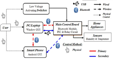
The ultimate goal of the proposed work provides help and assistance to disabled and elderly to manage electrical equipment’s function remotely by smart phone. In order to provide safety protection to the user, a low voltage activating switches is replaced current electrical switches. who can use their voice only to do several works[1]. Speech Recognition is a fascinating field spanning several areas of computer science and mathematics. Reliable speech recognition is a hard problem, requiring a combination of many complex techniques; however modern methods have been able to achieve an impressive degree of accuracy. Speech recognition is the process by which a computer (or other type of machine) identifies spoken words. Basically, it means talking to your computer, and having it correctly recognized what you are saying. Voice or speech recognition is the ability of a machine or program to receive and interpret dictation, or to understand and carry out spoken commands[2]. This system is designed to assist and provide support in order to fulfil the needs of elderly and disabled in home. Also, the smart home concept in the system improves the standard living at home. The main control system implements wireless Bluetooth technology to provide remote access from PC/laptop or smart phone. The design remains the existing electrical switches and provides more
safety control on the switches with low voltage activating method. The switches status is synchronized in all the control system whereby every user interface indicates the real time existing switches status. The system intended to control electrical appliances and devices in house with relatively low-cost design, user-friendly interface and ease of installation. Due to the advancement of wireless technology, there are several different of connections are introduced such as GSM, WIFI, ZIGBEE, and Bluetooth. Each of the connection has their own unique specifications and applications. Among the four popular wireless connections that often implemented in HAS project, Bluetooth is being chosen with its suitable capability. Bluetooth with globally available frequencies of 2400Hz is able to provide connectivity up to 100 meters at speed of up to 3Mbps depending on the Bluetooth device class. In addition, a Bluetooth master device is able to connect up to 7 devices in a “Piconet”[3]. The capabilities of Bluetooth are more than enough to be implemented in the design. Also, most of the current laptop/notebook or cell phones are come with built-in Bluetooth adapter. It will indirectly reduce the cost of this system. In order improve the standard living in home, this system provides three different types of physical control methods to the Main Control Board. The first physical control method is by pressing on the modified Low Voltage Activating Switches. The conventional high voltages switches will be replaced by the modified 5 Volt push buttons as the activating switches. The low voltage switch eliminates the risk of dangerous electrical shock by wet hand. The second and third control methods are performed as wireless remote control to the appliances. The second control method is by clicking on Window GUI on PC/laptop by using mouse or touch pad[3]. This method provides facility to the computer user to control the home appliances without walk to the switches on the wall. Third control method is done by Android GUI installed in Smart Phone. The user can easily touch on the screen of the phone to control the home appliances. This portable method is able to assist the disabled people who have problem with locomotion difficulty.
II. CASE STUDY
ISSN 2250-3153
adult male voice, so Rex would not respond to women or children unless they used a different vowel, like [i] or [I], or even [u] or [U]. They would have to call him “Reeks” or “Riks” or “Rooks” or “Ruks” in order to get the first formant low enough. I bet you have to say it really loud, too. Praat (also the Dutch word for “talk”) is a free scientific software program for the analysis of speech in phonetics. It has been designed and continuously developed by Paul Boersma and David Weenink of the University of Amsterdam. It can run on a wide range of operating systems, including various Unix versions, Mac and Microsoft Windows (95, 98, NT4, ME, 2000, XP, Vista). The program also supports speech synthesis, including articulatory synthesis. Of course, the toy dog mechanism described above is nowhere near automatic speech recognition that we are used to see nowadays, it does not recognize specifically anyone’s voice or converts speech to text that can be processed, but rather simply reacts to a frequency interval regardless of the person who can produce it. Nevertheless, it is exciting for me to have learned that such an interesting toy existed in 1920s and surprised lots of kids. I should also note that the first scientific description of the toy seems to occur in an article from 1962 and I read about it in a modern language processing book in 2011. If this does not feel like a mini time-travel then I guess nothing does [#30]. In the early days of computers, we all learned a congeries of theorems by Turing and von Neumann which told us (or so we thought) that a computer could do anything we told it. We would merely (!) have to specify sufficiently accurately just what it was we wanted the machine to do. And it is true that some highly variable input signals can be categorized by elaborate, exhaustive programs, but it is just not feasible thus to program recognition of printing, speech, handwriting, radar and sonar signals, and objects in photographs (clouds in satellite weather pictures, for example). In the early 1960s, IBM developed and demonstrated "Shoebox" -- a forerunner of today's voice recognition systems. Dr. E. A. Quade, manager of the advanced technology group in IBM's Advanced Systems Development Laboratory in San Jose, Calif., demonstrates Shoebox, an experimental machine that performed arithmetic on voice command. This innovative device recognized and responded to 16 spoken words, including the ten digits from "0" through "9." When a number and command words such as "plus," "minus" and "total" were spoken, Shoebox instructed an adding machine to calculate and print answers to simple arithmetic problems. Shoebox was operated by speaking into a microphone, which converted voice sounds into electrical impulses. A measuring circuit classified these impulses according to various types of sounds and activated the attached adding machine through a relay system. Shoebox was developed by William C. Dersch at IBM's Advanced Systems Development Division Laboratory in San Jose, Calif. He later demonstrated it to the public on television and at the IBM Pavilion of the 1962 World's Fair in Seattle. IBM engineer William C. Dersch, shown above in 1961, demonstrates Shoebox, an experimental machine that performed arithmetic on voice command [#31]. The most significant leap forward of the time came in 1971, when the US Department of Defense’s research agency Darpa funded five years of a Speech Understanding Research program, aiming to reach a minimum vocabulary of 1,000 words. A number of companies and academia including IBM, Carnegie Mellon University (CMU) and Stanford Research Institute took part in the program. That’s how Harpy, built at CMU, was born. Unlike its
predecessors, Harpy could recognize entire sentences. “We don’t want to look things up in dictionaries – so I wanted to build a machine to translate speech, so that when you speak in one language, it would convert what you say into text, then do machine translation to synthesize the text, all in one,” says Alexander Waibel, a computer science professor at Carnegie Mellon who worked on Harpy and another CMU machine, Hearsay-II. All in all, Harpy recognized 1,011 words – approximately the vocabulary of an average three-year-old – with reasonable accuracy, thus achieving Darpa’s original goal. It “became a true progenitor to more modern systems”, says Jaime Carbonell, director of the Language Technologies Institute at CMU, being “the first system that successfully used a language model to determine which sequences of words made sense together, and thus reduce speech recognition errors” [#32].
2.1 Hidden Markov Model Notation:
λ = (A, B, π), is shorthand notation for an HMM.
Other notation is used in Hidden MarkovModels:
A = state transition probabilities ( )
B = observation probability matrix ( (k))
N = number of states in the model {1,2…N} or the state at time t →
M = number of distinct observation symbols per state
Q = { , , . . ., } = distinct states of the Markov
process
T = length of the observation sequence
V = {0, 1, . . ., M − 1} = set of possible observations
O = ( , , . . ., ) = observation sequence
π = initial state distribution ( )
s = state or state sequence ( , , … )
= hidden state
= observation
Three basic problems can be solved with Hidden Markov Models
1. Given the Hidden Markov Model λ = (A, B, π) and a sequence of observations O, find the probability of an observation P (O | λ). This is sometimes called the
Evaluation Problem.
2. Given the Hidden Markov Model λ = (A, B, π) and an observation sequence O, find the most likely state sequence ( , , … ). This is sometimes called a
Decoding Problem.
3. Find an observation sequence ( , , … ) and Hidden
ISSN 2250-3153
[image:3.595.67.262.94.198.2]probability of O. This is sometimes called a Learning Problem or Optimization Problem.
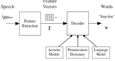
Figure 1: Architecture of an HMM-based Recognizer
The foundations of modern HMM-based continuous speech recognition technology were laid down in the 1970’s by groups at Carnegie-Mellon and IBM who introduced the use of discrete density HMMs and then later at Bell Labs where continuous density HMMs were introduced. Reflecting the computational power of the time, initial development in the 1980’s focused on either discrete word speaker dependent large vocabulary systems or whole word small vocabulary speaker independent applications. In the early 90’s, attention switched to continuous speaker-independent recognition. Starting with the artificial 1000-word Resource Management task, the technology developed rapidly and by the mid-1990’s, reasonable accuracy was being achieved for unrestricted speaker independent dictation. Much of this development was driven by a series of DARPA and NSA programs which set ever more challenging tasks culminating most recently in systems for multilingual transcription of broadcast news programs and for spontaneous telephone conversations. The principal components of a large vocabulary continuous speech recognizer are illustrated in Equation 1.
The input audio waveform from a microphone is converted into a sequence of fixed size acoustic vectors
= , . . ., in a process called feature extraction.
The decoder then attempts to find the sequence of words = ,..., which is most likely to have generated Y,
i.e. the decoder tries to find
Equation 1
However, since P(w|Y) is difficult to model directly,1 Bayes’ Rule is used to transform Equation1 into the equivalent problem of finding:
Equation 2
The likelihood P(Y |w) is determined by an acoustic model and the prior P(w) is determined by a language model.2 The basic unit of sound represented by the acoustic model is the phone. For example, the word “bat” is composed of three phones /b/ /ae/ /t/. About 40 such phones are required for English. For any given w, the corresponding acoustic model is synthesized by concatenating phone models to make words as defined by a pronunciation dictionary. The parameters of these phone models are estimated from training data consisting of speech waveforms and their orthographic transcriptions. The language model is typically an N-gram model in which the probability of
each word is conditioned only on its N − 1 predecessors. The
N-gram parameters are estimated by counting N-tuples in appropriate text corpora. The decoder operates by searching through all possible word sequences using pruning to remove unlikely hypotheses thereby keeping the search tractable. When the end of the utterance is reached, the most likely word sequence is output. Alternatively, modern decoders can generate lattices containing a compact representation of the most likely hypotheses [Gales, 2008 #33].
III. REVIEW OF LITERATURE
ISSN 2250-3153
them and the chances of other wireless networks interfering with Bluetooth are very low. The disadvantage of Bluetooth is that the battery usage during a single transfer is negligible, but if Bluetooth is kept on whole day, then battery loss is significant and because of this it inevitably eats into the battery of these devices, and lowers the battery life considerably. The other disadvantage of Bluetooth is that the security in Bluetooth is good but it is much better in infrared technology. In his Review paper Alam, Reaz [4] et al., (2012) on the topic “A Review of Smart Homes – Past, Present, and Future” identifies several future directions of smart home research. And predicted the trends indicate the increasing popularity of using middleware to integrate heterogeneous devices. Because multivendor devices will coexist in future, the use of middleware is an efficient solution to create networks that will overcome the limitations of diverse device integration. It seems that home intelligence will be employed in a distributed manner. This distributed intelligence may be applied in the form of smart devices.
IV. OVERVIEW
Biometrics is the science of identifying, or verifying the identity of a person based on physiological or/and behavioural characteristics.
Physiological characteristics: Fingerprint, Palmprint, Face, Iris, Retinal scan etc.
Behavioural characteristics: Signature, Keystroke dynamics,
Voice, Gesture
Microprocessor (MPU): A microprocessor is a general-purpose digital computer central processing unit (CPU). Although popularly known as a “computer on a chip” is in no sense a complete digital computer which contains an arithmetic and logical unit (ALU), a program counter (PC), a stack pointer (SP), some working registers, a clock timing circuit, and interrupt circuits. Microprocessors contain no RAM, no ROM, and no I/O ports on the chip itself. For this reason, they are commonly referred to as general-purpose microprocessors. Every microprocessor must have memory space to store Program(Code) and Data. While Code provides instructions to the CPU, the Data provides the information to be processed. The CPU uses buses (wire traces) to access the code ROM and data RAM memory spaces. The early computers used the same bus for accessing both the code and data. Such an architecture is commonly referred to as von-Neumann (Princeton)
[image:4.595.308.555.403.613.2]architecture. That means for Von Neumann computers, the process of accessing the code or data could cause them to get in each other’s way and slow down the processing speed of the CPU, because each had to wait for the other to finish fetching[9]. To speed up the process of program execution, some CPUs use Harvard architecture. In Harvard architecture, we have separate buses for the code and data memory.
Figure 2: Microprocessor Architectures
This is easy to implement inside an IC chip such as a microcontroller where both ROM code and data RAM are internal(on-chip) and distances are on the micron and millimeter scale. But implementing Harvard architecture for systems such as x86 IBM PC-Type computers is very expensive because the RAM and ROM that hold code and data are external to the CPU. Separate wires traces for data and code on the motherboard will make the board large and expensive. For example, for a Pentium microprocessor with a 64-bit data bus and a 32-bit address bus we will need about 100 wires traces on the motherboard if it is a Von Neumann architecture (96 for address and data, plus a few others for control signals of read and write and so on) but the number of wires traces will double to 200 if we use Harvard architecture. Harvard architecture will also necessitate a large number of pins coming out of the microprocessor itself. For this reason we do not see Harvard architecture implemented in the world of PCs and workstations. This is also the reason that microcontrollers such as AVR use Harvard architecture internally[9], but they still use von Neumann architecture if they need external memory for code and data space. The von Neumann architecture was developed at Princeton University, while the Harvard architecture was the work of Harvard University.
Microcontroller (MCU): The design incorporates all of the features found in micro-processor with added features needed to make a complete computer: ROM, RAM, parallel I/O, serial I/O, counters, and clock circuit.
[image:4.595.48.276.667.762.2]4.1Types of Microcontrollers
Figure 3: Types of Microcontrollers, Mazidi, Naimi [9]
4.2AVR Microcontrollers
AVR stand for Alf Vegard RISC is a modified Harvard architecture, 8-bit RISC, single chip microcontroller which was designed by two student of Norwegian Institute of Technology[9] , Alf-Egil Bogen and Vegard Wollan and then was developed by Atmel in 1996. The AVR was one of the first microcontroller families to use on-chip flash memory for program storage, as opposed to OTP ROM, EPROM or EEPROM used by other microcontrollers at that time.
ISSN 2250-3153
[image:5.595.51.274.59.343.2]
Figure 4: Block Diagram of AVR Microcontroller
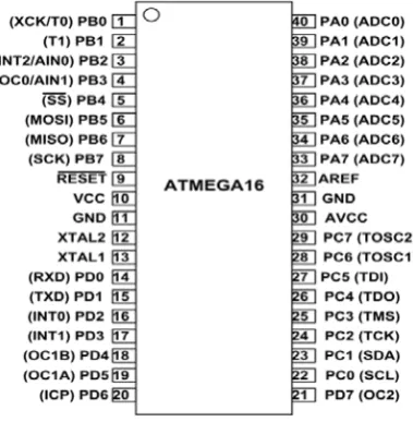
Pin Diagram of ATmega16 Microcontroller Chip
Figure 5: Pin Diagram of ATMEGA16
4.3Embedded systems
An embedded system is a special purpose system in which the computer is completely encapsulated by the device it controls. Unlike a general-purpose computer, such as a PC, an embedded system performs predefined task’s usually with very specific tasks design engineers can optimize it reducing the size and cost of the product. Embedded systems are often mass produced, so the cost savings may be multiplied by millions of items. The core of any embedded system is formed by one or several microprocessor or micro controller programmed to perform a small number of tasks. In contrast to a general-purpose computer, which can run any software application, the user chooses, the software on an embedded system is
semi-permanent, so it is often called firmware. Due to their compact size, low cost and simple design aspects made embedded systems very popular and encroached into human lives and have become indispensable. They are found everywhere from kitchen ware to space craft. To emphasize this idea here are some illustrations.
It’s not same as Robotics but the word Robotics is used to collectively define a field in engineering that covers the Mimicking of various human characteristics. A Robot which may consists of characteristics like mobility, sensibility, programmability, mechanical capacity, involves the knowledge of Mechanical, Electrical & Electronics, and Computer Science Engineering.
V. AVR PROGRAMMING
For performing different task on the computer, a compiler is communication medium that translate source language into target language. Compiler allows the user to perform customized task on machine. Initially for writing compiler machine language was used. After some development assembly language and these days high level language are used for writing compiler. We need compiler because it allows us to communicate with hardware. It also uses to cover the “GAP” between Humans and the Computer language. Computer can understand only one language that i.e., binary language consists of only two digits they are 0 and 1. Binary language is also called machine language. When there is only Machine language then Programmers write their compilers in this language. But it is very difficult and tedious job. The role of compiler is taking source code written in high level language (Java, C++, VB.net etc.). The high-level languages are easily understood by humans. So, compiler converts the program written in source language into machine languages. As we know that computers can easily understand machine language. There are different programs related to compiler that works before compilation such as editor, preprocessor, assembler, linker or loader, debugger and profiler. Therefore, programming is very much essential for an embedded system. Now, as we know there are so many languages and software (CV, AVR, Win AVR, AVR Studio etc.) are available for programming. So, here we’ll be doing programming in Embedded C, we are calling it because it’ll be having some logics from C and some from C++. So, for writing program we should have notepad and then we’ll write code on that and will compile that code by using a compiler named AVR GCC. Compiler compiles that code and some other files generate, in those files there’ll also be HEX file as we know that our microcontroller understands on 0 and 1 logics only so this Hex code will be helpful now for burning our program in our hardware (controller).
VI. COMMUNICATION
Communication is the process which defines the conveying the information from one end to another end. In terms of electronic communication, it can be of two types:
[image:5.595.86.276.393.587.2]ISSN 2250-3153
Figure 6: Communication through Control board
Communication is the transmission & reception of any signal, which may be digital or analog. We are here going to describe about the digital data transmission.
Digital transmission can occur in two ways:
a) Serial Data Communication: In this method of communication, the data transmission is in one bit at a time through the medium(wire).
b) Parallel Data Communication: In this method of communication, the data is transmitted in one block at a time.
6.1.USART using RS-232 Protocol
A USART (Universal Synchronous/Asynchronous
Receiver/Transmitter) is a microchip that facilitates communication through a computer's serial port using the RS-232C protocol. USART is a protocol for transferring data serially. The serial data can be transferred in two modes using USART (Synchronous and Asynchronous mode). Like a UART (Universal Asynchronous Receiver/Transmitter), a USART provides the computer with the interface necessary for communication with modems and other serial devices. However, unlike a UART, a USART offers the option of synchronous mode. In program-to-program communication, the synchronous mode requires that each end of an exchange respond in turn without initiating a new communication. Asynchronous operation means that a process operates independently of other processes. Practical differences between synchronous mode (which is possible only with a USART) and asynchronous mode (which is possible with either a UART or a USART) can be outlined as follows:
• Synchronous mode requires both data and a clock. Asynchronous mode requires only data.
• In synchronous mode, the data is transmitted at a fixed rate. In asynchronous mode, the data does not have to be transmitted at a fixed rate.
• Synchronous data is normally transmitted in the form of blocks, while asynchronous data is normally transmitted one byte at a time.
• Synchronous mode allows for a higher DTR (data transfer rate) than asynchronous mode does, if all other factors are held constant.
One advantage is the fact that the physical line for the clock is not needed. Also, asynchronous communication is better over long distances. If we try to synchronize a remote receiver by sending the clock signal, due to propagation delays and
interference, the validity of the clock is lost. The two devices (AVR microcontroller and our PC) operating at two different clock frequencies and different logic levels. The problem faced, when the two devices will try to communicate are:
• Frequency • Logic level
The first problem is solved by using a proper Baud rate and the remedy to the second problem is, use of logic converter ICs.
Baud rate: In telecommunication and electronics, is the unit for symbol rate or modulation rate in symbols per second or pulses per second. It is the number of distinct symbol changes (signaling events) made to the transmission medium per second in a digitally modulated signal or a line code.
logic converter ICs: This compact circuit makes it perfect for embedded systems that need to interface with different logic levels. The design is based on 74LCX 245 IC, which is a low voltage bidirectional transceiver with 5V tolerant inputs and outputs, from Fairchild.
Registers of USART
a. UDR (USART Data Register)
b. UCSR (USART Control and Status Register) i. UCSRA
ii. UCSRB iii. UCSRC
c. UBRR (USART Baud Rate Register)
6.2.Bluetooth
Bluetooth is an open wireless technology standard for exchanging data over short distances, from fixed and mobile devices using radio transmission. Bluetooth technology allows electronic devices to communicate wirelessly. It allows you to share voice, data, music, photos, videos and other information wirelessly between paired devices. It delivers the received data and receives the data to be transmitted to and from a host system through a Host Controller Interface (HCI). The most popular host controller interface today is either is UART or a USB. Here, we will only focus on the UART interface. Mobile phones, FM radio and Television all use radio waves to send information wirelessly. And while Bluetooth technology also uses radio waves, it transmits them over a shorter distance. Radios and TV broadcast over many miles or kilometers. Bluetooth technology sends information within your Personal Area Network (PAN), at a distance up to 100 meters (328 feet), depending device implementation. Bluetooth technology operates in the unlicensed industrial, scientific and medical (ISM) band at 2.4 to 2.485 GHz, using a spread spectrum, frequency hopping, full duplex signal at a normal rate of 1600hops/sec. Bluetooth device are managed using an RF topology known as a “Star topology.” A group of devices are synchronized in this fashion forms a piconet, which may contain one master and up to seven active slaves, with additional slaves that are not actively participating in the network.
ISSN 2250-3153
The modules with the HC_04 and HC-06 firmware are the modules which are factory set to be Master or Slave modules. Master and Slave mode cannot be switched from the factory setting. HC-04 is an industrial grade product; HC-06 is a commercial grade product. The voltage to be applied to these modules is from a minimum of 3.1 V DC to a maximum of 4.2 V DC for 05/06 and a maximum of 3.6 V DC for HC-09.
Figure 7: Bluetooth Module (HC-05)
Do not connect 5V DC or more unless you are using the module mounted on a board which includes some sort of voltage regulation. The serial output is at TTL voltage levels (3.3 V to 5V) and not the higher RS232 voltage levels (12V+). Do not connect the module directly to your computer serial port unless the module is mounted on a board that is doing TTL to RS232 conversion[10]. You can also use a TTL to TS232 adapted to connect the module to your computer serial port. You do not need to use any conversion if you are connecting the module to your microcontroller serial port which has 5V DC tolerant pins.
6.3.Speech Recognition Techniques
The most natural way to communicate for human beings is through words. Human respiratory and articulator systems which consist of different organs and muscles generate speech. Coordinated action of these speech production organs creates speech. The speech or voice can be categorized in many ways. In general, the following ways are mainly analyzed: acoustic, phonetic, phonological, morphological, syntactic, semantic and pragmatic. These levels are used or being processed in the way of converting text to speech. Furthermore, communication in spoken language can be divided as linguistic and paralinguistic. Paralinguistic information is considered as information about the speaker, way how words are spoken, and the factors during speech like breathing, speed, intonation, hesitation etc. and linguistic is considered as the actual meaning of word. Mainly Paralinguistic is the way of communication and linguistic is the information conveyed during communication.
Let’s take a look at the History of ASR
• RADIO REX (1922) 500Hz acoustic energy.
• IBM SHOEBOX – 1961, Digit Recognizer, 16-word vocab. • HARPY system developed at CMU -1976, 1000-word
vocabulary, Used FST with nodes representing Words and Phones.
• HIDDEN MARKOV MODELS(HMM)-1980s (still being used).
Over the past 20 years several developers and designers has improved the way of converting speech to text in real time. It is
their hard work that we are able to convert speech to text. The developments are done by improving technologies, computer systems and communication ways. These parallel developments led the way to the applications we use today for converting speech into text. Automatic speech recognition, translating of spoken words into text, is still a challenging task due to the high viability in speech signals. For example, speakers may have different accents, dialects, or pronunciations, and speak in different styles, at different rates, and in different emotional states. The presence of environmental noise, reverberation, different microphones and recording devices results in additional variability. Conventional speech recognition systems utilize Gaussian mixture model (GMM) based hidden Markov models (HMMs) to represent the sequential structure of speech signals. HMMs are used in speech recognition because a speech signal can be viewed as a piecewise stationary signal or a short-time stationary signal. In a short time-scale, speech can be approximated as a stationary process. Speech can be thought of as a Markov model for many stochastic purposes. Typically, each HMM state utilizes a mixture of Gaussian to model a spectral representation of the sound wave. HMMs-based speech recognition systems can be trained automatically and are simple and computationally feasible to use. However, one of the main drawbacks of Gaussian mixture models is that they are statistically inefficient for modeling data that lie on or near a non-linear manifold in the data space. Neural networks trained by back-propagation error derivatives emerged as an attractive acoustic modeling approach for speech recognition in the late 1980s. In contrast to HMMs, neural networks make no assumptions about feature statistical properties. When used to estimate the probabilities of a speech feature segment, neural networks allow discriminative training in a natural and efficient manner. However, in spite of their effectiveness in classifying short-time units such as individual phones and isolated words, neural networks are rarely successful for continuous recognition tasks, largely because of their lack of ability to model temporal dependencies. Thus, one alternative approach is to use neural networks as a pre-processing e.g. feature transformation, dimensionality reduction for the HMM based recognition. Deep learning, sometimes referred as representation learning or unsupervised feature learning, is a new area of machine learning. Deep learning is becoming a mainstream technology for speech recognition and has successfully replaced Gaussian mixtures for speech recognition and feature coding at an increasingly larger scale.
Imagine a situation,
Weather:
• RAINY • SUNNY
Work:
ISSN 2250-3153
We can ask three questions:
1. Evaluation Problem: If I know your sequence of work for the last few days, how likely it is that you might take a ‘WALK’ when it is ‘RAINY’?
2. Decoding Problem: If I know your sequence of work for the last few days, what is the most likely sequence of weather conditions?
3. Learning Problem: If I know your sequence of work and the sequence of WEATHER conditions for the last few days, what might be the weather condition for the next day?
But how does it help in speech recognition?
Work ⇔ Audio signal frames
Weather Conditions ⇔ Phonemes
Forward Backward Algorithms
VITERBI
EM ALGO
6.4.Adaptive Multi-Rate Audio Codec
The Adaptive Multi-Rate (AMR, AMR-NB or GSM-AMR) audio codec is an audio compression format optimized for speech coding. AMR speech codec consists of a multi-rate narrowband speech codec that encodes narrowband (200–3400 Hz) signals at variable bit rates ranging from 4.75 to 12.2 kbit/s with toll quality speech starting at 7.4 kbit/s. AMR was adopted as the standard speech codec by 3GPP in October 1999 and is now widely used in GSM and UMTS. It uses link adaptation to select from one of eight different bit rates based on link conditions. AMR is also a file format for storing spoken audio using the AMR codec. Many modern mobile telephone handsets can store short audio recordings in the AMR format, and both free and proprietary programs exist (see Software support) to convert between this and other formats, although AMR is a speech format and is unlikely to give ideal results for other audio. The common filename extension is amr. There also exists another storage format for AMR that is suitable for applications with more advanced demands on the storage format, like random access or synchronization with video. This format is the 3GPP-specified 3GP container format based on ISO base media file format.
VII. SYSTEM DESIGN
7.1Write Codes
We will write our codes in AVR Studio. It is created by Atmel in order to create applications for microcontrollers using C/C++ programming languages with the AVRLib, which is essentially a collection of functions and macros that make accessing the functionality of the AVR microprocessor easier and more intuitive. The functions tend to have intuitive names, and follow a naming convention of
[image:8.595.60.245.66.244.2]filenameActionToPerform(), where filename is the descriptive name, beginning with a lowercase letter of the .c and .h file in which the function is contained (e.g. timer for timer functions or a2d for analog-to-digital conversion functions). The ActionToPerform() portion of the name normally describes what the function does. Most AVRLib files have an initialization function which must be called before the other functions for that file can be used, for example timerInit(), uartInit() and midiInit() [14].
Figure 8: AVR Studio Snapshot
7.2Layout Designing and Simulation
Proteus (ISIS) is a Virtual System Modelling and circuit simulation application. The suite combines mixed mode SPICE circuit simulation, animated components and microprocessor models to facilitate co-simulation of complete microcontroller based designs. Proteus also has the ability to simulate the interaction between software running on a microcontroller and any analog or digital electronics connected to it. It simulates Input / Output ports, interrupts, timers, USARTs and all other peripherals present on each supported processor[15].
Figure 9: Simulation Snapshot
[image:8.595.307.547.281.435.2]ISSN 2250-3153
Build your project and generate a hex file, but before going to burn the program make modifications if needed.
7.4Design PCB Layouts: Express PCB
Drawing a schematic with the ExpressSCH program is as easy as placing the components on the page and wiring the pins together. The schematic can then be linked to your PCB file, so that the PCB knows what needs to be connected together.
7.5Build PCB
Printing, transferring artwork, Etching & Drilling.
7.6Burn Program to Microcontroller
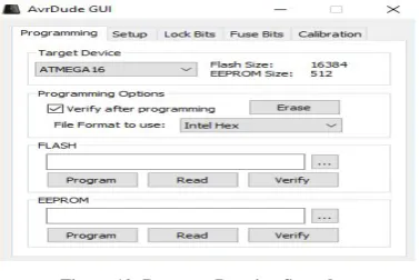
[image:9.595.70.259.283.409.2]These AVR programmers are based on Thomas Fischl's USBasp design and connect to your computer's USB port. Not only are they quite compact (70x20mm), but the design is really elegant. The USB interface is achieved by using an atmega8 processor and the rest is done in firmware.
Figure 10: Program Burning Snapshot
7.7Check External Device Communications
The X-CTU software is easy to use and allows MaxStream customers to test the radio modems in the actual environment with just a computer and the items included with the radio modems[16].
Main features:
1) Support for all MaxStream products. - Integrated terminal window.
2) Easy to use loop back range test.
3) Display of Receive Signal Strength Indictator (RSSI).
4) Upgrade RF module firmware in the field on all XCite modules and XStream modules version 4.29 and higher.
5) Display both ASCII and hexadecimal characters in terminal window.
6) Compose test packets in either ASCII or hexadecimal for transmitting in terminal interface.
7) Save and retrieve commonly used module configurations (profiles).
8) Automatically detect module type.
9) Restore factory default parameters.
10)Display help about each of the radio parameters.
11)Program radio profiles in a production environment using command line interface.
12)Integrate with Labview and other production test software through command line interface[16].
Figure 11: External Communication Snapshot
7.8Real life testing: We Should Check our Embedded system in real life scenario and mark out errors.
7.9 Flow Chart:
VIII. SYSTEM PROTOTYPE
CONCLUSION
ISSN 2250-3153
created to allow user’s control over home appliances from a remote distance. One of the controllable platforms is the Android device that controls Speech to text and the text are treated as Commands for home appliances by connecting to the main server. The main server, which can also control home appliances, is also programmed to perform commands received from the email to control appliances. Apart from that, users may prompt for appliances condition also through email and the reply can be sent to the user’s email address or phone number through SMS with the help of GSM Module that can integrate with the proposed prototype. All the features stated above has fulfilled the project objective to design a smart system that allows remote controlling of home appliances.
REFERENCES
1. Sonawane, N.K., P.D. Waghchavare, and K.A. Patel, Bluetooth based device automation system using cellphone. International Journal of Computer Applications & Information Technology, 2014. 7(1).
2. Rudrapal, D., et al., Voice recognition and authentication as a proficient biometric tool and its application in online exam for PH people. International Journal of Computer Applications, 2012. 39(12).
3. Ramlee, R.A., et al., Bluetooth remote home automation system using android application. The International Journal of Engineering And Science, 2013. 2(1): p. 149-153.
4. Alam, M.R., M.B.I. Reaz, and M.A.M. Ali, A review of smart homes—Past, present, and future. IEEE Transactions on Systems, Man, and Cybernetics, Part C (Applications and Reviews), 2012. 42(6): p. 1190-1203.
5. Nikam, D., et al., Voice Controlled Wheelchair Using AVR. International Journal of Modern Trends in Engineering and Research, Scientific Journal Impact Factor (SJIF), 2015. 1.
6. Baig, F., S. Beg, and M.F. Khan, Controlling home appliances remotely through voice command, in arXiv preprint arXiv:1212.1790. 2012.
7. Nisar, K. and A.A.A. Ibrahim. A Smart Home Model Using Android Application. in International Conference on Kansei Engineering & Emotion Research. 2018. Springer.
8. Rana, M. and R. Singh, Smart Homes for a better living using Bluetooth communication based on ATmega Microcontroller''. International Journal of Research in Engineering and Technology, 2014. 3(6): p. 210-213.
9. Mazidi, M.A., S. Naimi, and S. Naimi, AVR microcontroller and embedded systems: using assembly and C. 2010: Prentice Hall Press.
10.
http://www.agrident.com/download/files/APR500_Bluetooth_Ma nual_eng.pdf.
11. http://www.digitalcitizen.life/enabling-remote-desktop-connections-windows-7.
12. http://www.engineersgarage.com/tutorials/how-to-make-a-pcb-at-home.
13.
http://www.atmel.com/webdoc/atmelstudio/atmelstudio.Introduct ion.InstallationUpdate.Requirements.html.
14. https://ccrma.stanford.edu/wiki/AVR_Programming.
15. http://www.r4systems.com/Downloads/Proteus_Intro.pdf. 16. http://x-ctu.software.informer.com/.
17. https://ileriseviye.wordpress.com/2011/02/17/speech-recognition-in-1920s-radio-rex-the-first-speech-recognition-machine/, #30
18.
https://www03.ibm.com/ibm/history/exhibits/specialprod1/specialp rod1_7.html, #31
19. http://www.bbc.com/future/story/20170214-the-machines-that-learned-to-listen, #32
20. Pardue, J., C programming for microcontrollers. Smiley micros, 2005. 46.
21. Sivakumar, M.S., et al. Speech controlled automatic wheelchair. in Information Science, Computing and Telecommunications (PACT), 2013 Pan African International Conference on. 2013. IEEE. 22. Davidovic, B. and A. Labus, A smart home system based on sensor
technology. Facta Universitatis, Series: Electronics and Energetics, 2015. 29(3): p. 451-460.
23. Tandon, A., et al., AVR Development Board. International Journal of Engineering and Management Research (IJEMR), 2017. 7(2): p. 585-588.
24. Varatharajan, S.K. and V. Nallasamy, Voice Based Home Automation Using Bitvoicer. 2017.
25. Parashar, S., et al., Advance IOT Based Home Automation. 2018.
AUTHORS
1Bharat Kumar Dhal has degrees MSc. in Computer Science (Specialized in
Artificial Intelligence) from Central University of Rajasthan (CURAJ), Ajmer, Rajasthan and BSc. from Ravenshaw University, Cuttack, Odisha. Completed his XII from B.J.B Junior College, Bhubaneswar. He had been working for TechieNest Co., Jaipur for six months as a software developer on Internet of Things (IoT) & Embedded Systems for the fulfilment of Masters Project thesis. Attended Workshop for showing own Prototype Called “SMART CAMPUS” based on IoT concept at IIT Delhi during TechFest. He is just submitted his M.Phil. Thesis at Dept. of Information & Communication Technology, Fakir Mohan University (FM), Balasore. His Current field of research is Soft Computing & Pattern Recognitions.
GUIDEDr. Ashanta R. Routray, Reader is a lecturer
![Figure 3: Types of Microcontrollers, Mazidi, Naimi [9]](https://thumb-us.123doks.com/thumbv2/123dok_us/9059190.977580/4.595.48.276.667.762/figure-types-of-microcontrollers-mazidi-naimi.webp)