University of East London Institutional Repository:
http://roar.uel.ac.uk
This paper is made available online in accordance with publisher policies. Please
scroll down to view the document itself. Please refer to the repository record for this
item and our policy information available from the repository home page for further
information.
Author(s):
Brown, T. John; Gawley, Rachel; Spence, Ivor; Kilpatrick, Peter; Gillan,
Charles; Bashroush, Rabih.
Article title: Requirements Modelling and Design Notations for Software Product
Lines
Year of publication:
2007
Citation:
Brown, T.J. et al. (2007) ‘Requirements Modelling and Design Notations
for Software Product Lines.’ Proceedings of the First International Workshop on
Variability Modelling of Software-intensive Systems (VaMoS2007), Lemrick, Ireland,
Jan 16-18, 2007.
Link to published version:
Requirements Modelling and Design Notations for Software Product Lines.
T.J.Brown, R. Gawley, I. Spence, P. Kilpatrick, C. Gillan, R. Bashroush
.School of Electronics, Electrical Engineering and Computer Science,
The Queen’s University of Belfast.
{r.gawley, tj.brown , i.spence, p.kilpatrick @qub.ac.uk
{C.Gillan, R. Bashroush}@ecit.qub.ac.uk
Abstract
Although feature modelling is a frequently used approach to the task of modelling commonality and variability within product lines, there is currently no standard modelling notation or methodology. On the assumption that the commonality/variability model will be used as a basis for architecture design, our modelling notation allows features to be augmented with behavioural detail, captured using the UCM path notation. This gives rise to models that capture commonality and variability in behaviour as well as in product features, and are thus more valuable for downstream design activities. This paper outlines the modelling notation and describes ongoing work on the characterisation of variability points within models based on this notation, and on the relationships between model fragments and solution domain techniques such as design patterns or variability realisation techniques. It also describes preliminary work, aimed at evolving an intelligent tool that can characterise feature and behavioural model fragments and suggest design and realisation methods.
Keywords:Feature diagram, Modelling language, UML
1. Introduction
Software Product Line engineering [1] aims to maximise reuse within a family of related systems, by exploiting the commonalities across the family, while at the same time managing and accommodating the variability. The successful analysis and modelling of commonality and variability is therefore a crucial early-stage activity within software product line engineering. The most widely used approach to the capture of commonality and variability makes use of feature modelling. The basic concepts of feature modelling were introduced by Kang et al in 1990 [2], but have subsequently been revised and extended by many authors. Feature modelling notations and techniques
continue to be the focus of active research with a consequent proliferation of notations and methods. Clearly there is a case for trying to agree on a standard approach to commonality/variability modelling. Equally clearly, there are still some aspects that merit continued investigation.
In this paper we first briefly explore the basics of commonality/variability modelling using feature modelling. We then pose what seems to us a fairly fundamental question relating to the intended role of the commonality variability model within the engineering process. How one answers this question influences the notation and process needed. We describe our own vision of the role that commonality/variability models should play, and discuss our notation which combines both feature and behavioural modelling facilities. We also describe our current research which aims to understand the relationships between variability exposed within the feature and behavioural model and variability realisation techniques. Included among the latter are techniques such as those described in [3,4], along with design patterns, many of which serve to introduce flexibility into software designs. An understanding of these relationships opens up the possibility of creating an architect’s advisor, i.e. an intelligent tool with the ability to analyse the variability it finds within the commonality/variability model for an intended product line, and identify possible design techniques that allow it to be managed.
2. Feature Modelling: Basic Concepts and
Contemporary Developments
Numerous developments have followed. The FORM notation [5,6] made use of layering within the model hierarchy, and. allowed the use of feature groups wherein selection is based on inclusive OR relations. Riebisch et al [7] introduced the idea of using explicit UML style multiplicities to constrain the selection of features from groups, an approach that has been further developed in several papers by Czarnecki et al. [8,9]. Using explicit cardinalities to regulate selection from groups conveys more flexibility than simply using alternative or OR feature groups which become special cases in this situation. More recently cardinality values have been attached to solitary (i.e. non group) features. In this context the cardinality specifies the number of times the features and its sub-tree can be replicated. Several authors have made use of feature properties or attributes. Fey et al [10] made use of the idea of feature properties and introduced two forms of relationship involving features and properties. Czarnecki et al [8,11] use the slightly different concept of attributes. An attribute type can be associated with a feature, indicating that a value of that type can be assigned during configuration, but only one such attribute is allowed per feature. Modularisation of feature models has also been recognised as desirable in practice because feature models are often very large. Bednasch et.al. [12] proposed an approach based on the use of special leaf nodes, while the idea of feature macros can be found in the work of Cechticky et al [13]. The potential value of incorporating behaviour in some way began to be recognised with the work of Mei et al [14]. In their FODM feature modelling notation they discuss the concept of behavioural characteristics attached to features that are recognised as functional in character. In the PLUSS feature modelling approach [15] broadly similar motives have prompted Eriksson et al. to combine features with Use case models and Use Case realisations. As described below the modelling of common and variant behavioural characteristics forms a key element in our approach.
Clearly there is at this time a wide range of approaches to commonality/variability modelling and a corresponding argument for some form of rationalisation.
3. Role of Commonality Variability Models
What should be the role of commonality and variability modelling in product line development? Should it be simply a means of recording and documenting the common and variant aspects of the product line, essentially for the benefit of customers, managers and sales personnel, or should it also play a more significant role in the software design and implementation activities? The answer to this question
will influence the detailed notation and techniques that need to be used to capture the commonality and variability. Software systems are often large and the construction of commonality/variability models for a family of such systems represents a considerable investment in effort. In our approach to commonality/variability modelling we assume implicitly that maximal use should be made of such models once they have been constructed. Thus a commonality/variability model should certainly document the variety of product features and the potential for variability in the features supported within individual products. It should also allow the creation of individual product definitions as valid collections of supported features. Most approaches reported in the literature share these objectives. In our work we also seek to use the model to support the software design process, and in particular the derivation of a generic architecture for the product family.
This aspiration introduces a number of issues. We must think carefully about how we should model commonality and variability, given the objective of using the model to guide architecture development. Identifying mechanisms to handle variability at the architectural and implementation stages is a significant issue in this process. Closely related to this is the question: How can we relate variability points within the model to actual variability realisation techniques? We are beginning to see the cataloguing of variability realisation techniques, for example in the work of Svahnberg et. al. [3], and the more recent work reported in [4]. Moreover, we already have a large literature on design patterns [16]. Many of these represent techniques for introducing flexibility into software designs, which makes them potentially valuable in the context of product line architectures, a point recognised by some authors [17]. It is probably unrealistic to expect that we can reach a stage where variability points manifest within commonality/variability models, can be mapped directly or uniquely to a particular realisation technique, or a particular combination of design patterns. But it would still be very useful to architects to be able to obtain guidance on possible design strategies.
A further issue is how we relate the commonality/variability model to the generic architecture. Linking these two spaces allows us to relate architectural components to the product features that they support. This in turn makes it possible to derive product architectures from individual product feature sets.
4. The QUB Approach
commonality/variability modelling [18] that is based, like most such efforts, on feature modelling, but with facilities for capturing feature behaviour and behavioural variability. For this purpose we have adopted the Use Case Maps (UCM) notation. The UCM path notation [19,20,21,22,23] provides a means of capturing behaviour at an abstract level, independent of any assumed component architecture. A path can be attached to any feature provided the behaviour associated with the feature can be fully represented by a single path. (High level features within the model are assumed to aggregate behaviour associated with their children). As we relate below, having behavioural information allows a more complete characterisation of variability points.
We have also developed a relational architecture description language called ADLARS [24]. This is a notation that supports the description of generic software architectures with embedded relationships between architectural components on the one hand and the supported product features on the other. This allows variant features within the commonality/variability model to be linked, for example, to alternative or optional components within the architecture design. Hence at the application engineering stage, as soon as the feature set for a single product has been defined, it becomes possible to generate the architecture for that product.
We do not discuss ADLARS herein, since it is well documented in several publications. Instead we review the feature and behavioural modelling notation and then go on to describe current research efforts. These are focussed on two closely related problems. The first is to understand how variability points exposed within feature and behavioural models can be related to variability realisation techniques, including design patterns. The second is to identify the technology underpinnings for an ‘intelligent’ tool that could scan feature and behavioural models, abstracting out model fragments that encompass specific variation points and then offer guidance to the software architect on how each variability point could be managed in terms of software design. These are difficult topics and our research on them is at an early stage.
4.1 Feature Modelling Specifics
In common with the original FODA framework, and most subsequent notations, our feature modelling schema allows features to be mandatory, optional or alternative. A mandatory feature will be supported by every product instance that supports it parent. Optional features are features that may be present or absent from any product within the family. Alternative feature sets are sets of features from which only one is selected for
inclusion in any given product. They are thus mutually exclusive: if one is supported the others cannot be. In addition, rationalised feature modelling allows the use of OR features [26]. An OR feature set is a set of features from which one or more may be selected into any product within the family. At least one must be selected but there is no exclusivity relationship, and in fact a product may contain all features within any OR feature set. As in FODA, feature selections may be subject to constraints and the now-standard constraints of mutual exclusion and requirement are supported. Features may also have attached properties and, borrowing from the work of Fey et al. [10], properties may participate in relationships.
4.2. Bi-Directional Feature Modelling
Perhaps the most radical aspect of the core feature modelling scheme is its support for bi-directional models [25]. In this approach a conventional top-down feature tree models features of the family that are software based, or have a software component, and an inverted feature tree models the hardware and operating system platform. The top-down feature tree follows the FORM practice of layering the feature tree. A three-layer model is used with a capability feature three-layer, which models high level product features, a domain technology layer and then an implementation feature layer below.
Fig.1 Screen shot of a bi-directional feature model arising from ALS/APR safety procedure used on Optical Network Products [31]
and the operating system platform. The first form of
across-boundary relationship is that of mutual
dependency between an optional or alternative software feature in the upper feature tree and an operating platform feature. The implication is that the software feature requires or depends on the availability of the platform feature. If an optional platform feature is excluded then the software feature depending on it cannot be provided. Although this may be a low level feature, the implications can extend upwards to the capability feature layer.
The second across-boundary relationship is that of a
hardware-software feature alternative. In this case we
are dealing with the same feature which may be provided in software within one member of the family but in hardware within others. This kind of situation may arise in practice when the first products within an intended family are released with a certain feature provided in software; whereas in later models the feature migrates to a hardware device such as an ASIC, FPGA or DSP (we have encountered this phenomenon with some families of network products). It is worth noting that any kind of feature may participate in this relationship. Thus, we could have a mandatory feature which in some products is provided via software and in others via hardware. Likewise we could have an optional feature which, within some products, may not be provided at all, but if it is provided then it may be provided as either hardware or as software.
4.3. Linking Behaviour to Features
To capture feature behaviour, it is essential to have a suitably abstract notation. There are several well known notations that are often used for modelling behaviour. Within the UML, sequence and collaboration diagrams, Use Case diagrams, and activity diagrams can all be used for behaviour capture. For a number of reasons however [18], we have chosen the Use Case Maps path notation as the most appropriate form of notation.
Use Case Maps, like feature modelling itself, is a requirements capture notation. Its focus is on the capture of behaviour at a reasonable level of detail. The founding concepts of the notation were introduced by Buhr [19] and have subsequently been extensively developed by Amyot and others [21]. Whereas feature modelling is inherently a notation targeted at product-line requirements, UCM was developed as a general purpose requirements modelling notation, aimed at providing an abstract, path-centric view of system functionality. It has now been standardized and integrated into the User Requirements Notation (URN) [23].
4.4. UCM Path Notation
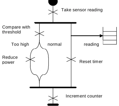
In the UCM notation, behaviour is captured in terms of a causal path. The path begins at a starting point, which may have triggering events and/or pre-conditions associated with it, and it continues to one or more end points, which may have associated resulting events and/or post-conditions. Along the way it may contain responsibility points, representing actions or responsibilities that must be discharged in the sequential order in which they appear. Paths may have loops, OR-forks, which indicate alternative paths, and AND-forks that give rise to concurrent path segments that may be executed in parallel. Alternative paths may be labelled with the conditions that give rise to their selection. Concurrent and alternatives paths may rejoin at an AND-join, or OR-join, respectively. Data items may be created or destroyed and may be placed on, or removed from a path. Data placed on a path is considered to move along the path. The notation supports the concept of a pool, which is a form of generic data store, and data items may be moved into or out of pools. Paths may contain waiting points representing situations where processing is delayed awaiting the arrival of some external event, or the satisfaction of some condition. Synchronization and rendezvous points may also be included. A timer feature allows the introduction of timed path segments, in which execution must complete within a defined time, otherwise the normal execution path is aborted in favour of an alternative error path. In the basic notation a path may cross one or more components. Components need not be shown if no component architecture is available, or they may be included as rectangles.
Take sensor reading
Com pare with threshold
Too high normal
Reduce
power Reset tim er
reading
[image:5.595.326.528.478.657.2]Increm ent counter
Fig. 2 An example illustrating the UCM path notation
assigned to that component. An example of a UCM path is shown in fig. 2.
4.4.1 Static and Dynamic stubs
A very important concept in the UCM notation is the idea of stubs. When a stub is embedded within a path it acts as a placeholder into which further behaviour can be plugged. Graphically a stub is represented as a diamond on the UCM path, and the plug-in behaviour will be represented as another UCM path. Stubs can be of two types. The simplest are called static stubs and only one subsidiary path can be plugged in to them. In this case the plug-in serves as a definition of the behavioural detail at that point within the containing path. The second kind of stub, called a dynamic stub, is characterized by the fact that several alternative plug-in maps may be inserted in them. The UCM concept is that the actual plug-in may be selected at run-time, depending on the satisfaction of associated pre-conditions. Dynamic stubs therefore represent points at which behaviour may vary. However, the plug-ins that may be plug-inserted into either static or dynamic stubs may themselves contain stubs that may in turn be either static or dynamic. So, paths may have stubs for which the plug-ins may contain stubs, essentially to any level of nesting. Clearly this mechanism provides scope for the capture of behavioural variability to any level of detail. This is a very important capability and one that is exploited fully in the integration of Use Case Maps with feature modelling.
4.5 Capturing Feature Behaviour
To add behaviour to a feature, in the simplest case, we attach a UCM path to the feature. We follow the principle that a UCM path will only be attached to a feature if that feature’s associated behaviour can be captured by one unique path. At first sight that might appear to imply that the allocation of behaviour to a feature would preclude the allocation of behaviour to its children. However paths can contain stubs. When a parent feature has a path with stubs, its children can contribute the plug-in behaviour needed. Of course the child feature’s path may also contain stubs which accept behaviour provided by grandchildren. Thus behaviour may be woven into multiple levels within the feature model structure.
5.
Relating
Variability
points
and
Variability Realization Techniques
To derive maximum benefit from the integration of these notations we clearly need to understand how to use the resulting framework to evolve a generic
architecture and ultimately, implementation components. One of the principal difficulties in designing architectures for product lines is the need to accommodate variability from product to product. It is therefore important that the commonality/variability model should allow a clear understanding of the underlying nature of each variability point, and where possible, allow the identification of possible variability realisation methods. The decision to integrate behavioural modelling with feature modelling was prompted by this objective.
A key theme in our current research efforts is the identification of possible variability realisation techniques using information within the feature and behavioural model. Although still at an early stage, factors that we have found to be important include the actual pattern of features in the environment of a variability point, the pattern of allocation of behaviour to those features and the pattern of usage of behavioural elements, such as stubs, within the path definitions. Properties attached to features can also be important. Our long term aim in this endeavour is the creation of an ‘intelligent’ tool with the ability to analyse the content of a commonality/variability model, characterise variability points within the model and offer recommendations on possible realisation techniques. Clearly this is an ambitious objective and much research is still needed. However, the problem is potentially more tractable with the fusion of feature and behavioural information. Some model fragments with mapped behaviour lead fairly readily to realisation strategies. For example, consider a feature model fragment in which a parent feature has an associated path containing a dynamic stub, with as children, an alternative feature group whose member features each have associated paths. A likely interpretation of this situation is a single algorithm with alternative sub-algorithms, only one of which can be selected. A simple pattern, such as the template pattern, could be an appropriate realisation strategy in the case of fine-grained algorithm variability. On the other hand, the same feature model structure, but this time with a parent feature whose associated behaviour could not be represented by a single path, would point to a different realisation strategy, perhaps, for example, the strategy pattern, as a possible realisation mechanism. The feature model fragment has the same structure in both cases, but the pattern of allocation of behaviour is different. As this work has progressed, an emerging issue is the possible advantage in adding some further facilities to the notation. Two new notational concepts that have been identified as potentially useful are those of
5.1. Property bound alternatives
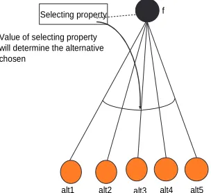
An alternative feature group wherein the alternative chosen depends on some property of its parent feature is what we refer to as a property bound alternative. Graphically this can be represented as shown below in fig 3. Feature ‘f’ is a parent feature with a group of five alternative children. The value of the ‘selecting property’ determines the choice of alternative child feature. An important consideration is that it is often possible to nominate a binding time for feature alternatives. One such option is run-time binding. By implication choice of run-time binding in this situation means that the selecting property is a variable, whose value at run-time will fix the alternative chosen. On the other hand a binding time earlier than run-time will imply that the selecting property is a constant. It is interesting that Svahnberg’s taxonomy of variability realisation techniques [3] includes two mechanisms described as condition on constant and condition on
variable, respectively.
f Selecting property
alt1 alt2 alt3 alt4 alt5 Value of selecting property
will determine the alternative chosen
[image:7.595.72.224.365.504.2]Fig. 3 Illustration of the property bound alternative concept
The most appropriate implementation technique depends on a number of considerations. If each alternative has an attached UCM path (not indicated in the diagram) then a fine-grained variability point is suggested and a simple programming based approach using, for example, a switch construct might be appropriate. On the other hand, if the alternative features do not have attached paths, then by implication we are dealing with coarser grained alternatives. Use of conventional pre-processor directives (#IFDEFs) to include one file or component instead of another represents one possible approach, particularly when the alternatives have compile-time binding. If the alternatives have run-time binding then design patterns like the state pattern can be considered. This discussion both illustrates the potential usefulness of this particular
notational feature, and the way multiple factors impinge on the possible variability realisation strategy chosen.
5.2. Synchronised Alternatives
As described earlier, our modelling notation allows platform features to be modelled separately and allows relationships to be specified between platform based and software based features. It can be the case that variability at the platform level is closely coupled to variability at the software level. Within a model one can find a group of alternative features within the platform layer, which are effectively coupled to one or more alternative feature groups within the software layer. Selection of a particular alternative at the platform level effectively fixes the alternative required at each of the software based alternative feature groups. We describe this scenario as a set of synchronised alternative groups. However synchronised alternatives can arise wholly among the software based features. The example below shows a parent feature ‘f’ with four mandatory children. Each child devolves to an alternative feature group and all features have associated behaviour. Binding time is not shown in the interests of clarity. The set of four alternative feature groups are indicated as being synchronised, by the link between the four arcs. The implications of synchronisation are that either a1,b1,c1and d1 or a2,b2,c2 and d2 or a3,b3,c3 and d3 must be chosen. Given run-time binding, the fragment as a whole could be interpreted as indicative of the runtime variant component specialisation discussed by Svahnberg [3], with the abstract factory pattern being a candidate solution strategy. With an earlier binding time, other solution strategies become feasible including the strategy pattern.
a b c d
f
a1 a2 a3 b1 b2 b3 c1 c2 c3 d1 d2 d3
[image:7.595.321.538.506.675.2]6. Grammar based model representations
Several authors, building on the work of de Jonge and Vissor [27], have proposed translating feature models into context free grammars [28, 29]. More recently Batory [28] has described the interpretation of grammar representations in terms of propositional logic formulae. The motivation for much of this work comes from the need for verifying the correctness of feature model selections that represent individual products. Using Batory’s work as a starting point we are developing a notation to support the translation of feature and behavioural models into an attribute-based grammar representation that includes information on binding times, properties and crucially behavioural detail. However the motivation for this extends beyond the issue of verification, and includes the provision of technology support for a tool to identify design techniques from commonality/variability models. As part of this effort we are also developing a second, more abstract grammar notation capable of describing the generic characteristics of model fragments which point to particular variability realisation techniques. This is intended to provide a means of describing simple rules of the general form:
Abstract fragment description »α variability realisation
technique
where »α
can be read as “suggests with probability α”.
The intended strategy will be to match actual grammar productions derived from models with the abstract fragment descriptions found within rules to enable selection of possible realisation techniques. Because features can have attached behaviour (which is treated as an attribute), and given that the behaviour, specified as a UCM path, is itself structured the grammar formalism emerging from this work corresponds most closely to a higher-order attribute grammar. Recall that a normal attribute grammar has a context free grammar kernel, which represents a ‘structure tree’, with attributes that are associated with the elements within the structure, and may be related by semantic functions or constraints. In a higher-order attribute grammar [30], the attributes can themselves be structured, and constraints and functional relationships can be more complex.
7. A multiple-tool requirements modelling
and design environment
Our research efforts are guided by the overall vision of a multiple notation and multiple tool commonality variability modelling and architecture development
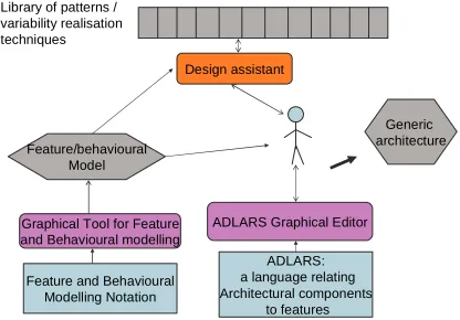
framework, for product line design. Verification (see e.g. Czarnecki [32]) will be an important function of the tools. Prototype graphical editors have been developed, both for the feature and behavioural modelling notation and for ADLARS. Feature and behavioural models, created using the graphical tool are saved in XML. They can be viewed within a browser with the aid of an XSL style sheet and can be imported into the ADLARS Graphical editor. This can then be used to create a generic software design with linkages back to features. Individual product feature sets can then be used to produce custom architecture descriptions for the products. However, because product features are linked to behaviour, the behaviour associated with architectural components can be identified, allowed the generation of code stubs by the ADLARS Editor. This capability has been demonstrated in the prototype tools and is currently being further developed.
ADLARS: a language relating Architectural components
to features ADLARS Graphical Editor
Feature and Behavioural Modelling Notation Graphical Tool for Feature and Behavioural modelling
Feature/behavioural Model
Design assistant Library of patterns /
variability realisation techniques
[image:8.595.325.533.327.472.2]Generic architecture
Fig. 5. Multiple tool Requirements modelling and design environment. ‘Design Assistant’ is an intelligent tool using Commonality/variability model information to actively support the identification of realisation techniques.
8. Conclusions and future work
language (a language relating the feature and architecture spaces), the behavioural information in the model can be carried across to the architecture design. Architectural Components therefore can have knowledge of the behaviour they must execute, thus opening the way for initial code generation.
Further work on understanding the relationships between variability points revealed within model fragment structures, and variability realisation techniques, is clearly needed and may lead to new notational concepts like those discussed above. Additionally, the introduction of explicit cardinality annotations, a contemporary concept that has emerged from the work of others, is currently under consideration.
One further point worth noting is that some work has been carried out [33] on the derivation of performance estimates from Use Case Maps, by first generating layered queuing networks (LQNs). This raises the possibility of a mechanism for assessing the performance costs associated with product features. In a product line context, the ability to make estimates of the performance implications associated with features and feature combinations would be a very useful capability. While we are not currently pursuing this issue, we are aware of the potential, another potential benefit of capturing feature behaviour in terms of the UCM notation.
9. Acknowledgements
We would like to thank the anonymous referees for their helpful comments on an earlier version of this paper.
10. References
[1] L. M. Northrop, “A Framework for Software Product-Line Practice – version 3”, Software Engineering Institute, 2001.
[2] Kyo C. Kang, G. C. Shalom, J. A. Hess, W. E. Novak and A. S. Petersen, “Feature-Oriented Domain Analysis (FODA) Feasibility Study”, Technical Report CMU/SEI 90-TR-21, 1990.
[3] M. Svahnberg, J van Gurp, and J. Bosch, “A Taxonomy of variability realization techniques”, Software-Practice and
Experience, vol. 35, 2005, pp. 705-754.
[4] J. van Gurp, J. Savolainen, “Service Grid Variability Realisation”, Proceedings of the 10th International Software Product line conference (SPLC2006), IEEE Computer Society Press, 2006, pp. 85-94.
[5] K. Lee, Kyo C. Kang, W. Chae and B.B. Choi, “Feature-based approach to object-oriented engineering of applications for reuse”, Software Practice and Experience, Vol. 30, 2000, pp. 1025 – 1046.
[6] Kyo C. Kang, S. Kim, J. Lee and K. Lee, “Feature-Oriented Engineering of PBX Software for Adaptability and Reusability”, Software Practice and Experience, vol. 29, 1999, pp. 875 – 896.
[7] M. Riebisch, K. Bollert, D. Streitferdt, and I. Philippow, “Extending feature diagrams with UML multiplicities”, 6th Conference on Integrated Design and Process Technology (IDPT), 2002,
[8] K. Czarnecki and C.H.P. Kim, “Cardinality-Based Feature Modeling and Constraints: A Progress Report”, OOPSLA’05
Workshop on Software Factories, 2005, available from
[9] K. Czarnecki, S. Helsen and U. Eisenecker, “Staged Configuration Through Specialization and Multi-Level Configuration of Feature Models”, Software Process Improvement and Practice, vol.10, no.2, 2005, pp.143-169.
[10] D. Fey, R. Fajta and A. Boros, “Feature Modeling: A Meta-model to Enhance Usability and Usefulness”,
Proceedings of the 2nd International Conference on Software
Product Lines (SPLC2), Springer, LNCS 2379, 2002, pp. 198
– 216.
[11] K. Czarnecki, T. Bednasch, P. Unger and U. W. Eisenecker, “Generative Programming for embedded software: An industrial experience report”, Proceedings of the
ACM SIGPLAN/SIGSOFT Conference on Generative
Programming and Component Engineering (GPCE’02),
Springer LNCS 2487, pp.156-172.
[12] T. Bednasch, “Konzept und Implementierung eines konfigurierbaren Metamodells fur die Merkmalmodel-lierung”, available (in german) from http:
[13] V. Chechticky, A. Pasetti, O. Rohlik and W. Schaufelberger, “XML-based feature modelling”, Proceedings of the 8th International Conference on Software Reuse: Methods, Techniques and Tools (ICSR 2004), Springer LNCS 3017, 2004, pp. 101-114.
[14] H. Mei, W. Zhang, F, Gu, “A Feature Oriented Approach to Modelling and Reusing Requirements of Software Product Lines”, Proceedings of the 27th International Computer Software and Applications Conference (COMPSAC’03). IEEE
Computer Society Press, 2003.
[15] M. Eriksson, J. Borstler, K. Borg, “The PLUSS Approach – Domain Modeling with Features, Use Cases and Use Case Realisations”, Proceedings of the 9th International Conference on Software Product Lines (SPLC 2005), Springer LNCS
3714, 2005.
[17] S. Hallsteinsen, T.E. Faegri and M. Syrstad, “Patterns in Product Family Architecture Design”, Proceedings of the 5th International Software Product Family Engineering Workshop (PFE 2003), Springer LNCS 3014, 2003, pp261-268.
[18] T. J. Brown, R. Gawley, R. Bashroush, I. Spence, P. Kilpatrick and C. Gillan, “Weaving Behavior into Feature Models for Embedded System Families”, Proceedings of the 10th International Software Product line conference (SPLC2006), IEEE Computer Society Press, 2006, pp. 52-61.
[19] R.J.A. Buhr, R.S. Castleman, “Use Case Maps for Object
Oriented Systems”, Prentice Hall, 1996.
[20] R.J.A. Buhr, “Use Case Maps as Architectural Entities for Complex Systems”, IEEE Transactions on Software
Engineering, Dec. 1998, pp 1131 - 1155.
[21] D. Amyot, “Use Case Maps as a Feature Description Language”, Proceedings of FireWORKS ’00, S. Gilmore and M. Ryan (Eds), Language Constructs for Designing Features. Springer-Verlag, 2000, pp. 27 - 44.
[22] ITU-T URN Focus Group (2002) Draft Rec. Z152 – UCM: “Use Case Map Notation (UCM)”, ITU_T, Geneva, 2002.
[23] UCM web site at : http://www.usecasemaps.org.
[24] T.J. Brown, I. Spence and P. Kilpatrick, “A Relational Architecture Description Language for Product Families”, Proceedings of the 5th International Software Product Family Engineering Workshop (PFE 2003), Springer LNCS 3014, 2003, pp282-295.
[25] T.J.Brown, R. Bashroush, I.Spence, P.Kilpatrick, “Feature Guided Architecture Development for Embedded System Families”, Proceedings of the IEEE Working
International Conference on Software Architecture, (WICSA),
2005.
[26] K. Czarnecki and U. W. Eisenecker, “Generative
Programming: Methods Tools and Applications, - Chapter 4”,
Addison-Wesley, 2000.
[27] M. de Jonge and J. Vissor, “Grammars as feature Diagrams”, in ICRS7 Workshop on Generative Programming (GP2002), online proceedings available at
http://www.cwi.nl/events/2002/GP2002/
2002.html, pp. 23-24.
[28] D. Batory, “Feature Models, Grammars and Propositional Formulae”, Proceedings of the 9th Software Product line Conference (SPLC 2005), 2005, Springer LNCS 3714.
[29] K. Czarnecki, S. Helsen andU. Eisenecker, “Formalising Cardinality-based Feature Models and their Specialisation”, Software Process Improvement and Practice, vol. 10, no. 1, 2005, pp. 7 – 29.
[30] H. H. Vogt, S. D. Swierstra and M. F. Kuiper, “Higher Order Attribute Grammars”, Proceedings of the ACM
SIGPLAN Conference on Programming Language Design and Implementation, 1989, pp. 131-145.
[31] ITU-T Recommendation G.664, “Optical safety
procedures and requirements for optical transmission systems”, International Telecommunication Union, 2003.
[32] K. Czarnecki and K. Pietroszek, “Verifying feature-based model templates against well-formedness OCL constraints”,
Proceedings of the 5th international Conference on Generative Programming and Component Engineering
(Portland, Oregon, USA, October 22 - 26, 2006). GPCE '06. ACM Press, New York, NY, pp211-220.
[33] D. Petriu and M. Woodside, “Software Performance Models from System Scenarios in Use Case Maps”,
Proceedings of the 12th International Conference on
Modelling Techniques and Tools, (TOOLS 2002), 2002,