http://www.scirp.org/journal/jamp ISSN Online: 2327-4379
ISSN Print: 2327-4352
Simulation of Radiant Heat Transfer on the
Border of Coke Bed and Metal Surface of
Heat Transfer Passage
L. D. Zabezhinskiy
Eastern Coal-Chemical institute (VUHIN), Ekaterinburg, Russia
Abstract
The article is dedicated to the issues of heat transfer, radiant heat transfer in particular, between fluidized bed of coke and water-cooled panels arranged inside it in a staggered order. The model by A.F. Chudnovsky describing ra-diant heat transfer in a porous body (disperse medium) as applied to coke bed has been updated.
Keywords
Coke Cooling, Heat Transfer Coefficient, Angular Radiation Coefficient, Pore Body Model, Water-Cooling Panel, Heat Tubes
1. Introduction
Earlier publications by the author give a description of an energy technological boiler (ETB) for cooling coke and thermal preparation of coal blend in which
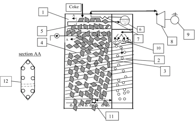
use is made of heat tubes (Figure 1) for cooling coke at the expense of solid
heat-carrier and heat transfer from hot coke to coal blend. ETB is key unit of improved technology “combine process of coal blend thermal preparing and coke dry cooling”. This technology initially has been offered by B.I. Babanin and V.I. Babanin in 1980 and proposed heat transfer from cooling coke to warmed coal blend in drum heat changer. This technology has one defect: coke obstruc-tion by coal dust because of heat transfer of two discrete environments by means of mix. With purpose to avoid this defect author in common with E.I. Dorman proposed to carry out heat transfer between coke and coal blend by means of heat tubes (closed two-phase thermosiphons) [1].
2. Construction ETB and Model Description
The ETB design is described in detail in [2], detailed investigation of heat trans-
How to cite this paper: Zabezhinskiy, L.D. (2017) Simulation of Radiant Heat Transfer on the Border of Coke Bed and Metal Sur-face of Heat Transfer Passage. Journal of Applied Mathematics and Physics, 5, 83-91. http://dx.doi.org/10.4236/jamp.2017.51009
Received: October 17, 2016 Accepted: January 21, 2017 Published: January 24, 2017
Copyright © 2017 by author and Scientific Research Publishing Inc. This work is licensed under the Creative Commons Attribution International License (CC BY 4.0).
L. D. Zabezhinskiy
Figure 1. Schema ETB. 1—coke cooling chamber; 2—coal blend heating chamber; 3— partition; 4—heat tubes (tube panels in cooling chamber); 5—flow heat changer; 6—boi- ler drum; 7—steam-heater; 8—steam turbine; 9—turbogenerator; 10—coal blend; 11— coke pusher of discharge device.
fer [3], both in coke cooling and in coal blend heating chambers, was generalized
in [4]. ETB schematic construction has shown on Figure 1. Heat transfer in a
coke cooling chamber between coke bed and water panels with heat tubes inside was studied both experimentally and theoretically, while for the case of a coal blend heating chamber, the study was only theoretical. The issue of the heat transfer level is of paramount importance, since it benchmarks ETB efficiency as a heat changer, and its dimensions, particularly in an ETB integrated with an operating coke-oven battery, which may impose restrictions on a built-in unit.
Considered in the present publication is heat transfer in the coke cooling process as a factor defining the ETB vertical dimensions. The coal blend heating chamber provides an opportunity to intensify heat exchange, in particular at the expense of counter-flow of cold (280˚C) coke-oven gas present in the flue of a coke-oven battery. This method was patented by the author in co-authorship
with V.M. Ljapunov [5]. However use of the same gas in a coke cooling chamber
is problematic, first, because of the impermeable solid bed used in this camera, secondly, because of potential ability of such gas being taken aside from the chamber top part to exert negative influence on the quality of coke leaving the ETB, and thirdly, due to danger of deteriorating the environment near the ETB. The presence of high CO concentration in the atmosphere in the vicinity of the USTK (Coke Dry Cooling Plant) utilizing coke-oven gas was proved.
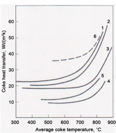
Initial findings on coke heat transfer coefficients at its contact with water- cooled panels were made in an experiment conducted with the participation of the author in a pilot plant at the Krivorozhsky Coking Plant [6]. The heat trans-fer coefficient values after the experiment in [6] are shown in plots of αc = f t
(
coke)
in Figure 2.
Figure 2. Coke heat transfer dependence on average coke temperature and on coke scrap size. 1 - 6—different blends numbers; - - -moving bed, —immovable bed.
technical project with a plan to utilize a flowing heat changer for heating water and generating superheated steam in a combined process. The technical project has developed by the Belgorodenergomash Company in 1993. According to this variant, heat transfer to coal blend was ensured by mixing coke and coal blend in a drum-type heat changer.
3. Research Method
The parabolic nature of experimental curves in Figure 2 testifies to the radiant component making a decisive contribution to total heat exchange. According to
A.F. Chudnovsky’s model [7] of heat transfer in a porous solid, the radiant
component must be proportional to 3
c T :
2 3
.eff 2 eff ,
c d Tc
λ = ε σ (1)
where λc.eff is effective coefficient of heat conductivity, radiant heat transfer for
the most part, in a disperse medium bed;
ε is bed particles emissivity factor (blackness degree);
σ is Stefan-Boltzmann constant;
c
T is average coke bed absolute temperature, ˚К;
eff
d is effective particle size;
2 = φ—is total angular radiation coefficient of a prismatic pore computed by Chudnovsky for his interlump void model presented in the form of an oblong parallelepiped.
L. D. Zabezhinskiy
2 3
.eff .eff eff 2
c c d f T
α = λ = ε σ (2)
where αc.eff is effective coefficient of coke heat transfer.
In Krivorozhsky pilot plant a coke piece (scrab) effective size was deff = 55 mm. In further profound analysis of simulation environment of heat transfer in a pilot plant it was established that the ETB heat-exchange element model imple-mented in the pilot plant at the Krivorozhsky Coking Plant was slightly different from the designed (full-scale) heat changer in shape of the surface exposed to radiant heat flow: that of the panels with heat tubes and flowing heat changer tubes. Panel surface of full-scale heat changer makes by polished steel sheet (see section AA, Figure 1).
In the pilot plant model, the panel surface is formed of channel bars welded in row, with welding joints interrupting the heat exchange receiving surface, and so, instead of a continuous sheet (in full-scale variant) there is present a row of rela-tively narrow plates (see below, Figure 4). Reference-books on radiant heat ex-change give essentially different values for angular radiation coefficient φ pre- sent in the radiant heat exchange formula:
3 .eff 1 2 1
c T
α =ϕε ε σ (3)
where φ angular radiation coefficient;
1 2 ,
ε ε —blackness degree of coke and steel sheet.
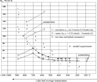
The results of αc.eff calculations by formula (2) are shown in Figure 3 (curve
1). Curve 4 in the same figure shows the experimental values of αc.eff
accord-ing to studies [4]. The divergence of curves 1 and 4 at up to t = 920˚C is as large as 45% of the greatest (calculated) value of αc.eff according to Formula (3),
however becoming to zero at 400˚C.
Let us consider the causes of this divergence. The main cause is the following.
In Formula (1) the value emissivity factor ε are assumed to be equal for two
opposite planes of a pore, since the formula has been derived for a closed pore inside bed. However, for an open pore located at bed edge, ε2should be
substi-tuted for the product of ε ε1 2, where ε1 is coke emissivity factor, and ε2 is panel
material emissivity factor.
For polished steel sheet in the temperature range of t=500 - 900C, the
ref-erence-book gives the value of ε =2 0.50 - 0.53, and for coke, ε =1 0.80 - 0.86.
Thus the product of values ε ε =1 2 0.43, instead of
2 1 0.69
ε = according to
Chudnovsky’s canonical formula, which is 1.6 times less. Plot αc.calc (τ) recalcu-lated with account for this relation is shown on curve 2 (Figure 3). It is consi-derably closer here to the experimental values (curve 4, see Figure 3).
Let us consider further, in accordance with Chudnovsky’s model [7],
coeffi-cient 2 in Formulas (2) and (3) as a sum of angular coefficoeffi-cients of radiation φ from five planes of pore, including bottom, onto the sixth plane located opposite to the bottom. For internal pore in Chudnovsky’s model, it is
(
0)
(
)
4 4 4 0.2 4 0.075 2
ϕ= ϕ + ψ = + ⋅ = (4)
where ϕ0—angular coefficient of radiation from bottom of pore to 6-th plane;
Figure 3. Graphs of calculated and experimental values αc,eff.
Let us consider ϕ as angular coefficient of radiation from bottom, with
tak-ing into account mutually disposition and sizes of two parallel planes: pore bot-tom (coke) and steel panel wall (Figure 4 and Figure 5). In our case of coke-to- metal heat exchange, coefficient ϕ0 should be slightly increased following the
considerations below.
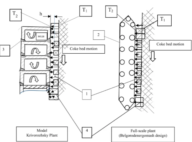
In consideration of our case, in passing to the outer (near-wall) row of coke particles, let us note also that the interlump pore becomes open from the side of the parallelepiped sixth plane, which is the surface of the water-cooled panel. Here small gap h may appear between coke and the panel due to coke particles scuffing on panel surface, mainly on coating sheet welding joins (see Figure 4).
Radiation from bottom of an open pore prevails among other kinds of heat
exchange between coke and panel, first, due to bottom high temperature Т1
which is approximately 100˚C - 200˚C higher than temperature Т2 of the ridge
contacting the water-cooled panel (see Figure 2, and calculations in [4]), and secondly, due to a smaller surface exposed to other types of heat transfer (con-tact heat transfer-point heat transfer; convective heat transfer in the high-tem- perature part is practically absent due to small gaps).
In the reference-book [8], for two parallel long-length plates (of a full-scale, or industrial, heat changer), there is given the value of angular radiation coefficient φ12 = 0.6, while the classical work by R. Ziegel and G. Howell [9] gives the value of φ12 = 0.42 for similar surfaces. We take the average value of φ12,full-sc = 0.51.
L. D. Zabezhinskiy
Figure 4. Radiant heat transfer coke-panel model. 1—near-wall coke bed; 3—welding joint; 4—radiant heat transfer coke-panel.
[image:6.595.211.537.64.305.2](a) (b) (c)
Figure 5. Detail models of radiation in pores. (а) Model of closed pore according Chud-novsky; (b) Model of open pore in Krivorozhsky pilot plant; (c) Model of open pore in full-scale plant.
for different sizes of rectangular strips from 0.2 to 0.5 [8], i.e., on the average, φ12 = 0.35. This coefficient corresponds to the physical model geometry in the pilot plant experiment. Then the full-scale/model ratio of angular radiation coeffi-cients for bottom ϕ12нат ϕ12мод =0.51 0.35=1.457.
Coefficient φ0 in formula (3) will be equal to ϕ =0 0.2 1.457⋅ =0.291. By
subs-tituting this value in Formula (4), we obtain the total (integral) angular radiation coefficient ϕ =4 0.291 4 0.075
(
+ ⋅)
=2.364, instead of 2.0, i.e., φ increases by18% (assuming that the for porous surface angular radiation coefficients ψ of
the pore side planes remain unchanged). Proportionally with φ, heat transfer coefficient αc.eff (average for all stages) also increases by 18%. This is the primary factor of heat transfer coefficient increase in final calculations as compared with that in publication [10].
4. Research Outcome
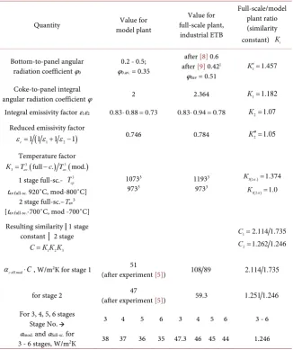
[image:6.595.260.485.354.455.2]resulting similarity constants heat transfer coefficients for all heat changer stag-es, are given in Table 1.
With new input data, emissivity factor 2
2 1 2 1.07
К =ε ε ε = ; and, according
to the known formula, with same areas of parallel surfaces radiating upon one another, the reduced emissivity factor is: εп=1 1
(
ε1+1ε2− =1)
0.746 formodel and 0.784 for full-scale plant. Similarity constant К2′′ =εfull scale− εmodel 1.05= ,
which closely approximates К2.
The temperature factor for first stage
(
)
33 full scale mod 1.374
К = Т − Т = (see
Ta-ble 1). Thus, the value of αc.eff included in the heat transfer equation increases 2.11 times in the heat changer first stage and 1.25 times in the second and sub-sequent stages, as compared with the values adopted in the industrial heat
ex-changer thermal design [10]. Heat balance calculations accounting for new
[image:7.595.213.540.328.718.2]val-ues of heat transfer coefficients allow reduction by 1 to 2 of the number of heat transfer stages, i.e., by 2.5 to 5 meters in height, and reduction by 15% - 25% of the specific amount of metal per ETB.
Table 1. Calculated heat transfer coefficients for model and full-scale plants.
Quantity model plant Value for
Value for full-scale plant, industrial ETB Full-scale/model plant ratio (similarity constant) Кi
Bottom-to-panel angular radiation coefficient φ0
0.2 - 0.5; φ0.av. = 0.35
after [8] 0.6 after [9] 0.42}
φ0av = 0.51
1 1.457 К′ =
Coke-to-panel integral
angular radiation coefficient φ 2 2.364 К1=1.182
Integral emissivity factor ε1ε2 0.83 0.88⋅ =0.73 0.83 0.94⋅ =0.78 К2=1.07 Reduced emissivity factor
( 1 2 )
1 1 1 1
r
ε = ε + ε − 0.746 0.784 К2′′ =1.05
Temperature factor
( ) ( )
3 3
3 av. full . av. mod.
К =T −c T
1 stage full-sc.- 3
cp
T tav.full-sc. 920˚C, mod-800˚C]
2 stage full-sc.–Tav3
[tav.full-sc.-700˚C, mod -700˚C]
10733
9733 1193
3
9733
( ) 3 1 .st 1.374
К =
( ) 3 2st 1.0
К =
Resulting similarity | 1 stage constant │ 2 stage
1 2 3 С К К К=
1 2.114 1.735
С =
2 1.262 1.246 С =
.eff mod
c C
α ⋅ , W/m2К for stage 1 51
(after experiment [5]) 108 89 2.114 1.735
for stage 2 47
(after experiment [5]) 59.3 1.251 1.246 For 3, 4, 5, 6 stages
Stage No. → 3 4 5 6 3 4 5 6 3 - 6
αmod. and αfull-sc. for
3 - 6 stages, W/m2К 38 37 36 35 47.3 46 45 44 1.246
L. D. Zabezhinskiy
The total heat flux, as per the above outlay, is equal to
(
)
3(
)
eff 1 2
c c w c w
Q=a F T −T =ϕε ε σT F T −T (5)
where F is effective area of coke radiating surface;
(
Tc−Tw)
is temperature gradient between the outer (near-wall) row of coalpieces and the water-cooled panel wall. For other designations see above.
By substituting the average values of coefficients included in Formula (5), we obtain the ETB stage 1 thermal consumption of 17.4 MW which, at steam tur-bine plant and turbo-generator efficiency of about 30%, converts to the ETB stage 1 electrical output of ~5.2 MW, with the aggregate stage 1 and stage 2 elec-trical output of about 7.2 MW. Thus the energy saving is also a feature of the given technology, that essentially increase its economic efficiency.
5. Discussion
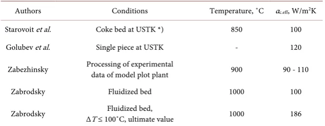
Into conclusion, we compare our results with other author’s experimental data (Table 2).
As it can see, results of comparison with experiments by other authors are quite satisfactory.
6. Conclusions
1) Heat engineering calculations (inclusive heat balance) show that building of ETB is possible, and ETB highly effective as a heat changer. All calculations car-ried out using in our researching received heat transfer coefficients. There is represented comparison with Russian, Ukrainian and German author’s data about heat transfer coefficients of coke.
2) Besides coke making advantages there is profit at energy saving: attached to ETB, steam turbine plant can generate electric power about 5 - 7 MW by coke battery productivity 100 t/h.
3) Ecologic advantages of this technology are combining process of coal blend thermal preparation and coke cooling in one hermetic corpus, issued from a
[image:8.595.209.541.590.719.2]minimum number of overloads [3].
Table 2. Comparison of αc.eff with other author’s data.
Authors Conditions Temperature, ˚C αc.eff, W/m2K
Starovoit et al. Coke bed at USTK *) 850 100
Golubev et al. Single piece at USTK - 120
Zabezhinsky Processing of experimental
data of model plot plant 900 90 - 110
Zabrodsky Fluidized bed 1000 100
Zabrodsky ∆T ≤ 100˚C, ultimate value Fluidized bed, 1000 186
4) Economic evaluations show [3] that full compensation of capital expendi-tures will be expected for 5.5 years after investment begins or 3 - 5 months from plant starting on full power.
References
[1] Zabezhinskiy, L.D., Dorman, E.I., et al. (2005) Energy-Technologic Plant for Cоke Cooling and Coal Blend Thermal Preparing. Patent of RF No. 2035489.
[2] Zabezhinskiy, L.D. (2013) On the Prospects of Introduction in Russia Energy- and Resourcesaving Technology of Coal Blend Thermal Preparing and Cоke Radiation Cooling. Coke and Chemistry, No. 11, 51-59.
[3] Zabezhinskiy, L.D. (2015) Heat Transfer in the Energy-Technological Boiler with Heat Tubes Intended for Coal Blend Thermal Preparing and Coke Radiation Cool-ing. Coke and Chemistry, No. 8, 37-45.
[4] Zabezhinskiy, L.D. (2016) Coal Blend Thermal Preparing and Coke Cooling. “Lap Lambert” Academic Publishing, Saarbrucken, 80 p.
[5] Zabezhinskiy, L.D. and Ljapunov, V.M. (2016) Energy-Technological Plant for Coke Cooling and Coal Blend Thermal Preparing. Patents RF No. 2596759, 25967606. [6] Staheev, S.G., Zabezhinskiy, L.D. and Ljahov, Ju.N. (1992) Research in Field of
Ela-boration Energy-Technological Unit for Combine Process Coal Blend Thermal Preparing and Coke Cooling. Coke and Chemistry, No. 2, 34-38.
[7] Chudnovsky, A.F. (1962) Termophysic Characteristics of Dispersive Materials. Phys-Matgiz, Moscow, 456 p.
[8] Bloh, A.G., Zhuravlev, Ju.A. and Rizhcov, L.N. (1991) Radiation Heat Transfer. Reference Book. Energoatomizdat, Moscow, 432 p.
[9] Ziegel, R. and Howel, D. (1975) Radiation Heat Transfer. Peace, Moscow.
[10] Zabezhinskiy, L.D., Prohorova, M.F., Prohorov, V.V., Milshtein, M.N. and Staheev, S.G. (1997) Decision of Conjugated Problem of Heat Transfer in Energy-Technolo- gical Boiler with Movable Dispersive Material. Journal of Engineering Physics and Thermophysics, 70, 748-752.
Submit or recommend next manuscript to SCIRP and we will provide best service for you:
Accepting pre-submission inquiries through Email, Facebook, LinkedIn, Twitter, etc. A wide selection of journals (inclusive of 9 subjects, more than 200 journals)
Providing 24-hour high-quality service User-friendly online submission system Fair and swift peer-review system
Efficient typesetting and proofreading procedure
Display of the result of downloads and visits, as well as the number of cited articles Maximum dissemination of your research work
Submit your manuscript at: http://papersubmission.scirp.org/