MPLS Traffic Engineering in ISP Network
Mohsin Khan
Birmingham City University, England
ABSTRACT
Multi Protocol Label Switching (MPLS) is an innovative and vibrant technology. The most famous applications of MPLS technology are MPLS VPN, MPLT Traffic engineering and MPLS QoS and Any Transport over MPLS (AToM).
This
study addressed only MPLS Traffic engineering, which is one of the driving factors of deploying MPLS in service provider networks. This research consists of two main sections; in the first section basic concepts of MPLS have been reviewed and in the second section, implementation of the MPLS based ISP network, configuration and verification of the results are covered. Simulation results show that on large service provider networks, no other technology can engineer traffic as efficiently as MPLS does. This research aims to provide guidelines for network engineers for efficiently engineering network traffic in the service provider network.Keywords: MPLS, RSVP, CBTS, CSPF, Fast reroute.
1.
IINTRODUCTION
The modern networks are converged networks; they carry voice, video and normal data by using the same network resources. Since some user data traffics such as voice, video or SQL bank transactions are more important and less tolerant to delay; they are preferentially treated based on their delivery requirements such as bandwidth and maximum affordable delay [1]. Considering the increased number of internet users and different network data traffic types, internet service providers (ISP) face a challenge in the form of Traffic Engineering.
MPLS Traffic Engineering [2] is one of the most exciting and powerful applications of MPLS which provides network optimization by flexibly utilizing all the available links in the network. MPLS provide an integrated approach to divert network traffic from congested parts of the network to non-congested parts [3]. In traditional IP networks [4], Links under-utilization was a big problem where one (best) route was over used for heavy network traffic and the other routes were unused or less used. Thus bandwidth was wasted. To address the problem of link under-utilization, one solution is to force load balancing [16] on the links by using routing protocols. In this method we change the metric of the link and this may potentially change the path of all the packets traversing the link [1]. This solution is not scalable in large service provider networks where it is very hard to manage load balancing on hundreds of routers. The most efficient and better way to utilize all the available links in the network is MPLS Traffic Engineering. By using MPLS TE we can very conveniently utilize the available network resources to their optimal potential [18]. MPLS TE lets us to engineer the traffic the way we wants not the way routing protocol wants. It was not possible with traditional IP networks. Traditional IP network forwards all the traffic on the shortest path calculated by SPF algorithm [5]; it doesn’t consider non-shortest paths for traffic sending regardless the
[image:1.595.310.526.234.425.2]fact that they may be enough bandwidth links. MPLS TE lets us create LSP tunnels on the non-shortest paths that satisfy the bandwidth requirements, and then we map traffic to these LSP tunnels to avail the bandwidth.
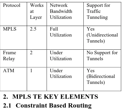
Table 1: Comparison of MPLS with Frame Relay and ATM
Protocol Works at Layer Network Bandwidth Utilization Support for Traffic Tunneling MPLS 2.5 Full
Utilization Yes (Unidirectional Tunnels) Frame Relay
2 Under
Utilization
No Support for Tunnels
ATM 1 Under
Utilization
Yes
(Bidirectional Tunnels)
2.
MPLS TE KEY ELEMENTS
2.1
Constraint Based Routing
In constraint based routing a shortest path is selected if it satisfies a particular set of constraints. The constraints are minimum bandwidth, link attributes and administrative weight, setup and hold priority values etc. [2] MPLS TE uses constraint shortest path first algorithm (CSPF) to build LSP tunnels. CSPF is an extension of SPF [6] and it looks not only on the cost values but also on the constraints to select the best path according to the resource requirements.
2.2
RSVP Signaling
RSVP [7] is a resource reservation protocol; it allocates bandwidth along the LSP for tunnels to establish. RSVP messages are sent by headend router for resource reservations. A headend router is the starting point of the tunnel whereas tailend is the ending point of it [8]. The actual available bandwidth is configured on the physical interfaces, which is announced by RSVP. The desired bandwidth for the establishment of tunnels is configured on the tunnel interfaces. So before establishing a tunnel desired bandwidth of the tunnel and the available bandwidth announced by RSVP are compared. If there is enough bandwidth available to accommodate the tunnel, the tunnel will establish along the LSP.
2.3
Class Based Tunnel Selection
particular tunnel if the CoS of the traffic matches the value configured on tunnel. There are only three 3 bits specified in EXP field of MPLS label which are used for QoS purposes [10]. Therefore there can be a maximum of 8 different tunnels between same head end and tail end devices.
2.4
Fast Reroute
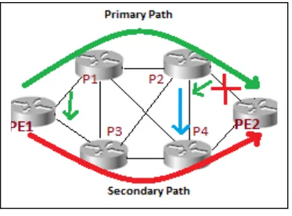
Fast Reroute (FRR) [11] is very important factor of MPLS TE. If a link or a node fails in LSP of MPLS network, FRR automatically reroutes traffic [11] i.e. switches traffic to the secondary path. For FRR, there are two paths; Primary path and Secondary or Backup path [17]. Primary path is the main tunnel used to carry traffic. Secondary path is used to carry traffic if a node or a link fails in primary tunnel. FRR reduces the packet loss and restores the tunnel electric fast [12]. The purpose of FRR is to reduce the packet loss and reroute the traffic as soon as possible. Though routing algorithm such is SPF algorithm can also recalculate new paths after the occurrence of a node or a link failure but this process is slow. It takes time for routing protocols to propagate link or node failure information across the network. Important traffic such as voice and video can’t wait for longer. They need a good QoS if not to drop packets.FRR provides protection against two types of failures [13].
1) Link Failure 2) Node Failure
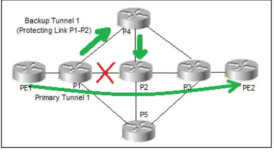
Rerouting of traffic after link failure is illustrated in the figure 1(a).
Figure 1(a): FRR with Link Protection
If link between P2 and PE2 fails somehow, P2 will quickly switch the traffic to the P4 through detour i.e. through PE1->P1->>P4->PE2. P2 will also signal PE1 about link P2-PE2 failure. As soon as PE1 knows about link P2-P2-PE2 link
failure, it diverts traffic to secondary tunnel i.e. to PE1->P3->P4->PE2.
Figure 1(b) shows the rerouting of traffic after a node failure
Figure 1(b): FRR with Node Protection
When node P2 fails, P1 quickly switches traffic to P4 through detour path which is PE1->P1->P4->PE2. P2 make a notice of node P2 failure to head end router i.e. PE1 and traffic is then diverted to secondary path which is PE1->P3->P4->PE2.
3.
NETWORK IMPLEMENTATION
3.1
Primary Tunnels Implementation
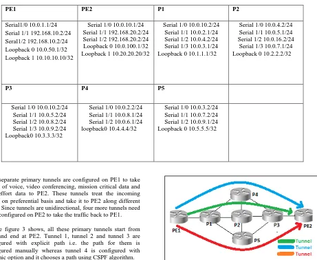
[image:2.595.314.530.120.252.2]We used dynagen simulator to create an MPLS based ISP network used in this research work. Figure 2 shows the logical topology of the ISP network which we used to work on MPLS TE and fast rerouting.
Figure 2: Topology of MPLS based ISP Network
[image:2.595.59.270.390.546.2] [image:2.595.313.538.417.504.2]Table 2: IP addressing scheme on ISP network
PE1 PE2 P1 P2
Serial1/0 10.0.1.1/24 Serial 1/1 192.168.10.2/24 Seral1/2 192.168.10.2/24 Loopback 0 10.0.50.1/32 Loopback 1 10.10.10.10/32
Serial 1/0 10.0.10.1/24 Serial 1/1 192.168.20.2/24 Serial 1/2 192.168.20.2/24 Loopback 0 10.0.100.1/32 Loopback 1 10.20.20.20/32
Serial 1/0 10.0.10.2/24 Serial 1/1 10.0.2.1/24 Serial 1/2 10.0.4.2/24 Serial 1/3 10.0.3.1/24 Loopback 0 10.1.1.1/32
Serial 1/0 10.0.4.2/24 Serial 1/1 10.0.5.1/24 Serial 1/2 10.0.16.2/24
Serial 1/3 10.0.7.1/24 Loopback 0 10.2.2.2/32
P3 P4 P5
Serial 1/0 10.0.10.2/24 Serial 1/1 10.0.5.2/24 Serial 1/2 10.0.8.2/24 Serial 1/3 10.0.9.2/24 Loopback0 10.3.3.3/32
Serial 1/0 10.0.2.2/24 Serial 1/1 10.0.8.1/24 Serial 1/2 10.0.6.1/24 loopback0 10.4.4.4/32
Serial 1/0 10.0.3.2/24 Serial 1/1 10.0.7.2/24 Serial 1/2 10.0.9.1/24 Loopback 0 10.5.5.5/32
Four separate primary tunnels are configured on PE1 to take traffic of voice, video conferencing, mission critical data and best effort data to PE2. These tunnels treat the incoming traffic on preferential basis and take it to PE2 along different LSPs. Since tunnels are unidirectional, four more tunnels need to be configured on PE2 to take the traffic back to PE1. As the figure 3 shows, all these primary tunnels start from PE1 and end at PE2. Tunnel 1, tunnel 2 and tunnel 3 are configured with explicit path i.e. the path for them is configured manually whereas tunnel 4 is configured with dynamic option and it chooses a path using CSPF algorithm.
[image:3.595.49.522.515.649.2]Figure 3: Tunnels with explicit path from PE1 to PE2
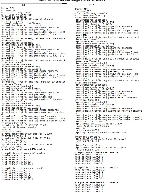
Table 3: primary tunnels configured in the MPLS backbone network running from PE1 to PE2
PE1 Destination Tunnel EXP Setup-Hold priority Path option
Master tunnel 10
10.0.100.1 (PE 2)
Tunnel 1 (voice) 5 3-3 explicit
Tunnel 2 (video conferencing) 4 4-4 explicit
Tunnel 3 (critical Data) 3,2 5-5 explicit
Tunnel 4 (best Effort) - 6-6 dynamic
3.2
Tunnel 1
Tunnel 1 is created to take voice traffic from PE1 to PE2. It is created along the path PE1>P1>P2>P3>PE2. Since voice data can’t afford much delay or jitter, we have allocated sufficient bandwidth to tunnel 1 to avoid any delay for voice. EXP value 5 instructs Tunnel 1 to look for the incoming traffic with EXP value 5 to accept. The traffic with EXP value other than 5 is not accepted by the tunnel 1. So using this value tunnel 1 will take only voice data. Setup priority and hold priority [14] are two important values. They simply tell how important the
dynamically or explicitly. Dynamic option makes use of CSPF to calculate best path for the tunnel. Explicit option doesn’t use CSPF to choose the path for the tunnel; instead we manually configure the path to be taken by tunnel. We configure a hop-by-hop path to the tail end. Only tunnel 4 in our network is configured with dynamic path option.
3.3
Tunnel 2
Tunnel 2 is created to carry video conferencing data from PE1 to PE2. It is explicitly established along the LSP PE1>P1>P4>P3>PE2. Tunnel 2 looks for EXP value of 4 in the MPLS label to take traffic of video conferencing. Its setup and priority values are 4-4, so it can pre-empt all the tunnels in the network except tunnel 1 and it can’t be pre-empted by any tunnel except tunnel 1.
3.4
Tunnel 3
It carries traffic mission critical data such as important SQL bank transactions. It is also explicitly configured and it is established on the LSP PE1>P1>P5>P3>PE2. Tunnel 3 takes traffic only with EXP value of 3 and 2 in its label. It can pre-empt only tunnel 4 in the network and it can be pre-pre-empted by tunnel 1 and 2 because they are more important than tunnel 3 and they carry important voice and video conferencing data.
3.5
Tunnel 4
Tunnel 4 is best effort tunnel. It takes normal data. It is configured with dynamic option so it can take any LSP to carry data from PE1 to PE2. No path is explicitly configured for it. It can’t pre-empt any of the tunnels in the network, and it can be pre-empted by any of them because their setup and hold priority values are lower than tunnel 4. Since no path is explicitly configured for dynamic tunnel 4, no FRR mechanism can be configured for it.
3.6
Master Tunnel 10
Master tunnel [15] contains a group of tunnels having the same head ends and tail ends. Since all 4 tunnels in our network heads from PE1 and ends at PE2, we group them in master tunnel 10.
3.7
Fast Reroute Implementation
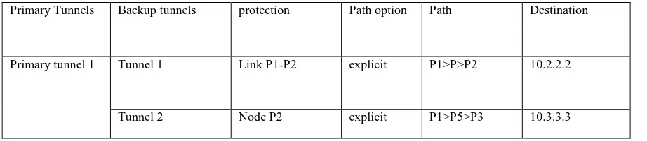
[image:4.595.47.508.339.440.2]Two backup tunnels are configured on primary tunnel 1 for link and node protection as shown in the table 3.
Table 4: Backup tunnels on P1 to protect primary tunnel 1
Primary Tunnels Backup tunnels protection Path option Path Destination
Primary tunnel 1 Tunnel 1 Link P1-P2 explicit P1>P>P2 10.2.2.2
Tunnel 2 Node P2 explicit P1>P5>P3 10.3.3.3
3.8
Backup Tunnel 1
This tunnel is configured on P1 along primary tunnel 1 to provide protection at link between P1 and P2. It is explicitly configured along the path P1>P4>P2. It starts from P1 and ends at P2. In case of link P1-P2 failure, It will divert traffic to LSP P1>P4>P2.
3.9
Backup Tunnel 2
This tunnel is also configured on P1 and provides protection against node P2 failure along primary tunnel
1. In case of failure of node P2, backup tunnel 2 will skip node P2 and divert traffic to LSP P1>P5>P3.
RSVP sends hello messages to the neighbor routers to check the link or node failure. RSVP checks node-to-node failure detection, if a node doesn’t receive acknowledgment from its neighbor node for a given number of times, it announces it down and hence the primary tunnel is announced down. Now the interfaces facing the protected link or node must have to be configured to switch the traffic to backup tunnels in case of link or node failure along the primary tunnels.
4.
CONFIGURATION OF MPLS TE &
FRR
5.
EXPERIMENT RESULTS
5.1
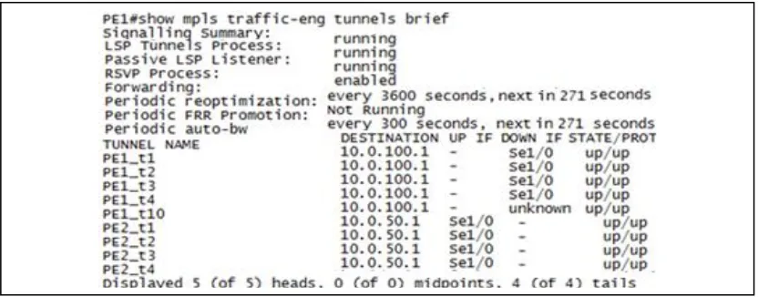
Verification of Primary Tunnels
The results obtained from the implemented network verify that 4 primary tunnels are successfully created to take voice,
[image:7.595.55.460.92.491.2]video conferencing and mission critical data on preferential basis and to avoid delay which could distort data traffic.
Figure 4: Primary Tunnels on MPLS ISP Network
Figure 4 shows all the primary tunnels configured in the network are up. The top 5 tunnels are configured on PE1, and are destined to PE2. So PE1 serves as the headend and PE2 as
[image:7.595.54.470.534.697.2]Figure 5: Master tunnel 10
[image:8.595.314.548.103.182.2]Tunnel 10 is the master tunnel configured on PE1. It consists of 4 primary tunnels. Since destination is 10.0.100.1 (PE2), all these four tunnels start at PE1 and end at PE2. Tunnel 1 contains EXP value of 5, which means that it will carry voice data. Tunnel 2 has an EXP value of 4, so it will carry video data, tunnel 3 will carry critical data such as important bank transactions because it has EXP values of 2 and 3. Tunnel 4 will carry best effort data since it doesn’t have any EXP value. Tunnel 4 makes use of CSPF algorithm for its establishment. Tunnel 4 can be established on any LSP in the network as indicated by CSPF algorithm.
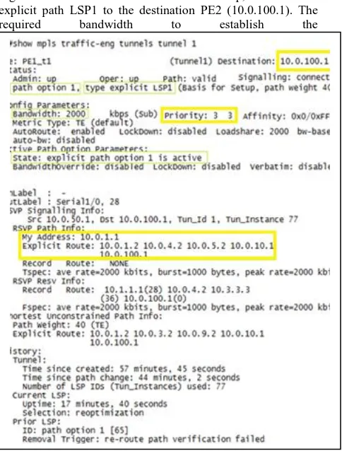
Figure 6 shows that the status of tunnel 1 is up, it follows the explicit path LSP1 to the destination PE2 (10.0.100.1). The required bandwidth to establish the
Figure 6: Primary tunnel 1 with full details
Tunnel is 2000 kb/s and the setup and hold priority values are set to 3. The explicit path to be followed by the tunnel 1 is also given.
RSVP signaling is another pivotal feature of MPLS TE. It signals to reserve the bandwidth for the MPLS tunnels to
establish to carry data traffic of different CoS. The following figure shows the details of the RSVP sender.
Figure 7: RSVP signals sent by PE routers
Figure 7 shows the RSVP signals sent by PE1 to PE2 and also from PE2 to PE1. Since 4 primary tunnels have been configured on PE1, it sends 4 RSVP signals to PE2. The first three tunnels requested a bandwidth of 2000kb and the fourth tunnel, which carries best effort traffic, requested only 100kb. Pro, DPort and SPort denotes Protocol code, Destination port and Source port. Prev Hop field shows t
The previous hop and I/F field shows the interface connecting to the previous hop. Similarly PE2 also sent 4 RSVP signals to PE1 and the previous hop address and interfaces are also shown.
Figure 8 shows the RSVP reservations information on the RSVP router P1
Figure 8: RSVP reservations on P1
The ‘To’ and the ‘From’ fields in the show command shows the source and the destination IP addresses of the RSVP reservation. Pro field denotes the protocol code. The SPort and the DPort denotes the source and the destination ports. The Next Hop field shows the IP address of the next hop. I/F field contain the interface connecting to the next hop.
5.2
Verification of Fast Reroute
[image:8.595.55.297.354.673.2]FRR provides quick recovery from link or node failure. Figure 9 shows that 2 backup tunnels have been configured on P1 router.
[image:8.595.317.553.379.456.2] [image:8.595.314.540.612.728.2]Figure 9 shows the backup tunnels, tunnel 1 and tunnel 2 which provide protection against link P1-P2 and node P2 respectively. These tunnels are configured on P1 for backup on primary tunnel 1. Details of each tunnel such as head end, tail end, protected interfaces, LSPs and bandwidth are displayed and also it is shown that both of these tunnels are up.
Figure 10 shows that the backup tunnels configured on the P1 are in ready state which means that the backup tunnels are available and will become active if link P1-P2 or Node P2
failure occurs.
Figure 10: Backup tunnels on P1 are in ready state
[image:9.595.58.493.150.228.2]When we disconnect the link P1-P2 (as in figure 11), the backup tunnel 1becomes active and take traffic to the destination.
[image:9.595.119.469.266.532.2]Figure 11: Failure of link P1-P2 activates backup tunnel 1 on P1
Figure 12: Backup tunnel 1 is activated once link P1-P2 goes down
Figure 12 shows that tunnel 1 come to active state when link P1-P2 goes down. Also it is showing that tunnel 2 is still in ready state because it is configured to provide backup path in case of node P2 failure. It will become active in case of node P2 failure only. All this will happen very fast and a minimum number of packets may be lost. Both of these backup tunnels are configured with explicit option so path for them is manually configured and CSPF will not be used to establish backup tunnels.
6.
CONCLUTIONS AND
RECOMMENDATIONS
On large service provider networks, no other technology can engineer traffic as efficiently as MPLS does. We can share the load on the links by changing the metrics used by the routing protocols such as OSPF, EIGRP, IS-IS etc. but that method is not practical in large ISP environments. MPLS TE very conveniently uses the under-utilized links for carrying traffic and using existing network resources. MPLS TE creates tunnels to carry traffic and path of these tunnels can be explicitly assigned. MPLS facilitates important user’s data traffic such as voice, video and bank transactions with dedicated tunnels for them to avoid any unnecessary delay. In case of a link or node failure along the primary tunnel’s path,
backup tunnels created by FRR can make a recovery from the failure very quickly.
[image:9.595.160.428.280.431.2]7.
ACKNOWLEDGMENT
Special thanks to my friend Mr Shehzad Qamar, who guided and motivated me in this whole research work. Without his support I would have not finished this work. I also appreciate Birmingham City University for supporting this research work and providing me all needful resources.
8. REFERENCES
[1]. V. Alwayn, 2002, Advanced MPLS Design & Implementation, pp. 222-224 Publishers: Cisco Press Indianapolis, IN 46290 USA
[2]. Eric Osborne, Ajay Simha, 2002,Traffic Engineering
with MPLS,pp. 14-16, 122-126. Publishers: Cisco Press
Indianapolis, USA
[3]. Cisco Systems, Inc, 2002, MPLS Traffic Engineering Technology, [Online]. Available: http://www.multitech.co.in/MPLS-TE.pdf [Date Accessed: 10 August 2012
[4]. Ravi Ganesh V, M. V. Ramana Murthy, 2012, MPLS Traffic Engineering (An Implementation Framework) [Online]. Available: http://www.multitech.co.in/MPLS-TE.pdf [Date Accessed: 10 August 2012
[5]. Cisco IOS Release 12.0(5)S, 2012. Multiprotocol Label Switching (MPLS) Traffic Engineering, [Online]. Available:
http://www.cs.vsb.cz/grygarek/TPS/MPLS/mpls_te.pdf [Date Accessed: 10 August 2012
[6]. Juniper Networks, Inc, 2012. Constrained-Path LSP Computation [Online]. Available: http://www.juniper.net/techpubs/en_US/junos10.0/infor mation-products/topic-collections/config-guide-mpls-applications/mpls-lsp-constrained-path-computation.html [Accessed: 10 August 2012]
[7]. Juniper Networks, Inc, 2010. Understanding the RSVP Signaling Protocol. [Online]. Available:
http://www.juniper.net/techpubs/software/junos- security/junos-security10.2/junos-security-swconfig-mpls/topic-47252.html [Accessed: 17 August 2012] [8]. Lancy Lobo, Umesh Lakshman, 2005. RSVP with TE
Extensions: Signaling. [Online]. Available: http://fengnet.com/book/ios_mpls/ch09lev1sec2.html [Accessed: 24 August 2012]
[9]. Cisco Systems, Inc, 2007. class based tunnel selection.
[Online].Available:
http://www.cisco.com/en/US/docs/ios/12_0s/feature/guid e/gscbts.html [Accessed: 24 August 2012]
[10].J. Reagan, 2002, CCIP MPLS Study Guide, pp 7, Publishers: SYBEX Inc, Alameda, CA 94501 USA Press [11].Cisco Systems, Inc, 2007. MPLS Traffic Engineering
(TE)—Fast Reroute (FRR) Link and Node Protection [Online].Available:
http://www.cisco.com/en/US/docs/ios/12_0s/feature/guid e/gslnh29.html#wp1357510 [Accessed: 29 August 2012] [12].Genie, 2012, MPLS TE with Fast-Reroute (FRR) - Link Protection, [online]. Available: http://blog.codergenie.com/post/2012/07/01/MPLS-TE-with-Fast-Reroute-(FRR).aspx [Accessed : 30 August 2012]
[13].y zismail, 2008, Traffic Engineering – Fast Reroute
[online]. Available:
http://www.debugall.co.uk/2008/12/02/traffic-engineering-fast-reroute [Accessed : 30 August 2012] [14].Agilent Technologies , 2001, MPLS LSP tunnel
pre-emption, 2001 Rev A 5988-3405EN
[15].Cisco Systems, Inc., 2007, MPLS Traffic Engineering (TE): Class-based Tunnel Selection [Online]. Available: http://www.cisco.com/en/US/docs/ios/12_0s/feature/guid e/gscbts.html [Date Accessed: 10 August 2012
[16].Cisco systems,Inc, 2009, how does unequal cost path load balancing (variance) work in IGRP and EIGRP?
[online] available:
http://www.cisco.com/en/US/tech/tk365/technologies_tec h_note09186a008009437d.shtml [Date Accessed: 16 Aug 2012]
[17].Cisco systems,Inc, 2011, information about MPLS traffic engineering (TE): Path Protection [Online]. Available: http://www.cisco.com/en/US/docs/ios/mpls/configuration /guide/mp_te_path_prot.html#wp1144078 [Date Accessed: 25 August 2012]
[18].Cariden technologies, inc. 2012, IP/MPLS Traffic Engineering IGP Metrics, Constraint Based Path Computation and RSVP, sunny vale, CA 94086