Design and Implementation of a Hybrid High Speed Area
Efficient Parallel Prefix Adder in an FPGA
S.V.Padmajarani,
H.O.D., Department of E.C.E,Jagan’s College of Engineering & Technology, Nellore- 524 320, Andhra Pradesh, India
M.Muralidhar,
PhD.Principal, S.V.College of Engineering & Technology,
Chittor– 517502, Andhra Pradesh, India
ABSTRACT
Parallel prefix adder is the most flexible and widely used for binary addition. Parallel Prefix adders are best suited for VLSI implementation. A number of parallel prefix adder structures have been proposed over the past years intended to optimize area, fan-out, logic depth and inter connect count. This paper presents a hybrid high speed and area efficient adder architecture, based on parallel prefix computation by using four operators namely black, gray, O3-black and O3-gray
operators. These operators are designed using multiplexers. The proposed hybrid architecture is implemented with 16-bit width operands on Xilinx Spartan 3E FPGA. The experimental results indicate that the proposed architecture is much faster and area efficient.
1. INTRODUCTION
Binary addition is the most fundamental and frequently used arithmetic operation. A lot of work on adder design has been done so far and many architectures have been proposed. When high operation speed is required, tree structures like parallel-prefix adders are used [1] - [15]. In [1], Sklansky proposed one of the earliest tree-prefix is used to compute intermediate signals. In the Brent-Kung approach [3], designed the computation graph for area-optimization. The KS architecture [2] is optimized for timing. The LF architecture [4], is proposed, where the fan-out of gates increased with the depth of the prefix computation tree. The HC adder architecture [5], is based on BK and KS is proposed. In [6], an algorithm for back-end design is proposed. The area minimization is done by using bitwise timing constraints [7]. In [8], which is targeted to minimize the total switching activities under bitwise timing constraints. The architecture [9], saves one logic level implementation and reduces the fan-out requirements of the design. A fast characterization process for Knowles adders is proposed using matrix representation [10]. In [13], a hybrid architecture is proposed with different operators. In [12], a new approach is presented to implement the parallel prefix adders in an FPGA. In [15] a new architecture is given to reduce the prefix sub-terms.
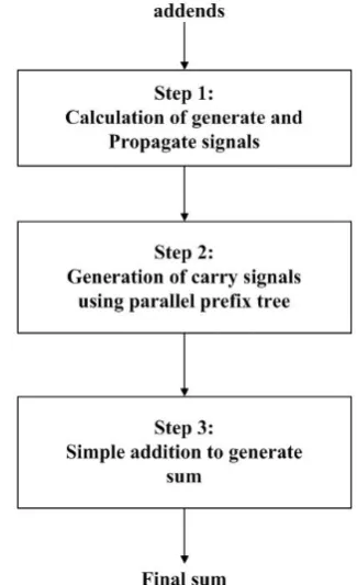
The Parallel Prefix addition is done in three steps, which is shown in Fig.1. The first step in parallel prefix addition is to calculate the generate and propagate signals. Then by using these generate and propagate signals, carry input signals of
produce the sum output. This is further discussed in detail in section II.
[image:1.595.342.505.255.522.2]
Fig.1. Addition procedure using Parallel Prefix tree structures
The aim of this paper is to propose new achitecture which uses four types of operators.In this approach the fundamental generate and propagate signals are used. By combining these primary generate and propagate signals properly by using the four types of operators, the carry input for each adder can be generated.
The rest of the paper is organized as follows: In section II, some background information about the parallel-prefix architecture is given. Proposed architecture is discussed in section III, Experimental results are presented in section IV. Conclusions are drawn in section V.
2. PRELIMINARIES
To produce the sum of two operands A and B of n-bit size, each (i)th bit of A and B are added with the carry input signal
…. (1) Computation of the carry input signal for each bit addition is the most critical and time – consuming operation. The carry- look ahead adders (CLA), gives an idea how to produce the carry input signals for an individual bit addition. This is achieved by generating two signals, the generate (gi) and
propagate (pi) using the equations:
…. (2) …. (3)
The carry in signal for any adder block is calculated by using the formula
) ….(4)
where ci must be expanded to calculate ci+1 at any level of
addition.
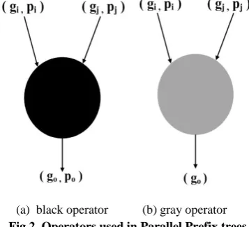
Parallel Prefix adders compute carry-in at each level of addition by combining generate and propagate signals in a different manner. Two operators namely black and gray are used in parallel prefix adders[13] are shown in Fig.2(a), Fig.2(b) respectively.
(a) black operator (b) gray operator
Fig.2. Operators used in Parallel Prefix trees
The black operator receives two sets of generate and propagate signals (gi , pi),(gj ,pj), computes one set of generate
and propagate signals (go , po) by the following equations:
…. (5)
…. (6)
The gray operator receives two sets of generate and propagate signals (gi, pi),(gj ,pj), computes only one generate signal with
the same equation as in equation (5).
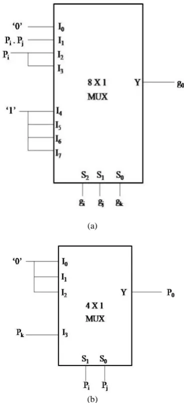
The black and gray operators are designed by using multiplexers [12] is shown in Fig.3.
(a)
[image:2.595.327.536.74.466.2](b)
Fig.3. Design of a black operator using multiplexers (a) for calculation of g0 (b) for calculation of p0
The black operator computes go value by using the inputs
gi , pi and gj , as shown in Fig.3(a), is as per the Table 1(a)
and the po value is computed by using the inputs pi , pj as
shown in Fig.3(b), is as per the Table 1(b).
Table 1(a)Truth Table to compute go of black operator
gi gj go
0 0 0
0 1 pi
1 0 1
[image:2.595.75.254.346.509.2]Table 1(b)Truth Table to compute po of black operator
pi po
0 0
1 pj
The gray operator computes only go by receiving the inputs
gi , pi and gj and it is similar to the computation of go as in
black operator, therefore Fig. 3(a) is used to implement gray operator.
O3-operator [14] which takes three pairs of generate and
propagate values and produces the generate and propagate output values is further developed as O3-black, O3-gray
operators are presented in section III.
3. PROPOSED ARCHITECTURE
A new architecture is developed by using four operators black, gray, O3-black, O3-gray operators. The black and gray
operators are already given in section III, shown in Fig.3(a), Fig.3(b) respectively. The O3-black, O3-gray operators are
shown in Fig. 4(a), Fig.4(b) respectively.
(a) O3-black operator (b) O3-gray operator
Fig.4. Operators used in hybrid Parallel Prefix trees
The O3-black operator, which takes three pairs of generate and
propagate values (gi , pi),(gj , pj), (gk , pk ) as inputs and
produces the generate and propagate output values (go , po)
as follows:
…. (7)
…. (8)
The O3-gray operator, which takes three pairs of generate and
propagate values (gi , pi),(gj , pj), (gk , pk ) as inputs and
produces only one generate signal output as per equation (7).
(a)
(b)
Fig.5. Design of a O3-black operator using multiplexers
(a) for calculation of g0 (b) for calculation of p0
Table 2(a)Truth Table to compute go of O3-black operator
gi gj gk go
0 0 0 0
0 0 1 pi . pj
0 1 0 pi
0 1 1 pi
1 0 0 1
1 0 1 1
[image:3.595.336.520.71.474.2] [image:3.595.108.227.93.171.2] [image:3.595.55.265.396.553.2]Table 2(b)Truth Table to compute po of O3-black operator
pi pj po
0 0 0
0 1 0
1 0 0
1 1 pk
The O3-black operator computes go value by using the inputs
gi , gj , gk , pi and pj , as shown in Fig.5(a), is as per the table
2(a) and the po value is computed by using the inputs pi , pj ,
pk as shown in Fig 5(b), is as per the table 2(b).
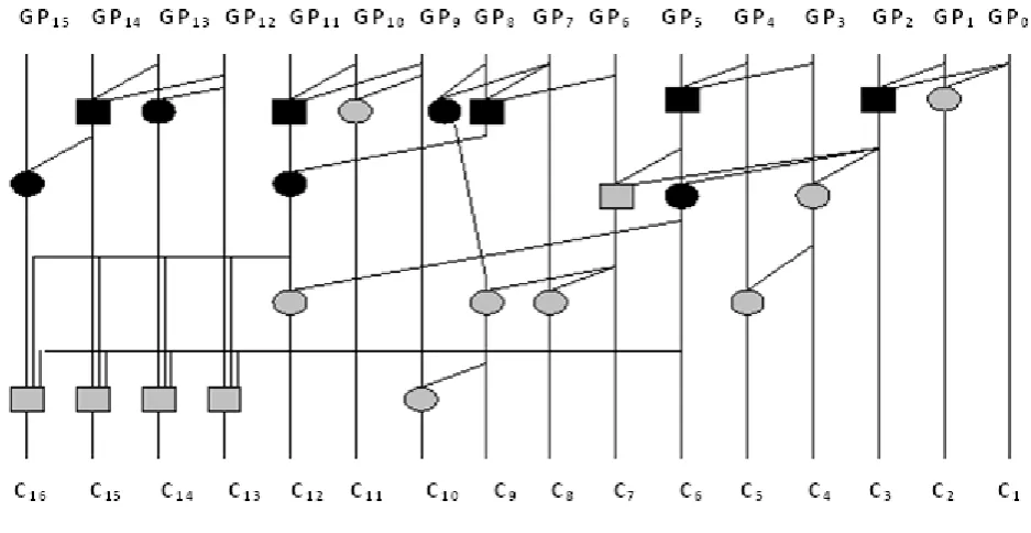
[image:4.595.49.277.94.219.2]The block diagram of 16-bit proposed parallel prefix adder using black, gray, O3-black, O3-gray operators is shown in
Fig.6.
4. EXPERIMENTAL RESULTS
The proposed 16-bit hybrid parallel prefix adder is simulated using Xilinx 9.1 version by writing a VHDL code and
choosing the device number XC3S500E. The results are tabulated in table 3. These results are compared with the other prefix adders results[12] and are tabulated in Table (4) - (7) respectively.
The comparison is done for two factors, speed and area. The speed performance can be evaluated with respect to delay and the area requirement can be estimated from the utilization of lookup tables, slices and over all gate count.
Table 4 compares the delay produced by various adders, table 5 compares the utilization of lookup tables, number of slices are compared in table 6, overall gate count is given in table 7.
Table 3 Hybrid Parallel Prefix adder Results
Delay
(ns)
Look up tables
Slices Over all gate count
[image:4.595.56.525.404.646.2]12.764 47 28 294
Fig.6. Proposed hybrid 16-bit parallel prefix adder
Table 4 Delay comparison (in nsec)
Method BK adder Skalansky
adder
KS adder HC adder LF adder Knowles
adder
Proposed Hybrid adder
Table 5 Look up table utilization comparison
Method BK adder Skalansky adder
KS adder HC adder LF adder Knowles
adder
Proposed Hybrid adder
Look up tables
47 50 82 51 48 80 47
Table 6 Slices utilization comparison
Method BK adder Skalansky adder
KS adder HC adder LF adder Knowles
adder
Proposed Hybrid adder
Slices 26 27 45 28 26 42 28
Table 7 Over all gate count comparison
Method BK adder Skalansky adder
KS adder HC adder LF adder Knowles
adder
Proposed Hybrid adder
No.of gates
297 315 501 324 309 486 294
5. CONCLUSIONS
This paper presents a hybrid architecture for parallel prefix addition. The experimental results shows that the proposed architecture is faster than the BK adder, Skalansky adder, HC adder, LF adder. The area requirement for the proposed adder is very less compared to KS adder and Knowles adder, occupies less area when compared to Skalansky adder and HC adder, and it is comparable to BK adder and LF adder. Even the KS adder and Knowles adders are slightly faster than proposed adder, they occupy very large area in an FPGA. Hence the proposed hybrid parallel prefix adder provides high speed and area efficient characteristics.
The performance of these adders can be estimated for high bit-widths. This can be further used in Cryptographic applications, where the addition of more number of bits is necessary. The new approach for the parallel prefix adders can also be used to speed up the addition process in FIR filter and arithmetic operations like multipliers, etc.
6. REFERENCES
[1] Skalansky “conditional sum additions logic” IRE Transactions, Electronic Computers, vol, EC – 9, pp, 226 - 231, June 1960.
[2] Kogge P, Stone H, “A parallel algorithm for the efficient solution of a general class Recurrence relations”, IEEE
Trans. Computers, vol.C-22, No.8, pp 786-793, Aug.1973.
[3] Brent R, Kung H, “A regular layout for parallel adders”.
IEEE Trans, computers, Vol.C-31, no.3, pp 260-264,
March1982.
[4] Ladner R, Fischer M,”Parallel prefix computation “,
J.ACM, vol.27, no. 4, pp 831-838, Oct.1980.
[5] Han T, Carlson D, “Fast area-efficient VLSI adders”,
[6] Jianhua LiuZhu, Haikun, Chung-Kuan Cheng, John Lillis, “Optimum prefix Adders in a Comprehensive Area,Timing and power Design Space”., Proceeding of the 2007 Asia and South pacific Design Automation conference.Washington,
pp.609-615,jan 2007.
[7] Taeko Matsunaga and Yusuka Matsunaga., “Timing-Constrained Area minimization Algorithm for parallel prefix adders”, IEICE TRANS, Fundamentals, vol.E90-A, No.12
Dec, 2007.
[8] Taeko Matsunaga and Shinji Kimura, Yusuka Matsunaga, “Synthesis of parallel prefix adders considering switching activities”,IEEE International Conference on computer
design, , pp.404-409, 2008
[9] Giorgos Dimitrakopoulos and Dimitric Nikolos, “High Speed Parallel –Prefix VLSI Ling Adders”, IEEE Trans on
computers, Vol.54, No.2, Feb 2005
[10]V.Choi and E.E.Swartz lander, Ir, “Parallel Prefix adder design with matrix representation”,, in Proc.17th IEEE
symp, comput.Arithmatic (ARITH), PP 90-98,2005
[11]John F.Wakerly, Digital Design Principles and Practices, 4th Edition, Pearson Education, 2009.
[12]S.V.Padmajarani and M.Muralidhar, “A New Approach to implement Parallel Prefix Adders in an FPGA”,
IJERA,Vol.2, No.4, pp. 1524-1528, July-August,2012.
[13]S.V.Padmajarani and M.Muralidhar, “Comparison of Parallel Prefix Adders Performance in an FPGA”, IJERD,
Vol.3, No6, pp.62-67 , September 2012.
[14]S.V.Padmajarani and M.Muralidhar, “A Hybrid Parallel Prefix Adder for high speed computing”, Proc.7th National
Conference on Advances in Electronics and
Communications(ADELCOs, National Engineering College, Kovilpatti, India, 2011.
[15] P.Ramanathan,P.T.Vanathi,”A Novel Power Dealy