A Conceptual Graph Petri Net Model based Multi Agent
System
Prajna Devi Upadhyay
National Institute of Technology, Durgapur,
India
Animesh Dutta
National Institute of Technology, Durgapur,
India
ABSTRACT
In this work, we propose a new formal tool called CGPN (Conceptual Graph Petri Nets) which is a combination of CG (Conceptual Graph) and CPN (Color Petri Net) to model collaborative behavior of agents in a MAS(Multi Agent System) to achieve some goals. The CG is used to represent knowledge and on the other side CPN is used to model the concurrent and dynamic aspects of a system. It is difficult to extract precise information from MAS which is dynamic in nature. Modeling MAS with CGPN will help in representing the knowledge and dynamic behavior together. Finally, the CGPN model for MAS is tested for deadlock freedom and reachability analysis to verify its correctness.
General Terms
Multi Agent SystemKeywords
Multi Agent System, Petri net, Conceptual Graph, Deadlock, Reachability.
1.
INTRODUCTION
1.1
Agents and Multi Agent Systems
An agent is a computer system or software entity that can act autonomously in an environment. Agent autonomy means that an agent has the ability to make its own decisions about what activities to do, when to do, what type of information should be communicated and to whom, and how to assimilate the information received. Thus, an intelligent agent resides in an environment and can perform autonomous actions in order to satisfy its design objective [1-5]. Multi-agent systems (MASs) [2, 5] are computational systems in which two or more agents interact or work together to perform a set of tasks or to achieve some common goals [5-8]. Human society is the best example of MAS where a number of people reside, work together and schedule their individual actions according to the requirements so that they can achieve their common or individual goals. Agents of a multi-agent system (MAS) need to interact with others toward their common objective or individual benefits of themselves. A multi-agent system can be studied as a computer system that is concurrent, asynchronous, stochastic and distributed. A multi agent system permits to coordinate the behavior of agents, interacting and communicating in an environment, to perform some tasks or to solve some problems. It allows the decomposition of complex task in simple sub-tasks which facilitates its development, test and updating.
A number of modeling tools for agents and multi agent systems have been proposed, of which Petri Nets are most common. The description of Color Petri Nets is given in the following sub section.
1.2
Color Petri Nets (CPN)
A Color Petri Net [12] is a tuple CPN = (Σ, P, T, A, N, C, G, E, I) satisfying the following requirements:
Σ is a finite set of non-empty types, called color sets.
P is a finite set of places. T is a finite set of transitions.
A is a finite set of arcs such that P∩ T = P ∩ A = T∩ A = Ø.
N is a node function. It is defined from A into P ×T
∪ T×P.
C is a color function. It is defined from P into Σ. G is a guard function. It is defined from T into
expressions such that ∀t∈T: [Type(G(t)) = Bool ∧ Type(Var(G(t))) ⊆ Σ].
E is an arc expression function. It is defined from A into expressions such that ∀a∈A [Type(E(a)) = C(p(a))MS ∧ Type(Var(E(a))) ⊆ Σ] where p(a) is the place of N(a).
I is an initialization function. It is defined from P into closed expressions such that ∀p∈P, [Type(I(p)) = C(p)MS]
There is a requirement of a tool that can represent the knowledge of the system effectively. Knowledge can be represented most effectively with the help of Conceptual Graphs (CG) [9]. A conceptual graph can be described with respect to Ontology [9]. The formal definition of a conceptual graph with respect to Ontology is given in the following subsection.
1.3
Conceptual Graph with respect to
Ontology
A Conceptual Graph [9] is a five tuple G=<C, R, type, referrent, arg1, arg2, …, argm>
C is a set of concept nodes. In Ontology[9], the set of concept types is represented by TCG.
R is a set of conceptual relations. In Ontology[9], the set of concept relations is represented by TRG.
type: C∪R→ TCG∪ TRG. It associates each concept
node to a concept type with the constraint
∀r∈R type(r) ∈ TRG and TRG = type(R)
∀c∈C type(c) ∈ TCG and TCG = type(C)
referent: C→IG associates each concept node to a
referent marker. IG is the set of distinct markers
used in association with concept nodes in C. IG is a
each argi, 1≤i≤m : R → C is a partial function
where argi(r) indicates the i-th argument of the
relation r. The argument functions are partial as they are undefined for arguments higher than the relation‟s „arity‟. We adopt the convention that arg0 indicates the (at most) one incoming arc. If
there is no incoming arc to the relation, then arg0 is
undefined. We also define the function arity(r) which returns an integer value representing the number of arguments that the relation r has. When agents need to collaborate in MAS, some knowledge has to be exchanged. Petri Nets and Color Petri Nets [12] can only represent the dynamic change of states in MAS. The exchange of knowledge among the agents which leads to change in states is not possible to be represented with the help of Color Petri Nets. Thus, there is a requirement of a tool that can represent the knowledge and dynamism of MAS effectively. The combination of Color Petri Nets and Conceptual Graphs is a new tool called Conceptual Graph Petri Nets. The new formal tool should be capable of representing that the system can reach to its final state or goal state from an intial state. The tool should also exhibit the deadlock freedom property. In this paper, we have proposed a new formal tool called Conceptual Graph Petri Nets that can represent the dynamic aspects as well as the inner knowledge of the system. We have also theoretically verified the correctness of the tool using a case study of distributed shared memory.
2.
RELATED WORK
A variety of tools have been used to model Multi Agent Systems.
2.1
Petri Nets and Color Petri Nets
Petri Nets and Color Petri Nets are system study tools that provide appropriate mathematical formalism for modeling distributed systems, also allowing analysis of the states of the system. Petri Nets have been widely used to describe the Multi Agent Systems for a long time. Color Petri Nets have been used in [13] to achieve agent scheduling in open dynamic environments. [14] uses Color Petri Nets to model an agent based interactive system. The representation of composite behaviors through Color Petri Nets has been done in [15]. The fundamentals of an agent‟s social behavior in a Multi Agent System have been modeled with the help of Color Petri Nets taking the packet world scenario as a case study in [16]. [17] uses Petri Nets to model the abstract architecture for intelligent agents and structural analysis of the net provides an assessment of the interaction properties of Multi Agent Systems. Deadlock Avoidance in Multi Agent System is considered and is evaluated using the liveness and boundedness property of the Petri Net Model. [18] introduce a Color Petri Net model to represent flexible agent interactions.
2.2
Agent Petri Nets
Agent Petri Nets [19] is a new formalism for modeling Multi Agent System which is able to describe not only the internal state of each agent modeled but also its behavior. Hence, one can naturally model the dynamic behavior of complex systems and the communication between these entities.
2.3
Predicate transition Nets
Predicate Transition Nets [20, 21] are a high level formalism of Petri Nets for modeling and analyzing Multi Agent behaviors. In MAS, how agents accomplish goals is specified by plans built from individual actions. Predicate Transition
Nets allow us to make sure that the plans are reliable. Here, planning graphs have been used to perform the reachability analysis.
2.4
CGP-Nets
CGP Nets have been introduced in [22] which is a hybrid model binding Conceptual Graphs and Color Petri Nets to represent Multi Agent Systems. It has been used to model proactivity in Multi Agent Systems. There is a lack of formal proof of the correctness of the model given in this work.
3.
SCOPE OF THE WORK
Although a number of tools have been proposed to model Multi Agent System, but they lack the ability to represent the inner knowledge of the system. The available tools so far, like Petri Nets or Color Petri Nets, can only model the dynamic aspects of the system, like concurrency, synchronization or mutual exclusion. There is a need for a tool that can express the knowledge of a Multi Agent System in the form of properties, capabilities and requirements of the system. In this paper, we present an extended definition of CGP Nets which is a binding between Conceptual Graphs and Color Petri Nets. With this CGPN tool, the multi agent collaboration is modeled and a formal proof of the reachability and deadlock- freedom is provided.
4.
FORMAL DEFINITION OF MAS
MAS can be formally defined in the following way:
State_concept={s1, s2,…, sr}, r∈N be the set of
different conditions of the system.
Au={a1‟,a2‟,…,as‟},s∈N be the set of all agents
available in the universe.
Tu={t1‟,t2‟,…,tt‟}, t∈N be the set of all tasks that
can be performed in the universe.
A={a1, a2, …, ap}, p∈N be the set of agents that are
a part of the system.
T={t1, t2, …, tq}, q∈N be the set of tasks that can be
performed in the system.
Set={A, T}, is a set of sets, consisting sets A and T. Let able(ai,tj), 1≤i≤s, 1≤j≤t be a function which is
true if an agent ai is able to perform a task tj, able:
AuxTuBool
Let belong be a function. belong : (AU∪ TU)X Set Bool
Let GL={G1,G2,…,Gn} be the set of goals the
system may have, Gi=P(S), 1≤i≤n, P(S) denotes the
power set of S.
Let perceive(ai,tj,sk), 1≤i≤p,1≤j≤q,1≤k≤r be a
function which is true under the following condition:
∃ai ∃tj [ able(ai,tj) ∧ belong(ti,T) ∧ belong(ai,A) ∧ sk
is the state perceived by performing the task tj by
agent ai]| ai∈AU, tj∈TU, sk∈S ↔perceive (ai, tj, sk)
req: P(S)P(TU), req is a function that maps a set
of states to some set of tasks in TU.
Lead: P(TU) X P(S)P(S), lead is a function that
maps a set of tasks and set of states to a new set of states.
R: TUBool, R(ti) indicates requirement for
performing a task has arisen, ti∈TU
completed successfully, ti∈TU
State_relation is the relation that relates different conditions of state_concept that are true at any instant.[image:3.595.55.288.96.376.2]
5.
MAS COORDINATION ONTOLOGY
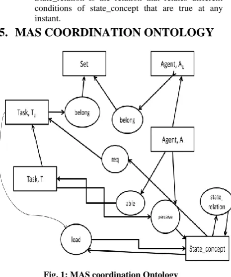
Fig. 1: MAS coordination Ontology
The Ontology diagram shown in figure 1 describes the MAS coordination Ontology. We have,
TCO={Set, AU, A, TU, T, State_concept}
TRO={belong, req, able, lead, perceive,
state_relation}
≤(T, TU)=true, ≤(A, AU)=true
B(state_rel)={state_concept} B(req)={state_concept, T} B(belong)={TU, AU, Set}
B(perceive)={T, A, state_concept} B(lead)={T, state_concept} B(able)={A, T}
Here, the different concepts are shown as rectangles and relations are shown as ovals. The instances of State_concept, A, and T are application specific. A conceptual graph adhering to this Ontology forms a token for the Conceptual Graph Petri Net. At any instant, the CG formed from the State_concept and state_relation describes the state of the system.
6.
FORMAL PROOF OF THE SYSTEM
We have proposed the CGPN tool to represent the dynamics as well as knowledge of MAS. The CGPN tool uses conceptual graphs to represent the knowledge of MAS. Since conceptual graphs cannot exist in isolation, Ontology is used to describe the framework of domain knowledge. Thus, CGPN is dependent on the Ontology for its existence. The following shows some of the dependency relations on the Ontology we have proposed.
6.1
Dependency relations
The system determines all the functions that are true in the system:
∀ sk perceive(ai, tj, sk), sk ∈ S, tj∈TU, ai∈AU
∀ tj able(ai,tj), tj∈T, ai∈AU
Let the initial states be s1 ∧ s2 ∧ … ∧ sx. If the following
is true,
∀sk ∃ai ∃tj [perceive(ai, tj, sk)]| ai∈ Au, tj ∈ Tu, 1≤k≤x,
k,x ∈ N, then we can write:
{s1 ∧ perceive(a1, t1, s1)} ∧ {s2 ∧ perceive (a2, t2, s2)}
∧… ∧ {sx ∧ perceive(ax, tx, sx)}=true
Being able to perceive the states, the system finds out a requirement to perform some tasks. So we can write: {s1 ∧ perceive(a1, t1, s1)} ∧ {s2 ∧ perceive(a2, t2, s2)}
∧… ∧ {sx ∧ perceive(ax, tx, sx)}↔R(t1 ‟
) ∧ R(t2 ‟
) ∧…∧ R(ty‟), ti‟∈Tu, 1≤i≤y, y∈N where R(ti‟) indicates a
requirement has arisen for some task ti‟∈Tu.
When the requirement for a task arises, the system searches for agents who can perform the task. We say that a task is successfully completed if and only if R(ti‟) ∧∃az [able(az, ti‟) ∧ belong(ti‟, T) ∧ belong(az,A)],
az ∈ Au , 1≤i≤y, ti‟∈Tu= true, so [R(ti‟) ∧∃az [able(az,
ti‟) ∧ belong(ti‟, T) ∧ belong(az,A)], az ∈ Au , 1≤i≤y,
ti‟∈Tu]↔S(ti‟)
If all the tasks whose requirement had arisen are completed successfully, then it leads to a change in state.
S(t1‟) ∧ S(t2‟) ∧…∧ S(ty‟) ↔ s1 ∧ s2 ∧ … ∧ sa, 1≤a≤r, it
leads to a new state of states which can be perceived as stated earlier. If we perform all the tasks required by the system and the final state the system reaches is equivalent to the goal, we can say that the goal is achievable.
6.2
Lemmas
6.2.1 Lemma 1. The set of agents, A1, employed to perform a
set of tasks leading to the achievement of some goal, Gx, is a
subset of A.
Proof: To prove the above lemma, proof by contradiction has been used. Let us assume the following:
T1={t1,t2,…,tp} is the set of tasks that have been performed
to achieve the goal, Gx A1={a1,a2,…,aq} is the set of agents
that have performed the task set T1. A1⊄A i.e A1
-A≠∅={a1,a2,…,as}, s>=1and ∀ ti∈T1, let belong(ti, T)=true
1. Goal Gx is achieved
2. ∀ tj S(tj) = true| tj∈T1,
3. ∀ az able(al, tm) = true| az ∈A1, where az has
performed some task tm in T1
4. So, [∀ an able(an, to)=true] ∧ [ R(to)=true] an∈A1-A,
where an has performed some task to∈T1….(from 3,
A1-A⊆A1)
5. ∀ an belong(an, A)=false| an∈A1-A
6. ∀ an [able(an, to) ∧ belong(an, A) ∧ belong(to,
T)]=false, an∈A1-A ,to∈ T1, to is the task performed
by an …(from 4, 5, 6)
7. ∀ an [R(to) ∧ able(an, to) ∧ belong(an, A) ∧ belong(to,
T)]=false, an∈A1-A ,to∈ T1, to is the task performed
8. ∀ an S(to) = false, an∈A1-A ,to∈ T1, to is the task
performed by an …(from format of dependency)
8 is in contradiction with 2. Our assumption, A1-A≠∅ was
false. Therefore, A1 ⊆ A. Hence, the lemma stands true.
6.2.2 Lemma 2. Given the goal is acheived, the set of tasks performed to achieve the goal is always a subset of T. Proof: The following derivation uses proof by contradiction. Let us assume the following: T1={t1,t2,…,tp} be the set of
tasks that have been performed to achieve the goal, A1={a1,a2,…,aq} be the set of agents that have performed the
task set T1, ∀ aj belong(aj, A)=true aj∈A1 and ∀ ti
R(ti)=true|ti∈T1
Let us assume T1⊄T i.e T1-T≠∅.
1. Goal is achieved. 2. ∀ ti S(ti) = true| ti∈T1,
3. ∀ ti∃ aj able(aj,ti)=true | aj∈A1 ,ti∈T1
4. ∀ ti belong(ti, T)=false| ti∈T1-T
5. ∀ ti [able(aj,ti) ∧ belong(ti, T) ∧ belong(aj, A)] =
false| ti∈T1-T, aj∈A1, able(aj,ti)=true…(from 3,4,5)
6. ∀ ti R(ti)=true|ti∈T1…(given)
7. ∀ ti [R(ti) ∧ able(aj,ti) ∧ belong(ti, T) ∧ belong(aj,
A)] = false| ti∈T1-T, aj∈A1, able(aj,ti)=true …(from
6,7)
8. ∀ ti S(ti) = false| ti∈T1-T …(from format of
derivation 3)
8 is in contradiction with 2. Our assumption, T1-T≠∅ was
false. Therefore, T1 ⊆ T. Hence, the lemma stands true.
6.2.3 Lemma 3. Given the goal is achieved, the set of states reached is always perceivable.
Proof: Here, proof by contradiction has been used similar to the previous cases. Let us assume the following:
T1={t1,t2,…,tp} be the set of tasks that have been
performed to achieve the goal, A1={a1,a2,…,aq} be the set of
agents that have performed the task set T1.
Let us assume that for some state Sb=sb1∧ sb2 ∧…∧ sbc ≠Gb
generated in the sequence of derivations, ∄ tc ∃sbi
perceive(ad,tc,sbi)=true| tc∈T1, sbi, 1≤i≤c, ad∈ A1.
1. Goal Gb is achieved.
2. ∀ ti S(ti) = true| ti∈T1,
3. {sb1 ∧ perceive(a1,t1,sb1)} ∧ {sb2 ∧
perceive(a2,t2,sb2)} ∧ …∧ {sbc ∧
perceive(ac,tc,sbc)}=false…(given)
4. R(t1) ∧ R(t2) ∧…∧ R(tk) =false, where t1, t2,…, tk are
the tasks whose R(tk) would have been true if
perceive(ad,tc,sbi)=true ∀ sbi, 1≤i≤c , ad∈A1, tc∈T1
5. Sb is the final state
6. Sb≠Gb
7. Gb is not achieved
7 is in contradiction with 1. So, our assumption was false. Hence, the lemma stands true.
7.
CONCEPTUAL GRAPH PETRI NETS
A conceptual graph Petri net is a tuple (CG, P, T, A, N, G, E, I)
CG is a conceptual graph type P is a finite set of places T is a finite set of transitions
A is a finite set of arcs such that P∩T= P∩A= T∩A=∅
N is a node function defined from A into PXT ∪ TXP
G is a guard function defined from T into expression such that ∀t∈T [Type(G(t))=B∧ Type(Var(G(t)))=CG. Each transition is mapped into a Boolean expression by a guard function such that Type (G(t))=B, where B = B1 ∧ B2, where,
B1: boolean expression denoting the transition
enabling condition
B2: boolean expression denoting the transition
executing condition.
The expression B1 represents that the system, with
the help of its agents, can perceive the states that are input places of the transition. The expression B2
represents that a requirement of some task has arisen and there exist some agents in the system which can perform this task.
E is an arc expression function defined from A into expressions such that ∀a∈A Type(E(a))=CG and Type(Var(E(a)))=CG
I is an initialization function that maps every place to a CG, I:P→CG
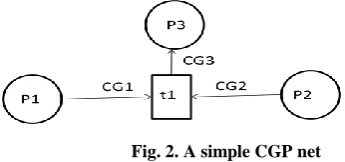
[image:4.595.315.488.464.545.2]A CGP net can be represented as given in Figure 2.
Fig. 2. A simple CGP net
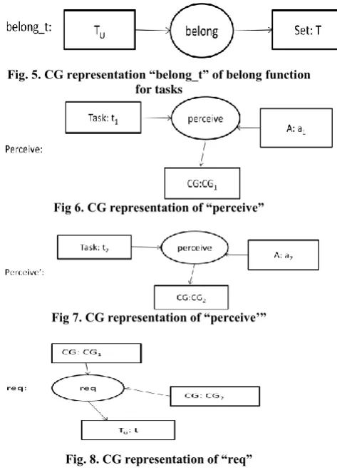
We can represent the functions able, belong and req as conceptual graphs in figure 3, 4, 5, 8.The perceive function for CG1and CG2 is shown in figure 6 and figure 7.
Fig. 3. CG representation “able” of able function
Fig. 5. CG representation “belong_t” of belong function for tasks
Fig 6. CG representation of “perceive”
Fig 7. CG representation of “perceive’”
Fig. 8. CG representation of “req”
The transition t1 in figure 2 can be expressed as
Type(G(t1))=B, where
B=[{CG1 ∧ perceive} ∧ {CG2 ∧ perceive‟}] ∧ [req ∧ able∧
belong_a ∧ belong_t]. Here, B1={CG1 ∧ perceive} ∧ {CG2 ∧
perceive‟} is the enabling condition of the transition and B2=
req ∧ able ∧ belong_t ∧ belong_a is the executing condition of the transition. From the CGPN model, we can verify the reachability and deadlock freeness of the model. We can map the CGPN model into a simple Petri net model by considering the special tokens of CGPN as plain tokens and assigning all the arc weights as 1. Let the initial state of the Petri net be M0.
A marking Mj is said to be reachable from marking Mi if there
exists a sequence of transitions that takes the Petri net from Mi
to Mj . The set of all possible markings that are reachable
from M0 is called the reachability set and is defined by R(M0).
If I is the incidence matrix of the model, then the reachability criterion can be specified by the following matrix equation:
𝑀𝑖 + 𝐼. 𝜎 = 𝑀𝑗 (1) where I is the incidence matrix of the Petri Net and σ is the sequence of transitions[11]. This is a necessary but not sufficient condition. We can map the sequence of transitions of the CGPN to the steps of formal derivation as given in section 6. If a transition has fired, it indicates that the enabling condition and the executing conditions for the transition are true. Firing of a transition in the CGPN takes us to a new state. Similarly, the enabling and the executing conditions both being true for a transition means the task has successfully completed and it leads to some new state. If the goal state in the CGPN is reachable, it indicates that goal can be achieved through formal derivation. The deadlock freedom of the model can also be proved using algebraic techniques [23]. In terms of Petri net, a deadlock corresponds to a marking from
where no transition is fire able. So, every reachable deadlock is a solution of the state equation where every transition is disabled. If we can prove that these markings are never reachable, then we can prove that the Petri net is deadlock free. So, the following is a basic, general, sufficient condition for deadlock freedom:
Let S be a Petri net system. If there is no solution to
𝑀𝑗 − 𝐼. 𝜎 = 𝑀𝑖 𝑀𝑗, 𝜎 ≥ 0
∨ 𝑚 𝑝 < 𝑃𝑟𝑒 𝑝, 𝑡 ∀𝑡𝜖𝑇, ∀𝑝 𝜖 . 𝑡 (2) where Pre[p,t] is the minimum no. of tokens required in place
p to enable the transition t, ∙t is the set of all input places of transition t, m[p] is the number of tokens in place p, Mi is the
initial state, Mj is the state formed after finding out m[p] for
every place and σ is the sequence of transitions, then S is deadlock free.
8.
CASE STUDY
We have used the brick problem [17] as an example to model this scenario. It consists of 2 agents, A and B, which are collaboratively working to move bricks from end 2 to end 1. End 1 consists of a pile of bricks which should be transferred to end 2 with the help of both agents. Agent A and B both start moving towards end 2 from end 1. Since agent A moves faster than B, it reaches end 2 earlier. It takes a brick and starts moving towards end 1. Meanwhile, it crosses B and hands over the brick to it. A then moves towards end 2 to collect another brick and B moves towards end 1. When it reaches end 1, it places the brick there. The coordination between the agents continues until all the bricks from end 2 are transferred to end 1. This is the goal that is to be achieved by the system.
8.1
CGPN Model
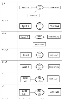
[image:5.595.326.526.531.681.2]The CGPN model of the bricks problem is shown in Fig. 10. It has 11 states and 9 transitions. The outgoing and incoming arcs to and from places have tokens describing those places. The description of the tokens is given in the following table:
Fig 10:CGPN model for the bricks problem
Table 1: CG description of places
Token label Conceptual Graph
a, o, z
b
c, d, y
e, f
g, h
r, i
j, k
u, v, x
m, n
w, q, s
p, l, t
a1
a2
In order to prove that the goal state is reachable, we can use the matrix equation for reachability of a marking.
8.2
Proof for Reachability
Let us assume that the number of bricks at end 2 initially is 1. This can be represented in CGPN by assigning number of tokens to place p12 as 1. So, the goal state should contain 1
brick at end 1. In CGPN, the goal state marking should have 1 token in place p13. For 1 brick, the reachability graph is shown
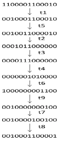
in Fig 11. From the initial state, there exists a sequence of transitions that lead us to the goal state, i.e marking 0010001100001. The final marking indicates that all bricks from end 2 have been transferred to end 1. If the number of bricks is more than 1, then the same sequence of transitions will be fired until number of tokens in place p13 is equal to the
[image:6.595.56.293.72.312.2]Fig 11: Reachability graph for CGPN
Here, the initial state is Mi=[1100001100010]‟, the final state
is Mj=[0010001100001]‟, and we have σ=[111111111]‟, for
which
𝑀𝑖 + 𝐼. 𝜎 = 𝑀𝑗 i.e
1 1 0 0 0 0 1 1 0 0 0 1 0 ′+ 𝐼. 1 1 1 1 1 1 1 1 1 ′=
0 0 1 0 0 0 1 1 0 0 0 0 1 ′
8.3
Proof for deadlock freedom
A deadlock is a marking from which no transition is enabled. From the CGPN model shown in Fig. 6, specifying the deadlock conditions in the form of inequalities, the following set of inequalities should be solved, where pi is the number of
tokens present in place pi, 1≤i≤13
𝑝1 + 𝑝2 ≤ 1 (disabling condition for t1) (3)
𝑝3 + 𝑝12 ≤ 1(disabling condition for t2) (4)
𝑝4 ≤ 1(disabling condition for t3) (5)
𝑝5 + 𝑝6 ≤ 1(disabling condition for t4) (6)
𝑝7 + 𝑝8 ≤ 1(disabling condition for t5) (7)
𝑝7 + 𝑝9 ≤ 1(disabling condition for t6)
(8)
𝑝11 ≤ 1(disabling condition for t7) (9)
𝑝8 + 𝑝11 ≤ 1(disabling condition for t8) (10)
𝑝10 + 𝑝1 ≤ 1(disabling condition for t9) (11)
Solving these inequalities, the solution obtained for p1 to p13 is
[0010010000001]‟, which is the next state reached after transition t5 fires from the goal state i.e. [0010001100001]. It
indicates that as long as the goal state is not reached, deadlock does not occur.
9.
CONCLUSION
In this paper, we have defined a formal tool called CGPN to model the collaboration of agents in a Multi Agent System. It has been shown that the CGPN tool is more expressive in representing the inner knowledge of the MAS. The model has also been tested for reachability analysis and deadlock freedom. The system modeled so far is reactive, so the future prospect of the work will be to model proactivity in the system and represent it with the help of CGPN.
10.
REFERENCES
[1] Rouff, C.A., Hinchey, M., Rash, J., Truszkowski, W., and Gordon-Spears, D. (Eds). 2006. “Agent Technology from a formal perspective” (Springer-Verlag London Limited 2006).
[2] Weiss, G., Ed., “Multiagent systems: a modern approach to distributed artificial intelligence”, (MIT Press, 1999).
[3] N. J. Nilsson, “Artificial intelligence: a new synthesis”, (Morgan Kaufmann Publishers Inc., 1998).
[4] S. J. Russell and P. Norvig,” Artificial Intelligence: A Modern Approach”, (Pearson Education, 2003).
[5] M. J. Wooldridge, “Introduction to Multiagent Systems”, (John Wiley & Sons, Inc., 2001).
[6] A. Idani, “B/UML: Setting in Relation of B Specification and UML Description for Help of External Validation of Formal Development in B”, Thesis of Doctorat, The Grenoble University, November 2005.
[7] G. W. Brams, “Petri Nets: Theory and Practical”, Vol. 1-2, (MASSON, Paris, 1982).
[8] M-J. Yoo, “A Componential For Modeling of Cooperative Agents and Its Validation”, Thesis of Doctorat, The Paris 6 University, 1999.
[9] P.H.P. Nguyen, D. Corbett, “A basic mathematical framework for conceptual graphs”, In: IEEE Transactions on Knowledge and Data Engineering, Volume 18, Issue 2, 2005.
[10] John F. Sowa, Conceptual Graphs, in “The Handbook of Knowledge Representation”, ed. F. van Harmelen, V. Lifschitz, and B. Porter, (Elsevier, 2008), pp. 213-237.
[11] John F.Sowa, “Knowledge Representation: Logical, Physical and Computational Foundations” (Thomson Brooks/Cole, 2000)
[12] K. Jensen, “Color Petri Nets – Basic Concepts, Analysis Methods and Practical Use”, volume 1: Basic Concepts, (Springer-Verlag, Berlin 1992).
[13] Quan Bai, Minjie Zhang and Haijun Zhang, “A Coloured Petri Net Based Strategy for Multi-agent Scheduling”, Proceedings of the Rational, Robust, and Secure Negotiation Mechanisms in Multi-Agent Systems (RRS‟05)
[14] Vedran Kordic, “Petri Net,Theory and Applications, in, Use of Petri Nets for Modeling an Agent-Based Interactive System: Basic Principles and Case Study” ed. Houcine Ezzedine and Christophe Kolski,( I-Tech Education and Publishing, Vienna, Austria, 2008) , pp. 534
[16] Danny Weyns, Tom Holvoet, “A Color Petri Net for Multi Agent Application”.
[17] Jose R. Celaya, Alan A. Desrochers, and Robert J. Graves, “Modeling and Analysis of Multi-agent Systems using Petri Nets”, Journal of Computers, vol. 4, no. 10, October 2009
[18] Quan Bai, Minjie Zhang and Khin Than Win, “A Color Petri Net Based Approach for Multi-agent Interactions”, 2nd International Conference on Autonomous Robots and Agents, December 13-15, 2004 Palmerston North, New Zealand.
[19] Borhen Marzougui, Khaled Hassine, Kamel Barkaoui, “A New Formalism for Modeling a Multi Agent Systems: Agent Petri Nets”, J. Software Engineering & Applications.3(2010) 1118-1124
[20] Dianxiang Xu, Richard Volz, Thomas Ioerger, John Yen, “Modeling and Verifying Multi-Agent Behaviors Using Predicate/Transition Nets”, SEKE ‟02.
[21] Tadao Murata, Peter C. Nelson, “A Predicate-Transition Net Model for Multiple Agent Planning”, Information Sciences (1991) 57-58, 361-384
[22] J.-D. Vally, R. Courdier, “Hybrid Model to Design Proactivity and Multi-Agent-Systems”, 2002 World Scientific and Engineering Society (WSES) Intern. Conference on evolutionary computations, 2002