http://dx.doi.org/10.4236/wjet.2015.33010
Theoretical Analysis of Gin Cylinder for
Simulating Dual Saw Cylinder Chamber
Gin for Increasing Wear Proof,
Energy Efficient, Saving Resources
Shuhrat Mamamtovich Azizov, Hamid Tursunovich Axmedhodjaev
Mechanical Engineering, Namangan Institute of Engineering and Technology, Namangan, Uzbekistan Email: [email protected], [email protected]
Received 17 April 2015; accepted 10 July 2015; published 13 July 2015
Copyright © 2015 by authors and Scientific Research Publishing Inc.
This work is licensed under the Creative Commons Attribution International License (CC BY).
http://creativecommons.org/licenses/by/4.0/
Abstract
In our work we consider prevent wear of the saw tooth saws cylinder and shaft by mathematical analysis of the saw cylinder at different shaft lengths and number of blades. To prevent wear on cutting cylinder, we determine the optimal cross-flexural vibration of the shaft with respect to time and along the length of the shaft. Model simulated the transverse vibrations with different amounts of drinking and between saw gaskets brought the best option, which has a positive effect on the strength of the shaft. As a result, we have developed two staggered cylinders saw in one of the working chamber gin, which reduces bending vibration, but it increases efficiency.
Keywords
Gin, Working Chamber Saw Two Cylinders, Vibrational Loads, Dynamic Loads Styling, Shaft Is Stabilized Insert, Saving Resources
1. Introduction
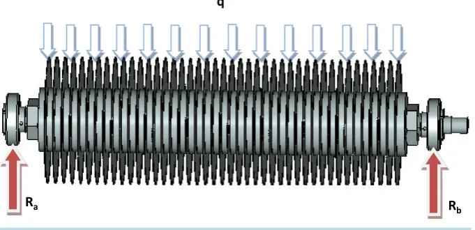
buted force q (Figure 1).
0
cos ;
2 2
OQA
r h
OQ OA α ∆
− =
From a right triangle Here: r: Radius saws;
h0: The optimum distance between the tip of the saw and grate
0
cos 1
2 2
h
α
= − (1)
0
0
arccos 1
2 2
2 arccos 1 2
h
h
α
α
= −
= ⋅ −
(2)
If: r=16 cm,h0=5 cm; then (2) the formula is determined by the angle of the contact zone of the saw cy-linder with raw roller
0 5 1 2
2 arccos 1 2 arccos 1 2 arccos 1 2 arccos
16 3 3
h r
α = − = − = − =
(3)
2 arccos 0.66 2 63 126
α = × = × =
2π 2 arccos 0.5 120
3
α≈ = =
Using this formula, we find the effective length of the contact area of the cylinder saw in the distance (AB)
π 2π 2 3.14
2 16 16 33.4сm
3 3 3
AB= ⋅ = × ⋅ =α r r × = × × = (4)
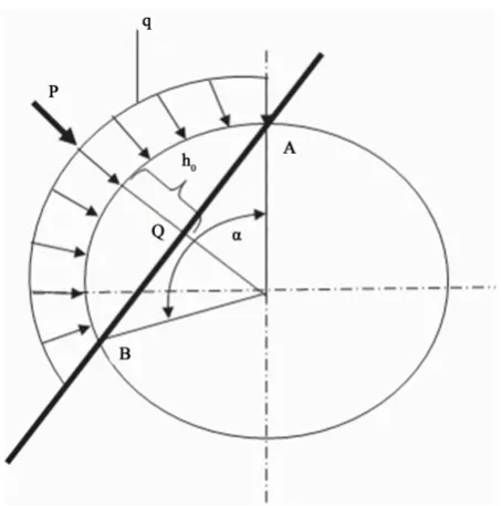
[image:2.595.144.485.546.711.2]The intensity of the load of cotton at the gin and one saw cylinder (Figure 2) is determined by the following formula
Figure 1. The impact force is uniformly distributed. q
Figure 2. Shows the angle of the contact zone of the saw cylinder with raw roller.
6kg kg
0.18
33.4 cm
q= =
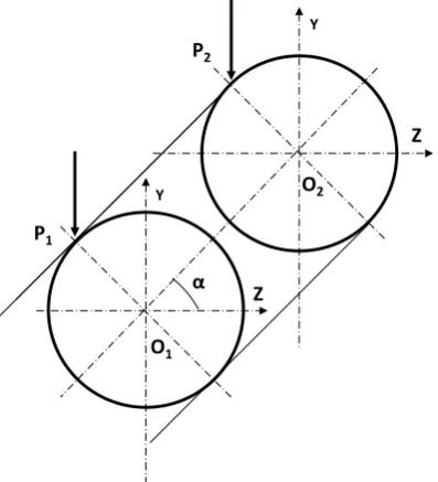
For single chamber gin with two circular saw-cylinder (Figure 3) arranged at a certain angle α intensity of the load of cotton into first and second respectively, the saw is determined by the following formula [3] [4]
1 1
2 2
2 kg
0.06 ;
33.4 cm
4 kg
0.12
33.4 cm
p q
AB p q
AB
= = =
= = =
(5)
3. Theoretical Dynamical Analyze of Saw Cylinder
Now we have to find the dynamic load on the first and second saw cylinder. To do this, we need to determine the angular and tangential speed of the first and second saw the cylinder. The angular velocity of the first and second cylinder saw is the same.
It is 700 rev/min. So the formula
1 2
1
2
rev 700 ;
min rev 700 ;
min
ϖ ϖ ϖ
ϖ
ϖ
= =
=
=
From the following formula, we find tangential speed
cm m
700 16 11200 112
min min
v= ⋅ =ϖ r × = = (6)
Determination of dynamic load fluctuations of the shaft of the saw gin under its own weight, drank and between pads.
Figure 3.Show’s the distribution of raw power roller two saw cylinder.
Saw cylinder subjected to the bending to pressure from its own weight of the shaft, saws and between pads and cotton. [1], [4] and [5] Thus, the shaft is subjected to transverse flexing. When ginning cotton, lateral bending of the shaft is accompanied by oscillations, which affect the strength of the shaft. This process is discussed in the next model of the structure (Figure 4). Let shaft gin is a beam of circular cross-section hinged on two pillars.
Let Ζ—abscissa of this section of the shaft, measured from some fixed origin, t—time.
Then the differential equation of bending of the shaft on the basis of the Lagrangian is written in the following form
4 2 2
4 2
d y y
EJ m q y
g
z t
ϖ ∂
= − −
∂ ∂ ⋅ (7)
Here: EJ—The flexural rigidity of the shaft;
m—The mass of the shaft with the weight of the saw;
ω—Circular shaft speed;
g—Acceleration of gravity of the body.
In Equation (7) the right side represents the intensity of the load at the point z at time t and comprises two members:
m—Load inertia is the mass per unit length of the shaft;
q—Uniformly distributed load of cotton with the shaft rotation and speed.
Some interest research process shows properties of free oscillations. When these vibrations bent axle shaft will no longer remain constant over time, and will present its equation is a function of two variables:
( )
,y=y z t (8)
We write the Equation (7) form:
4 2
4 2 0
y y
a by
z t
∂ ∂
+ + =
∂ ∂ (9)
where:
2
1 2
, ,
m q
a b m m m
EJ EJ g
ϖ ⋅
= = = +
⋅ ;
m1—weight shaft;
m2—weight between saw blade and gaskets;
q—intensity of cotton.
P1
O2
O1
Z
Z
Y
Figure 4.Design scheme shaft dynamic load on the lateral bending.
Restricted conditions:
( )
( )
( )
( )
( )
0; ; 0; ; 0; ; 0;
0; ; 0; ( ; ) 0; ; 0
x y o t y o t y o t
x y l t y l t y l t
= = = =
= = = =
(10)
The initial conditions:
( )
( )
( )
0;
0; ; 0; ; 0; y z o ;
t y z o y z o
t φ
∂
= = = =
∂
(11)
Here φ0—the initial angle of rotation of the shaft.
Equation (9), the boundary conditions (10) and the initial conditions (11) satisfies the function: π
Sinn z Sin
y A pt
l
= ⋅ ⋅ ⋅ (12)
Here: p—The angular frequency of the shaft bending;
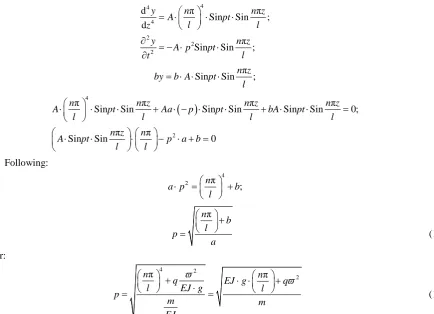
A—The amplitude of the vibrations of the shaft. Substituting (6) into (3) we obtain:
4 4 4 2 2 2
d π π
Sin Sin ; d
π Sin Sin ;
y n n z
A pt
l l
z
y n z
A p pt
l t = ⋅ ⋅ ⋅ ∂ = − ⋅ ⋅ ∂ π Sin Sinn z;
by b A pt
l
= ⋅ ⋅ ⋅
( )
4
2
π π π π
Sin Sin Sin Sin Sin Sin 0;
π π
Sin Sin 0
n n z n z n z
A pt Aa p pt bA pt
l l l l
n z n
A pt p a b
l l ⋅ ⋅ ⋅ + ⋅ − ⋅ ⋅ + ⋅ ⋅ = ⋅ ⋅ ⋅ − ⋅ + = Following: 4 2 π ; n
a p b
l ⋅ = + π n b l p a +
= (13)
or:
4 2
2
π π
n n
q EJ g q
l EJ g l
p m m EJ ϖ ϖ + ⋅ ⋅ + ⋅
= = (14)
We obtain the second order differential equation in the form (15) with the transition to (9)
( )
( )
( )
( )
( )
( )
4
4
π Sin π Sin π Sin π 0;
π π
Sin 0;
n n z n z n
f t a f t b f t
l l l l
n n
z f t af t b f t
l l ⋅ ⋅ + ⋅ ′′ + ⋅ ⋅ = ′′ ⋅ ⋅ + + ⋅ = Or
( )
( )
0;f′′ t + ⋅k f t = (16)
Here: 4 π n b l k a + = Initial conditions:
( )
0 0;( )
0 0;f = f′′ =φ
The general integral Equation (10) will be:
( )
1Cos 2Sinf t =C k t⋅ +C k t⋅ (17)
C1 and C2-constants are determined from the initial conditions:
( )
0 1 0f =C =
( )
02 0 2
0 C ;
f k C
k φ φ
′′ + ⋅ = =
Then a particular solution has the form:
( )
0 Sinf t k t
k φ
= ⋅ ⋅ (18)
Thus the solution of (15) with (18) will have the form:
( )
0 π; Sinn Sin
y z t z k t
l k φ
= ⋅ ⋅ (19)
4. Conclusions
As a result, we have developed, gin, which reduces bending vibration, but it increases performance by two stag- gered cylinders saw in one of the working chamber. This arrangement of the saw cylinders in one working chamber causes the separation of the dynamic loads on the two zones and reduces the load on the saw cylinder twice [4]. This factor increases the durability and saving recourses. Being in a working chamber saw two cylinders reduces the time to separate the fibers from the seed. In similar gin in the same cell is one saw cylinder to completely separate the fiber from the seed cotton should contact with the saw cylinder five. In our proposed gin this time is cut in half and allows increased energy-efficiency.
units, distributed along the length of the shaft 8, the maximum and minimum pulse loads. Analysis of the graphs shows that the amount of 80 pieces saws, shaft strength is ensured, but the performance of the output fiber becomes smaller.
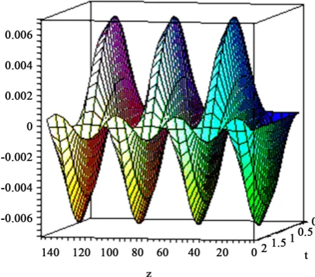
In this (Figure 6) shows the variation in the longitudinal bending of the shaft, depending on the time t and the shaft length z. The following graph shows the oscillatory processes of the shaft, with the amount of drinking 90 saw units, distributed along the length of the shaft 6 three drums maximum and minimum vibrational loads with a large distance along the shaft. Which is close to the process of formation of the resonant transverse bending. This negatively affects the strength of the shaft.
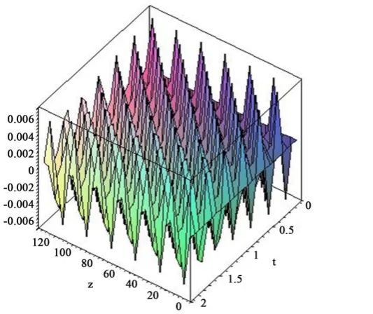
In Figure 7 with the number of 120 pieces drinking occurs uneven distribution of the maximum and minimum vibration loads chaotic distance along the length of the shaft. This is the process of producing resonant transverse bending. This negatively affects the strength of the shaft.
[image:7.595.196.425.253.454.2]In Figure 8 shows the longitudinal bending fluctuations for 60 saw. In this case the transverse oscillation shaft bending time and the length of the shaft is stabilized, which has a positive effect on the strength of the shaft. By
[image:7.595.182.455.480.707.2]Figure 5. Longitudinal bending fluctuations for 80 saw cylinder.
Figure 7.Longitudinal bending fluctuations for 120 saw cylinder.
Figure 8.Longitudinal bending fluctuations for 60 saw cylinder.
arranging the two saw cylinders in the same cell, the amount of drinking is 60 pieces for each cylinder of the saw. This is turn provides increased strength and durability performance of the output shaft of the fiber. On the other hand decreases the density in the working chamber of gin. At time t = 1 s oscillatory process becomes stable, which corresponds to the optimal operation of the saw gin.
References
[1] Miroshnechenko, G.I. (1972) Bases of Designing of Machines of Primary Processing of Cotton. Book Theory of Gin-ning Machine, Moscow.
[2] Mamatovich, A.S. and Abdusamat, K. (2011) Definition of Increasing the Fibre Capturing Surface of Saw Teeth of Cotton Ginning Machine through Mathematic Modelling. World Journal of Mechanics, 1, 122-126.
http://dx.doi.org/10.4236/wjm.2011.13017
[image:8.595.200.467.316.540.2]the Problem Mechanics, 3, 30-32.
[4] Mamatovich, A.S., Abdusamat, K. and Arras, P. (2013) The Mathematical Simulation of Brush Drums in a Dual Saw Cylinder Chamber Gin for the Purpose of Increasing the Quantity of Captured Cotton Fiber from Saw. World Journal of Mechanics, 3, 58-61. http://dx.doi.org/10.4236/wjm.2013.31004