Analysis of Link Utilization in MPLS Enabled Network
using OPNET IT Guru
Anupkumar M Bongale
Assistant Professor Department of CSE
MIT, Manipal
Nithin N
Assistant Professor Department of CSE
MIT, Manipal
ABSTRACT
This paper presents comparison study based on link utilization in the networks running over RIP (Routing information Protocol), OSPF (Open Shortest Path First) and Multi-Protocol Label Switching (MPLS). Poor link utilization in case of RIP and OSPF is identified. A detailed simulation study is performed over MPLS network where we have shown MPLS network has utilized most of links resulting in congestion avoidance, low queuing delays.
General Terms
Computer Science, Network Technology, Network Simulation
Keywords
MPLS, RIP, OSPF, Link Utilization, Traffic Engineering, OPNET.
1.
INTRODUCTION
Circuit switched and packet switched networks are two most prominent types of switched networks. Circuit switched networks are usually engaged in telephone system and packet switched networks are employed in computer networks. In packet switched networks chunks of information is transmitted from one node another node in the form of packets [1]. In circuit switched networks packets are handled individually and easily, whereas in packet switched networks it is more difficult to manage flows of data. But packet switched networks is advantageous as it can provide alternate route in case of link failures [2].
Now a day’s data transmission over the internet is very huge ranging from several megabytes to terabytes. Since, optical fiber is the chosen predominantly for this huge data transmission, a matching data transferring topologies, efficient and reliable systems are primarily essential. These needs can be fulfilled using two emerging technologies like Differential Services (DiffServ) and Multi-Protocol Label Switching (MPLS) [3]. In comparison of DiffServ with MPLS, MPLS is developing as a future protocol. MPLS is preferable over DiffServ because, MPLS utilizes “Multi-Protocol Architecture” based on simple label switching mechanism, traffic can be easily differentiated thereby ensuring Quality of Service (QoS) based on traffic types [4] and applications like Virtual Private Networks (VPN) need MPLS high quality end-to-end service [5]. The new and better network topologies - Any Transport over MPLS (AToM) [6], MPLS over VoIP (Voice over Internet Protocol) and video traffics [7] etc. have resulted in appreciable QoS.
Researchers have found advantages in transmitting heterogeneous data over MPLS enabled networks. Ajay Pal et
al. in [8] have proposed an economical global protection framework that is designed to provide minimal involvement of intermediate Label Switching Paths (LSPs). In [9] a two-phase heuristic approach is proposed to solve distortion-aware non-linear discrete optimization problem in MPLS backbone.
MPLS has shown considerably better performance when compared with IP network. N. Akar et al. in [10] have proposed a model-free asynchronous adaptive hysteresis algorithm for MPLS automatic bandwidth allocation. This method mainly deals with optimal bandwidth allocation to LSPs based on the demand created by aggregate data traffic. In [11], MPLS over ATM with varying loads of multimedia data is simulated. It is found that MPLS over Asynchronous Transfer Mode (ATM) method provide improved results for all of the multimedia traffics and also overcomes the disadvantage of the IP over ATM. In this paper we have simulated MPLS enabled network and tested for varying load of heterogeneous data. Many researchers have extensively studied MPLS because IP forwarding capabilities can be enabled in IP unaware networks using “explicit routes” and to support certain types of virtual private network services [12]. Zakaria et al. in [13] have performed comparative study of ATM and MPLS network with video multicast traffic in the presence of congestion. It is found that on average, the transmitted video stream of 1,200 kbps dropped to 700 kbps for MPLS and to 600 kbps for ATM and average bandwidth utilization of MPLS is 41% and ATM is 28%.
MPLS enabled network can provide efficient traffic engineering services, better traffic shaping, flow based services etc. In [14], routing based traffic flow shaping is introduced, where aggregate traffic is split over multiple LSPs in the MPLS network. This method is efficient at solving some of the routing problems like bottleneck and mismatch problems. Network with MPLS can offer good QoS to delay sensitive traffic such as VoIP, video conferences and meetings. Network failure such as link faults, crash of network elements or congestion are easily handled in MPLS networks [15-19].
2.
MPLS AND NON-MPLS NETWORK
2.1
Classic IP Routing
In IP routing, source node sends the packet to the intermediate nodes, if any, and later to destination node based on destination IP address of the packet. Every time the source node has to decide about the next node to forward the packet. To make such decision each node maintains a table called routing table. The node which maintains such routing table is called as router. Routing table construction and maintenance is performed by routing algorithms like RIP, OSPF, Interior Gateway Protocol (IGP), Border Gateway Protocol (BGP) or Intermediate System-to-Intermediate System (IS-IS). Based on the routing table entries IP packet forwarding happens. Each time router performs table lookup and identifies the next hop to which it has to send the incoming packet [20].
2.2
MPLS Operation
MPLS is a technology to forward the packets in IP unaware networks [21]. Entire MPLS network can be divided into two parts namely MPLS edge and MPLS core. MPLS edge is the boundary of the MPLS network consisting of ingress and egress routers. MPLS core encompasses intermediate Label Switching Routers (LSRs), through which Label Switched Paths (LSPs) are formed. General terms associated with MPLS network and their meaning is specified below.
Label Switching Router (LSR): LSR is a type of MPLS router which operates at the boundary and core of the MPLS network. Ingress and egress router are the two types of edge LSR. The ingress router attaches a new label to every incoming packet and forwards it into MPLS core. On the other hand, egress router removes the attached label of incoming MPLS packet and forwards further to the destination.
Label Switched Path (LSP): It is a route established between two edge LSRs which act as a path for forwarding labelled packets over LSPs.
[image:2.595.317.542.206.360.2] Label Distribution Protocol (LDP): It is a protocol used by the routers to create a label database. RSVP (Resource Reservation Protocol) and CR-LDP (Constraint-based Routed Label Distribution Protocol) are some type of LDPs.
Fig 1: MPLS Operation
The MPLS operation is clearly shown in Fig. 1. Initially each of the MPLS routers creates a table. LDP uses the
label to the packet and forwards into MPLS core. The labelled packet is transmitted over several LSRs inside the MPLS core till it reaches the egress router. Egress router takes off the label and reads the packet header and forwards it to appropriate destination node.
3.
SIMULATION
3.1
Simulation Methodology
Network is simulated using OPNET® IT Guru. OPNET® is extensive and powerful simulation software with wide variety of possibilities. It enables the possibility to simulate entire heterogeneous networks with various protocols.
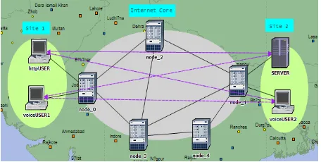
Fig 2: Network Components
The simulated network, as shown in Fig. 2, consists of three areas namely Site1, Internet Core and Site2. There are four end nodes out of which voiceUSER1 and httpUSER are located at Site1 and SERVER and voiceUSER2 are located at Site2. Internet Core consists of five routers (node_0, node_1, node_2, node_3, node_4). These routers are connected with point-to-point DS1 cable of data rate 1.54 Mbps. The end nodes are connected to Internet Core with point-to-point DS3 cable of data rate 44.736 Mbps. Simulation duration is set to 600 seconds.
3.2
Traffic Simulation
[image:2.595.61.276.551.698.2] [image:2.595.315.543.621.736.2]4.
NETWORK ANALYSIS WITH
RESPECT TO LINK UTILIZATION
We will first describe network with RIP and OSPF routing protocols. RIP is type of distance vector routing algorithm. Hop count is used as routing metric in RIP and routing path from source to destination can contain maximum of 15 hops. The restriction on number of hops poses difficulty in building bigger networks using RIP. RIP suffers from count to infinity problem. RIP chooses only single shortest path from source node to destination node out of available shortest paths. This leads to over utilization of chosen path and underutilization of other paths.
[image:3.595.322.536.71.485.2]OSPF is a type of interior gateway protocol. OSPF creates network topology map using link state information and it can detect link failures and converge on an alternate congestion free shortest path. OSPF on the other hand, uses both the available shortest paths and distributes the load over two chosen shortest paths, which leads to efficient link utilization. This is explained by simulating the RIP and OSPF networks using OPNET IT Guru.
Fig 4: Path Chosen by RIP
4.1
RIP and OSPF networks
[image:3.595.56.281.297.453.2]We have created separate scenario for each of the RIP and OSPF networks. The first scenario includes the network configured to work using RIP. Here all the nodes and interfaces are configured to RIP. Second scenario is same network with OSPF configured on all interfaces and nodes. In rest of the paper, <-> indicates bidirectional link between two nodes. -> and <- represents unidirectional link in forward and reverse direction respectively.
Fig 5: Path chosen by OSPF
Fig 6: node_0 <-> node_2 Link utilization in case of RIP
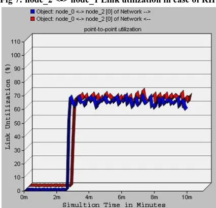
[image:3.595.321.534.495.700.2]Fig 7: node_2 <-> node_1 Link utilization in case of RIP
[image:3.595.55.282.561.693.2]Fig 9: node_2 <-> node_1 Link utilization in case of OSPF
Fig 10: node_3 <-> node_0 Link utilization in case of OSPF
For the same traffic intensity pattern as used in RIP, network configured with OSPF uses both available shortest paths to transmit the packets. OSPF chose links, node_0 <-> node_2 <-> node_1 and node_0 <-> node_3 <-> node_1 distributing the load on both paths. Fig. 8 and Fig. 9 shows that about 66% of the link node_0 <-> node_2 <-> node_1 is utilized. Fig. 10 and Fig. 11 shows that about 66% of the link node_0 <-> node_3 <-> node_1 is utilized. This shows that traffic load is distributed over two shortest paths resulting in efficient link utilization.
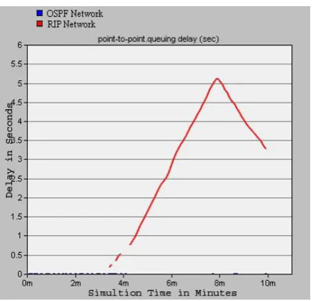
When link is over utilized packet queuing delay increases. Queuing delay at the paths chosen by RIP and OSPF is shown in Fig. 12 and Fig. 13. Fig. 12 and Fig. 13 indicate, RIP implemented network experiences maximum packet queuing delay for about, 7.5 seconds at node_0 -> node_2 and 5.1 seconds at node_0 -> node_2 respectively, whereas OSPF implemented network experiences no such delays. Thus OSPF performs better than RIP in terms link utilization.
[image:4.595.56.277.286.481.2] [image:4.595.316.543.498.716.2] [image:4.595.54.283.510.721.2]Fig 14: node_3 <-> node_2 is not utilized in both RIP and OSPF
Suppose incoming traffic gets doubled, then network working with OSPF fails in handling the incoming packets. Even though the shortest paths are congested, OSPF route the packets through those congested path only. OSPF does not take traffic engineering aspects to route the traffic through unutilized links. Even though other paths are free, traffic is transmitted through congested paths only. From the Fig. 14, it is clear that neither RIP nor OSPF routing protocols use the path node_3 <-> node_2 to transmit the packets.
4.2
MPLS Network
Now the third scenario where, MPLS enabled OSPF network is simulated by doubling the traffic i.e., Traffic (bits/sec) = 1,000,000 Mbps and Traffic (packets/sec) = 1000 (packets/sec) as shown in Fig. 15. In this network, label switched path is created indicated by red thick line from node_0 to node_1. Here, node_0 is the ingress router and node_1 is the egress router.
[image:5.595.55.281.86.308.2]MPLS Traffic Engineering efficiently distributes the incoming traffic over shortest path as well as other unutilized links also. This will ensure low queuing delay and low packet loss which is very essential for delay sensitive voice application.
[image:5.595.55.291.577.729.2]Fig 15: Label Switched Path in MPLS Network
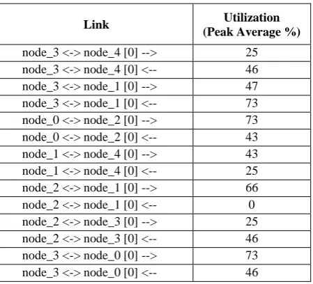
Table 1. Link Utilization in MPLS Network
Link Utilization
(Peak Average %)
node_3 <-> node_4 [0] --> 25 node_3 <-> node_4 [0] <-- 46 node_3 <-> node_1 [0] --> 47 node_3 <-> node_1 [0] <-- 73 node_0 <-> node_2 [0] --> 73 node_0 <-> node_2 [0] <-- 43 node_1 <-> node_4 [0] --> 43 node_1 <-> node_4 [0] <-- 25 node_2 <-> node_1 [0] --> 66 node_2 <-> node_1 [0] <-- 0 node_2 <-> node_3 [0] --> 25 node_2 <-> node_3 [0] <-- 46 node_3 <-> node_0 [0] --> 73 node_3 <-> node_0 [0] <-- 46
Table 2. Link Utilization Summary of RIP, OSPF and MPLS Networks
Routing Technologies
Links Utilized
Total Links
% Utilization
RIP 4 14 28.571~29%
OSPE 8 14 57.142~58%
MPLS TE 13 14 92.857~93%
From the above obtained results, efficiency of each of the routing technologies is summarized in the table 2.
After simulating the MPLS network for 600 seconds, we found MPLS has efficiently used many of the unutilized links shown in the table 1.
MPLS Traffic Engineering configuration has utilized 13 links out of 14 links in the core network which approximately matches to 93% of the total link utilization. This result is obtained by setting the Traffic intensity i.e., Traffic (bits/sec) = 1,000,000 and Traffic (packets/sec) = 1000 in the traffic demand between all the end nodes in the network. From this result it can be ensured that MPLS TE with OSPF protocol configured on all the nodes and interfaces, maximum link utilization is guaranteed.
5.
CONCLUSIONS
This paper explains poor link utilization in RIP and OSPF networks. It is seen that networks configured with RIP and OSPF routing techniques are not capable of handling the incoming traffic efficiently. When the network traffic increases, shortest path from source node to destination node is heavily congested and lead to loss of transmission data.
We have successfully simulated and shown the MPLS is capable of handling incoming traffic efficiently by distributing the traffic over unutilized links. This will ensure packets entering into MPLS core reach the destination with minimum queuing delay. MPLS-TE is most suitable for huge traffic volume.
6.
REFERENCES
[1] B. Forouzan, “Data Communications and Networking”, McGraw-Hill Higher Education, 4th ed., 2006, pp. 101-110.
[2] IEEE Communication magazine, September – 2006. [3] E. Rosen, A. Viswanathan and R. Callon,
“Multiprotocol Label Switching Architecture”, RFC 3031, Jan. 2001.
[4] J. L. Marzo, E. Calle, C. Scoglio, and T. Anjali, “QoS online routing and MPLS multilevel protection: a survey”, IEEE Communication Magazine, vol. 41, pp. 126-132, Oct. 2003.
[5] J. M. Chung, E. Marroun, H. Sandhu, and S. C. Kim, “VoIP over MPLS Networking Requirements”, in Proc. of IEEE International Conference on Networking, France, July. 2001.
[6] T. C. Hung, L. Q. Cuong and T. T. T. Mai, “A study on any transport over MPLS (AToM)”, in Proc. of International Conference on Advanced Communication Technology (ICACT), pp. 64-70, Feb. 2010.
[7] O. Gure, B. K. Boyaci and N. O. Unverdi, "Analysis of the service quality on MPLS networks", in Proc. of 5th European Conference on ECCSC, pp. 43-46, Nov. 2010. [8] Virk, A. P. Singh and R. Boutaba, “Economical
protection in MPLS networks”, Computer Communications, vol. 29, no. 3, pp. 402-408, 2006. [9] Shekhar Srivastava and Deep Medhi, “Traffic
Engineering of MPLS Backbone Networks in the Presence of Heterogeneous Streams”, International Journal of Computer and Telecommunications Networking, vol. 53, no. 15, Oct. 2009.
[10] N.Akar, M.A.Toksoz, “MPLS automatic bandwidth allocation via adaptive hysteresis”, Computer Networks: The International Journal of Computer and Telecommunications Networking, Volume 55, Issue 5, Pages 1181-1196, 1 April 2011.
[11] Cemal Kocak, Ismail Ertur and Huseyin Eki, “MPLS over ATM and IP over ATM methods for multimedia applications”, Computer Standards & Interfaces, vol. 31, no. 1, Jan. 2009, pp. 153–160.
[12] Larry L. Peterson and Bruce S. Davie, “Computer Networks – A Systems Approach”, 3rd ed., CA: The Morgan Kaufman Series in Networking, 2003, pp. 340-352.
[13] Bin Ali Z, Samad M, Hashim, H., “Performance comparison of video multicasting over Asynchronous Transfer Mode (ATM) & Multiprotocol Label Switching (MPLS) networks”, System Engineering and Technology (ICSET), IEEE International Conference on Digital Object Identifier: 10.1109/ICSEngT.2011.5993445, Page(s): 177 – 182, Publication Year: 2011
[14] T.J. Shi, G. Mohan, “An efficient traffic engineering approach based on flow distribution and splitting in MPLS networks”, Computer Communications, Volume 29, Issue 9, Pages 1284-1291, 31 May 2006.
[15] W. K. Lai, Z. C. Zhen, and C. D. Tsai., “Fast reroute with pre-established bypass tunnel in MPLS.”, Computer Communications, vol. 31, no.9 , 2008.
[16] K. G. Chun, J. Song, and S. S. Lee,” Review on the operation, administration and maintenance (OAM) of BcN”, Journal of communication and networks, vol. 8, no. 4, 2006.
[17] W. L. Huang, H. Y. Guo, “A Fault-Tolerant Strategy for Multicasting in MPLS Networks”, Proc. International Conference on Computer Engineering and Technology, IEEE Press, January 2009.
[18] C. L. Chen, “Enhancing MPLS Protection Method with Adaptive Segment Repair”, IEICE Transaction on Communications, vol. E92-B, no. 10, 2009.
[19] S. Alouneh, A. Agarwal, A. Ennouaary, “A novel path protection scheme for MPLS networks using multi-path routing”, Computer Networks: The International Journal of Computer and Telecommunications Networking, vol. 53, no. 9, 2009.
[20] A. Ghanwani, “Traffic Engineering Standards in IP Networks Using MPLS”, in IEEE Communications Magazine, vol. 37, no. 12, 1999, pp. 49- 53.