Energy Consumption Estimation in Cluster based
Underwater Wireless Sensor Networks Using M/M/1
Queuing Model
Manijeh Keshtgary
Department of Computer Engineering and InformationTechnology Shiraz University of
Technology Shiraz, Iran
Reza Mohammadi
Department of Computer Engineering and InformationTechnology Shiraz University of
Technology Shiraz, Iran
Mohammad Mahmoudi
Department of Computer Engineering and InformationTechnology Shiraz University of
Technology Shiraz, Iran
Mohammad Reza
Mansouri
Department of Computer Engineering and InformationTechnology Shiraz University of
Technology Shiraz, Iran
ABSTRACT
Underwater Wireless Sensor Networks (UWSN) has attracted significant attention recently. One of the most important issues in these networks is the energy constraint. Battery power in UWSN is limited and usually batteries cannot be easily recharged or changed. Therefore energy saving in this type of networks is vital. Network life time can be estimated by estimating energy consumption of nodes. In this paper, first we propose an analytical model for energy consumption estimation in cluster based underwater wireless sensor networks using M/M/1 queuing model. To the best of our knowledge, this is the first analytical model that represents the underwater cluster head’s behavior based on M/M/1 queuing model. We can use this model to investigate the network performance in terms of average energy consumption. Then, we propose an analytical scheme to reduce energy consumption of cluster head nodes by reducing number of transitions between the idle and active states of cluster head nodes based on the number of data packets in the queue. Our analytical model is suitable for delay-tolerant aquatic applications. We validate our analytical model using simulations.
General Terms
Energy consumption in underwater wireless sensor networks.
Keywords
Underwater Wireless Sensor Networks, M/M/1 queuing model, Energy Consumption Model.
1.
INTRODUCTION
Underwater Wireless Sensor Networks (UWSN) consists of a number of spatially distributed underwater sensor nodes that communicate with each other using acoustic signal. UWSN are suitable for aquatic applications such as distributed tactical surveillance, disaster prevention, mine reconnaissance, environmental monitoring and water quality monitoring [1, 2, 3, 4, 5]. There are many differences between the underwater environment and the open ground environment. The main restrictions of the underwater sensor networks are the salinity, temperature, pressure, humidity and changes in underwater environment. Since electromagnetic signal has high attenuation in water environment; it isn’t suitable for underwater communication [6]. Instead UWSN use acoustic signal for transmitting data. Acoustic signals have extremely limited bandwidth, travel slowly (approximately1500 m/s)
and have high bit error rate due to the noise, refraction and multipath interference [7]. Because of corrosion and fouling in underwater environment, underwater sensors may fail. In UWSN, power management is very important issue because of limited battery power and also batteries cannot be recharged or changed when depleted [8]. In this paper, we propose an analytical model using M/M/1 queuing model to estimate energy consumption of each cluster head. For more energy saving, we proposed an analytical scheme to reduce number of transitions between the idle and active states.
The rest of this paper is organized as follows. In section 2, we discuss some of the energy conservation techniques in wireless sensor networks. We discuss clustered network architecture and system model in section 3. In section 4, we present the proposed analytical model to estimate the energy consumption in clustered based UWSN. In section 5, we present the simulation results which validate the proposed model. In section 6, we propose an analytical scheme to reduce energy consumption of cluster head nodes by reducing number of transitions between the idle and active states of cluster head nodes based on the number of data packets in the queue. We conclude the paper in section 7.
2.
RELATED WORK
In this section, we review some related work on energy conservation techniques in wireless sensor networks. In most UWSN, network lifetime depends on battery lifetime. Therefore by reducing energy consumption, network lifetime can be prolonged. In many cluster based UWSN, cluster head nodes consumes more energy than ordinary sensor nodes. Therefore estimating energy consumption for each cluster head can help to estimate the network lifetime. R. Maheswar and R. Jayaparvathy [9] developed an analytical model of a cluster based sensor network using M/G/1 queuing model. The authors have analyzed the system performance in terms of energy consumption and the mean delay.
and R. Jayaparvathy [11, 12] introduce an energy minimization technique using BUSY and IDLE states where the energy consumed is minimized based on queue threshold using M/M/1 queuing model. An analytical model also presented in [13] to analyze the system performance in terms of power consumption, data delivery delay and network capacity against the sensor dynamics states in on/off modes.
3.
CLUSTERED NETWORK
ARCHITECTURE AND SYSTEM
MODEL
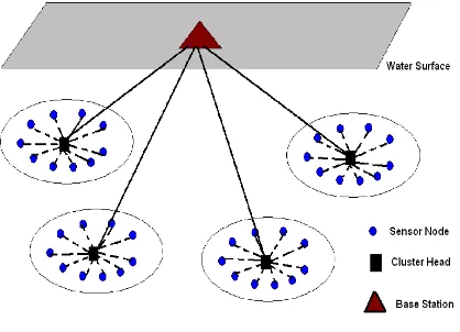
[image:2.595.58.267.364.515.2]In this section, we present network architecture and system model. To accomplish energy consumption estimation, we consider clustered network architecture. In this network, we have three different types of nodes, cluster head, base station and sensor nodes, as shown in figure 1. In this network architecture, the whole network is divided into several clusters. In each cluster, ordinary sensor nodes will mainly be used for the sensing task. The ordinary sensor nodes are assumed to have less battery energy than cluster head nodes. The ordinary sensor nodes are cheap sensor nodes which cannot directly communicate with the base station. Typically, the ordinary sensor nodes can only connect to its one hop cluster head. Cluster heads are powerful nodes that can gather data from ordinary sensor nodes and forward it to the base station.
Figure 1- Clustered Network Architecture
In our UWSN model, the following assumptions are made:
All ordinary sensor nodes are identical All cluster head nodes are identical No channel contention
Each ordinary node sends packets to cluster head independently and identically
The arrival of data packets to cluster head nodes is assumed to follow a Poisson process with mean arrival rate (λ)
Packets are delivered from ordinary sensor nodes to cluster head nodes in each cluster
Packets are delivered from cluster head nodes to the base station and assumed to follow a Poisson process with mean service time (1/μ)
The buffer capacity of the cluster head node is infinite
Each cluster has only one cluster head
Number of ordinary sensor nodes in each cluster are the same
Since the focus of this work is to estimate the energy consumption of cluster head nodes in UWSN, we analyze the behavior of a single cluster head node.
4.
ENERGY CONSUMPTION
ANALYTICAL MODEL
For our analytical model, we use following notations:
λ: mean arrival rate per cluster head μ: mean service rate in cluster head
ρ: utilization of the cluster head
p0: probability that the cluster head is in idle state
ETX: energy consumption for sending one data packet
EIdle: energy consumption in idle state
N: mean number of packets in cluster head per unit time
PW: average energy consumption of a cluster head per unit time
M: number of clusters
QM: total energy consumption of M cluster heads per unit time
The steady state balance equations obtained for the analytical model according to the M/M/1 queuing model which are given by equations (1) to (6).
Based on M/M/1 queuing model the mean number of packets in the cluster head (N) is determined as:
𝑁 = 𝜌
1−𝜌 (1) Where
𝜌 =𝜆
𝜇 (2)
And the probability that the cluster head is in idle state is determined as:
P0=1-ρ (3)
Energy required for sending a data packet can be determined as:
𝐸𝑇𝑋=𝐵𝑎𝑛𝑑 𝑊𝑖𝑑𝑡 ℎ𝑃𝑎𝑐𝑘𝑒𝑡 𝑆𝑖𝑧𝑒 × 𝑇𝑟𝑎𝑛𝑚𝑖𝑠𝑠𝑖𝑜𝑛 𝑃𝑜𝑤𝑒𝑟 (4)
Now, the average energy consumption of a cluster head can be expressed as:
PW=N.ETX+P0.EIdle=NETX + (1-ρ)EIdle (5)
For example, consider mean arrival rate per cluster head of 0.1 (λ=0.1), mean service rate in cluster head of 0.5 (μ= 0.5), bandwidth of 10 kbps, packet size of 1600 bytes, EIdle of 0.01 and transmission power of 0.2 joule in a cluster based underwater wireless sensor network, then we have following values:
The utilization of a cluster head (ρ) is :
𝜌 =𝜆𝜇=0.1
0.5= 0.2
𝑁 =1−𝜌𝜌 =0.2
0.8= 0.25
The probability that the cluster head is in idle state (P0) is:
P0=1-ρ=1-0.2=0.8
The energy required for sending a data packet is:
Energy required for sending a data packet (𝐸𝑇𝑋) can be determined as:
𝐸𝑇𝑋=𝐵𝑎𝑛𝑑 𝑊𝑖𝑑𝑡 ℎ𝑃𝑎𝑐𝑘𝑒𝑡 𝑆𝑖𝑧𝑒 × 𝑇𝑟𝑎𝑛𝑚𝑖𝑠𝑠𝑖𝑜𝑛 𝑃𝑜𝑤𝑒𝑟 (4)
Now, the average energy consumption of a cluster head (PW) can be expressed as:
PW=N.ETX+P0.EIdle=NETX + (1-ρ)EIdle (5)
For example, consider mean arrival rate per cluster head of 0.1 (λ=0.1), mean service rate in cluster head of 0.5 (μ= 0.5), bandwidth of 10 kbps, packet size of 1600 bytes, EIdle of 0.01 and transmission power of 0.2 joule in a cluster based underwater wireless sensor network, then we have following values:
The utilization of a cluster head is :
𝜌 =𝜇𝜆=0.1
0.5= 0.2
The mean number of packets in cluster head is:
𝑁 =1−𝜌𝜌 =0.2
0.8= 0.25
The probability that the cluster head is in idle state is:
P0=1-ρ=1-0.2=0.8
The energy required for sending a data packet is:
𝐸𝑇𝑋=𝐵𝑎𝑛𝑑 𝑊𝑖𝑑𝑡 ℎ𝑃𝑎𝑐𝑘𝑒𝑡 𝑆𝑖𝑧𝑒 × 𝑇𝑟𝑎𝑛𝑚𝑖𝑠𝑠𝑖𝑜𝑛 𝑃𝑜𝑤𝑒𝑟 = 1600∗810000 ×
0.2 = 0.256
And the average energy consumption of a cluster head per unit time is:
PW=N.ETX+P0.EIdle=NETX + (1-ρ)EIdle=0.25*0.2+0.8*0.01=0.058
Also the average energy consumption of M cluster heads can be expressed as:
QM=M.PW (6)
5.
MODEL VALIDATION USING
SIMULATIONS
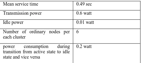
Now, we use simulations to validate our analytical model. We use aqua-sim, an NS2 simulator for underwater sensor networks [14]. Simulation parameters used for the simulation model are shown in Table 1.
Table 1- network and energy consumption specifications
Mean service time 0.49 sec
Transmission power 0.6 watt
Idle power 0.01 watt
Number of ordinary nodes per each cluster
6
power consumption during transition from active state to idle state and vice versa
0.2 watt
Packet size 400 byte
Band width 10 kbps
Mean arrival rate per cluster head(λ)
0.01 to 0.1 packet per second
Simulation time 1000 seconds
Simulations results are obtained for various scenarios by changing the mean arrival rate of cluster head and also changing the number of cluster heads. We measure the average energy consumption of a cluster head and the average energy consumption of M cluster heads. The simulations were performed for 10 runs and a confidence interval of 99% was obtained.
From figure 2, it is inferred that the average energy consumption for a cluster head increases as mean arrival rate increases because the number of packets that arrive to the cluster head increases. Also figure 2 shows that our analytical model for average energy consumption per cluster head approximately matches with simulation results. Our analytical model matches 99.91% with simulation result.
[image:3.595.319.545.384.512.2]Figure 3 shows average energy consumption for various numbers of cluster heads and mean arrival rate of 0.01 and 0.1 packet per second. As shown in figure 3, the average energy consumption increases linearly as the number of cluster heads increases. Figure 3 shows that our analytical model for average energy consumption in a cluster based UWAN matches with simulation result for large number of clusters.
[image:3.595.49.286.648.755.2]Figure 2- Mean arrival rate vs. energy consumption per a cluster head
6.
ANALYTICAL MODEL TO REDUCE
NUMBER OF TRANSITIONS
Transitions from active state to idle state and vice versa consume most of the energy in UWSN. If we reduce the number of switches between these states, we can reduce energy consumption. If cluster head stays in idle state until receive B packets and then switches to the active state, it can reduce the number of switches between the states. To calculate the energy consumption of transitions in a single cluster head, we define the following parameters:
T: total time
ETransition: energy consumption during transition from active state to idle state and vice versa
NTransition: number of transitions during T seconds
PTotal-Transitions: total energy consumption for transitions during T seconds per cluster head
B: buffer size of cluster head
λ: mean arrival rate for each cluster head
The steady state balance equations are given by equations (7,8):
The number of transitions during T seconds can be expressed as;
𝑁𝑇𝑟𝑎𝑛𝑠𝑖𝑡𝑖𝑜𝑛 =𝑇×𝜆𝐵 (7)
Now, the total energy consumption of a cluster head can be expressed as:
𝑃Total −Transitions = 𝑁𝑇𝑟𝑎𝑛𝑠𝑖𝑡𝑖𝑜𝑛 × 𝐸𝑇𝑟𝑎𝑛𝑠𝑖𝑡𝑖𝑜𝑛 (8)
For example, by assuming λ=0.1, T=1000, 𝐸𝑇𝑟𝑎𝑛𝑠𝑖𝑡𝑖𝑜𝑛 = 0.2 and buffer size=5 in a cluster based underwater wireless sensor network, then we have the following :
The number of transitions during 1000 seconds is:
𝑁𝑇𝑟𝑎𝑛𝑠𝑖𝑡𝑖𝑜𝑛 =𝑇×𝜆𝐵 =1000∗0.15 = 20
The total energy consumption of a cluster head is:
𝑃Total −Transitions = 𝑁𝑇𝑟𝑎𝑛𝑠𝑖𝑡𝑖𝑜𝑛 × 𝐸𝑇𝑟𝑎𝑛𝑠𝑖𝑡𝑖 𝑜𝑛= 20 ∗ 0.2 = 4 𝑗𝑜𝑢𝑙𝑒
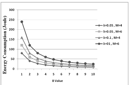
Our analytical model is suitable for delay-tolerant aquatic applications such as mine reconnaissance, undersea explorations, environmental monitoring, and ocean sampling. In such applications energy saving is an important issue and end to end delay isn’t much important. We use equation (8) with various mean arrival rate and various B value for a cluster head with the network and power consumption parameters of Table 1. Figure 4 shows the result for T=1000 seconds. Form this figure, we observe that energy consumption decreases as the B value increases. Figure 4, also shows that energy consumption decreases as the mean arrival rate decreases. From figure 4 we can conclude that, there are small differences between energy consumption for transitions for various mean arrival rate for B>6.
We also use equation (8) with various mean arrival rate and various B value for 4 and 6 cluster heads. Figure 5 shows the result for T=1000 seconds. From figure 5. it is inferred that the energy consumption for transitions decreases as mean
[image:4.595.317.549.126.292.2]are small differences between energy consumption for transitions for various mean arrival rate and various number of cluster heads. From figure 5 we observe that energy consumption for transitions can be reduced by reducing the number of transitions.
Figure 4- B value vs. energy consumption for transitions during T=1000 seconds per cluster head
Figure 5 – B value vs. energy consumption for transitions during T=1000 seconds for various number of cluster
heads
7.
CONCLUSIONS
In this paper, we proposed a new analytical model to estimate the energy consumption in cluster based UWSN using M/M/1 queuing model. We validate this model using simulations. Transitions between idle state and active state in UWSNs consume more energy. For this purpose we have developed an analytical model for energy saving by reducing the number of transitions between idle sate and active state. Our analytical model is suitable for delay-tolerant aquatic applications. The results of our analytical model show that reducing the number of transitions has a significant impact on energy saving.
8.
REFERENCES
[1] M. Keshtgari, R. Javidan and R. Mohammadi. March 2012. Comparative Performance Evaluation of MAC Layer Protocols for Underwater Wireless Sensor Networks, Canadian Center of Science and Education, Vol. 6, No. 3;
[image:4.595.316.544.331.480.2]Acoustic Sensor Networks, ACM SIGBED Review, Vol. 1(1).
[3] J.-H. Cui, J. Kong, M. Gerla, and S. Zhou.. May 2006. Challenges:Building Scalable Mobile Underwater Wireless Sensor Networks for Aquatic Applications. Special Issue of IEEE Network on Wireless Sensor Networking.
[4] J. Heidemann, W. Ye, J. Wills, A. Syed, and Y. Li . April 2006. Research Challenges and Applications for Underwater Sensor Networking. In IEEE Wireless Communications and Networking Conference, Las Vegas, Nevada, USA.
[5] G. G. Xie and J. Gibson.December 2000. A Networking Protocol for Underwater Acoustic Networks. In Technical Report TR-CS-00-02, Department of Computer Science, Naval Postgraduate School.
[6] J. A. Catipovic,1990. Performance limitations in underwater acoustic telemetry , IEEE J. Oceanic Eng., pp.205-216.
[7] F. Yunus, S Ariffin and Y. Zahedi, 2010. A Survey of Existing Medium Access Control (MAC) for Underwater Wireless Sensor Network (UWSN). Fourth Asia International Conference on Mathematical/Analytical Modelling and Computer Simulation, pp. 544-549.
[8] Manjula, R., & Manvi, S. 2011. Issues in underwater acoustic sensor networks. International Journal of
Computer and Electrical Engineering.
[9] R. Maheswar and R. Jayaparvathy . 2011. Performance Analysis of Cluster Based Sensor Networks using N-Policy M/G/1 Queueing Model. European Journal of Scientific Research , EuroJournals Publishing, Inc.
[10]J. Carle and D. Simplot-Ryl, Feb. 2004 . Energy-efficient area monitoring for sensor networks. IEEE Computer, vol. 37, no. 2, pp. 40–46.
[11]R. Jayaparvathy and R. Maheswar, May 2010. Power Optimization Method for Heterogeneous Sensor Network with Finite Buffer Capacity, IJRTET, Vol. 3, No. 3, pp. 218-220.
[12]R. Jayaparvathy and R. Maheswar. August 2010. Power Control Algorithm for Wireless Sensor Networks using N-Policy M/M/1 Queueing Model . IJCSE Vol. 02, No. 07, pp. 2378-2382.
[13]C. F. Chiasserini and M. Garetto. 2006. An analytical model for wireless sensor networks with sleeping nodes,” IEEE Trans. Mobile Computing, vol. 5, no. 12, pp. 1706–1718 .