Self Healing MIMO Transreceiver Module On-Chip
Manoj Kumar Das
Research Scholar, ECE department, JNTU Ananathpur
D Raja Veerappa
Professor and Head,Dept. of ECE, Loyla Institute of technology, Chennai
ABSTRACT
In this study channel estimation and error recovery schemes to support self-healing Multi Input Multi Output transmitter and receiver architecture is proposed. The paper can coexist with existing Automatic modulation Identification hardware module. This technique is used for interference identification and source identification of received signal. The Decision theoretic approach uses the likelihood function where probabilistic and hypothesis-testing arguments to formulate the recognition problem at the output of the channel and accordingly classification are performed. The merits of the proposed approach are its lesser computational complexity, ease in implementation and robustness to model mismatch.
Keywords
Self healing, MIMO, Module on-chip,
1. INTRODUCTION
MIMOC is a dynamic and flexible network architecture that protects existing investments while future proofing the network. With MIMOC, today’s static network can evolve into an extensible service delivery platform capable of responding rapidly to changing business, end-user, and market needs.
2.
MIMO
NETWORKING
ARCHITECTURE
Traditional network architectures are ill suited to meet the requirements of today’s enterprises, carriers, and end users. MIMO-on-Chip (MIMOC) is transforming networking architecture. MIMOC is currently being rolled out in a variety of networking devices and software, delivering substantial benefits to both enterprises and carriers, including,
(i) centralized management and control of networking devices from multiple vendors, improved automation and management by using common APIs to abstract the underlying networking details from the orchestration and provisioning systems and applications,
(ii) rapid innovation through the ability to deliver new network capabilities and services without the need to configure individual devices or wait for vendor releases,
(iii) programmability by operators, enterprises, independent software vendors, and users (not just equipment manufacturers) using common programming environments, which gives all parties new opportunities to drive revenue and differentiation,
(iv) increased network reliability and security as a result of centralized and automated management of network devices, uniform policy enforcement, and fewer configuration errors,
(v) more granular network control with the ability to apply comprehensive and wide-ranging policies at the session, user, device, and application levels and
(vi) better end-user experience as applications exploit centralized network state information to seamlessly adapt network behavior to user needs.
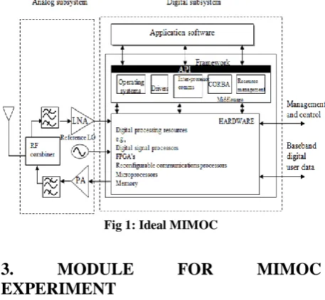
[image:1.595.315.544.357.568.2]In the MIMOC architecture, the control and data planes are decoupled, network intelligence and state are logically centralized, and the underlying network infrastructure was abstract from the applications. As a result, enterprises and carriers gain unprecedented programmability, automation, and network control, enabling them to build highly scalable, flexible networks that readily adapt to changing business needs. An example of an Ideal MIMOC block diagram is shown in Figure 1.
Fig 1: Ideal MIMOC
3.
MODULE
FOR
MIMOC
EXPERIMENT
and one PWM timer, as well as standard and advanced communication interfaces: up to two I2Cs and SPIs, three
[image:2.595.56.285.154.328.2]USARTs, an USB and a CAN. The devices operate from a 2.0 to 3.6 V power supply. They are available in both the –40 to +85°C temperature range and the –40 to +105 °C extended temperature range. A comprehensive set of power-saving mode allows the design of low-power applications.
Fig 2: Circuit module of STM32F103RB
4. DESIGN OF TRANSMITTER AND
RECEIVER
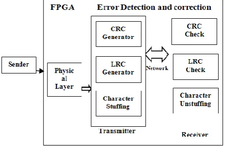
The transmitter acts under the physical layer of OSI model. It enhances the error detection and control mechanisms using LRC. It reads the input frames given by the user and converts into a framing sequence. The Arm processor is configured to act as a error detection and correction unit for the physical layer [6]. The hardware (Figure 3) functions as a self-healing physical layer implementation in future embedded web server. The Receiver receives the information, detects and corrects errors and retransmits it to the side-by-side configured server system. The hardware implementation of the error recovery block on the ARM processor along with the data recovered output is shown in appendix -1.
Fig 3: Architecture of error detection using FPGA in Physical layer
The receiver takes the input and gives an acknowledgement to the received data before the next sequence is transmitted. During any error, an out of sequence error message is displayed.
5. PERFORMANCE OF LONGITUDINAL
REDUNDANCY CHECK
A longitudinal redundancy check (LRC) is a form of redundancy check that is applied independently to each of a parallel group of bit streams. The data is divided into transmission blocks, to which the additional check data is added [10]. While simple longitudinal parity can only detect errors, it can be combined with additional error control coding schemes, such as a transverse redundancy check, to correct the errors [13]. The architecture in Figure 4 represents the LRC generation method for the binary data using both 1’s and two’s complement.
Fig 4:Schematic diagrams for LRC generation mechanism
5.1 Implementation of LRC
LRC = Calc_LRC(data, (int)strlen(data)); {printf("LRC is %u",LRC); getchar();
return; }
unsigned char Calc_Crc(unsigned char *Arr, int count) {
unsigned char LRC = 0x00; int index;
for (index = 0; index < count; index++) {
LRC = (byte)(Arr[index] + LRC); }
LRC = (byte)(0xFF - LRC); // 1's complement
LRC = (byte)(LRC+1); // 2's complements return (LRC);
}
6. CHANNEL ESTIMATOR
[image:2.595.318.547.219.365.2] [image:2.595.55.284.514.662.2]s1 = 0.8*sin(2*pi*n/10)+0.25*cos(2*pi*n/25); … (1) … (1) s2 = randn(1,100); … (2)
Fig 5(a): Comparison of the desired and actual channel output of the equalized channel to the training signal
x-axis – time samples in sec y-axis – amplitude in V
Fig 5(b): Comparison of the desired and actual channel output of the equalized channel to the test signal s1 (n)
x-axis – time samples in sec y-axis – amplitude in V
Fig 5(c): Comparison of the desired and actual channel output of the equalized channel to the test signal s2 (n)
x-axis – time samples in sec y-axis – amplitude in V
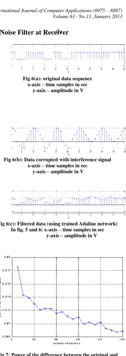
7. Noise Filter at Receiver
Fig 6(a): original data sequence x-axis – time samples in sec
y-axis – amplitude in V
Fig 6(b): Data corrupted with interference signal x-axis – time samples in sec
y-axis – amplitude in V
Fig 6(c): Filtered data (using trained Adaline network) In fig. 5 and 6: x-axis – time samples in sec
[image:3.595.328.548.23.642.2]y-axis – amplitude in V
Fig 7: Power of the difference between the original and filtered signal as a function of number of Adaline neurons
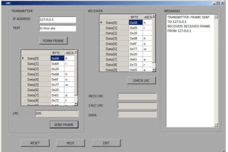
[image:3.595.79.285.70.266.2] [image:3.595.82.289.341.493.2] [image:3.595.325.548.469.622.2]Fig 8 (a): view of LRC Transmitter message
Fig 8(b): LRC matching check at receiver
Table1. Performance Metrics
Performance Metrics Distance
(M)
5 10 15 20 25 30 35 40 45 50 55 60 65 70 75 80 85 90 95 100
Loss (%) 4 4.5 4.9 6.5 9.5 4.7 5.3 1.9 1.8 2.3 2.2 2.4 3.4 4.0 1.1 1.2 1.3 1.8 1.9 2.1
Utilization (%)
65 65 64 63 63 39 38 17 17 17 16 16 16 16 9 9 9 9 9 9
Tx Time(S)
1.7 1.7 1.7 1.7 1.7 2.2 2.2 5.9 5.9 5.9 5.9 5.9 5.9 5.9 11.8 11.8 11.8 11.8 11.8 11.8
Note:
Modulation 1 @ 10 Mbps Data Rate
Modulation 2 @ 5 Mbps Data Rate
Modulation 3 @ 2Mbps Data Rate
Modulation 4 @ 1 Mbps Data Rate
9. CONCLUSION
The approach described in this work auto-generates self-validating models from partial specification of the system there by providing annotations in the implementation itself. The proposed approach thus makes it easier to maintain correspondence between the error detection schemes, which is difficult to achieve in manual verification methods. It also brings the advantages of explicit-state model checking to the verification and error correction in OSI network applications. To mitigate the errors introduced due to the interference automatic error detection and correction schemes for physical layer models is presented. The reconfigurable architecture enables the addition of new features, allows rapid implementation of new standards and protocols on an as-needed basis and protects the investment in computing hardware. It functions as a programmable hardware with higher performance and allows the flexibility of a software based solution while retaining the execution speed of a more traditional hardware based approach.
10. ACKNOWLEDGEMENT
The authors heartly thank M/s. MicroLogic Systems, Chennai-600017, for the infrastructure to carry out this work successfully.
REFERENCES
[1] W. Yu, W. Rhee, S. Boyd, and J. M. Cioffi. Iterative water-filling for Gaussian vector multiple access channels. IEEE Transactions on Information Theory, vol.50, no.1: pp145– 152, January 2004.
[2] A. Soysal and S. Ulukus. Optimum power allocation for single-user MIMO and multi-user MIMO-MAC with partial CSI. IEEE Journal on Selected Areas in Communications, vol.25, no.7: pp 1402–1412, September 2007.
[3] Zentner. R, Nagy R, Zentner E, Elliptical Single- bounce Model for MIMO Channel Simulations", COST273, Germany, 2004.
[4] Gesbert, David; Akhtar, Jabran. Breaking the barriers of Shannon's capacity: An overview of MIMO wireless system. Telektronikk pp 1-9,2002.
[5] M.I. Rahman, E. de Carvalho & R. Prasad, “Impact of MIMO Co-Channel Interference,” in proc. 18th IEEE PIMRC’07, Athens, Greece, pp 1-5, September 2007.
[6] M. Simon and V. Vilnrotter, “Alamouti-type space-time coding for free space optical communication with direct detection,” IEEE Trans. On Wireless Communications, vol. 4, no. 1, pp. 35–39, 2005.
[7] J. Z. Ying and K. B. Letaief, "Adaptive resource allocation for multi-access MIMO/OFDM systems with matched filtering, " IEEE Trans. Comm., vol. 53, no. 11, pp. 1810- 1816, Nov. 2005.
[8] J. Kim and J. M. Cioffi, "Spatial Multi-user Access with Antenna Diversity using Singular Value Decomposition," Proc. IEEE Int'l. Conf Communications, '00, pp. 1253-1257, Jun. 2000.
[image:4.595.55.283.72.224.2][10] Moon, H. and C. Cox, “Efficient power allocation for coded OFDM systems,” IEEE Transactions on communications. Vol.57, no. 4,Aprill 2009
[11] Alard, M. B., Le Floch, , and C. Berrou, , “Coded orthogonal frequency multiplex,” Proc. IEEE, vol. 83, no. 6, pp. 982-996,June 1995
[12] Keller, T. and L. Hanzo, “Sub-band adaptive pre-equalized OFDM transmission,” in Proc. IEEE VTC, Amsterdam, Netherlands, Sept. 1999
[13] Park, C. S and K. B. Lee, “Transmit power allocation for BER performance improvement in multicarrier systems,” IEEE Trans. Commn. vol. 52, no. 10, pp. 1658-1663 Oct. 2004.
[14] Sakai, H., W. Bocquet, and K. Hayashi, “Frequency domain power adaptation scheme for coded OFDM transmissions,” in Proc. 13th European Wireless Conf., Paris, France. Apr. 2007 [15] Taricco, G., G. Caire, and E. Biglieri, “Bit-interleaved
coded modulation,” IEEE Trans. Inform. Theory, vol. 44, no. 3, pp.927-946 , May 1998.
AUTHOR’S PROFILE
Manoj kumar Das is a research scholar in ECE department from JNTU, Ananathpur, India.He has passed bachelor degree in Electronics and communication Engineering from Institution of engineers(India) in 1996. He has received M.Tech. degree in Electronics and communication Engineering from Pondicherry engineering college in 2000.
His areas of interest are Wireless Communication, DSP, Electromagnetic field and Microwave Engineering.
Dr. D. Rajaveerappa received BE from NIT, Tiruchirappalli in 1985 and M.Tech. from IIT, Madras in 1988. He has earned his Ph.D. from IISC, Bangalore in 2004. Presently he is a professor, department of ECE, ,Loyla Institute of technology, Chennai. His area of interest are wireless communication, signal processing and computer network.
Recovered Data