Design of hoppers using spreadsheet
C.O.C. Oko, E.O. Diemuodeke, I.S. Akilande
Department of Mechanical Engineering, Faculty of Engineering, University of Port Harcourt,
Port Harcourt, Nigeria
Abstract
Oko C.O.C., Diemuodeke E.O., Akilande I.S., 2010. Design of hoppers using spreadsheet. Res. Agr. Eng., 56: 53–58.
This paper presents a spreadsheet add-in for the design of mass flow conical and wedge hoppers. The Jenike’s hopper design charts for mass flow were curve fitted. The relationships obtained were used together with other relevant expres-sions to develop an add-in tool for the determination of the pertinent hopper design parameters (exit size, mass flow rate, semi-included angle, flow factor, and critical applied stress) in the Microsoft Excel environment. The add-in was tested with experimental data, and results obtained were in agreement with those obtained in the literature.
Keywords: hopper design; curve fitting; Jenike’s hopper design charts; MS Excel add-in
The need for effective handling of large quantity and variety of food materials produced industrially in powdered form necessitated the introduction of hop-pers for material handling. The complexity surround-ing hopper design is mostly due to the material flow ability, which depends principally on the mechanical behaviour of the stored material, semi-included an-gle, flow factor and the critical applied stress.
Powder properties significantly affect powder behaviour during storage, handling and process-ing (Peleg 1978; Rhodes 1990; Knowlton 1994; Stasiak, Molenda 2004). Therefore, powder flow property measurement is very important in han-dling and processing operations, such as flow from hoppers, transportation, mixing, compression, and packaging. Jenike (1994) identified the properties that affect material flow in storage vessels and their measurement techniques. He also applied measured property data to two-dimensional stress analysis to develop charts and a mathematical model for de-termining the minimum hopper angle and hopper opening exit size for material flow from conical and wedge-shaped hoppers (Fig. 1). The geometrical characteristics of the hopper affect the rate of flow of the material out of the hopper (Bidgwater, Scott
1983; Griffith 1991; Holdich 2002; Fitzpatrick et al. 2004). Jenike and Johanson (1969) explained the various ways that grains might move during emptying, and the flow patterns that are developed.
The trend in contemporary engineering prac-tice is the application of computer technology to design processes that have well established proce-dure such as the Jenike’s hopper design proceproce-dure. Spreadsheet solution of such design problems is relatively simple and straightforward, especially when the solution algorithm can be appended to the spreadsheet. The MS Excel environment allows the appendage of computer programmes written in Visual Basic for Applications (VBA), called MS Ex-cel add-in tools (Liengme 2000).
The purpose of this paper is, therefore, to design the conical and wedge hoppers more efficiently and automatically by replacing the Jenike’s charts with al-gebraic polynomials, and applying relevant
relation-ships, including the Lagrange interpolation scheme, to determine the relevant design parameters using the MS Excel spreadsheet with an add-in.
MAtErIAl AnD MEthODS
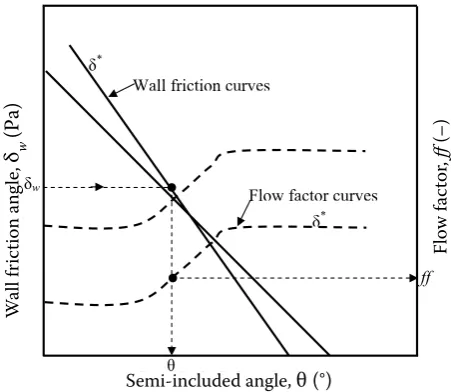
The MS Excel curve fitting tool is a popular tool for automatic curve fitting by computer (Liengme 2000; Mustafa 2000). It was used to curve fit the Jenike’s charts. The correlations for the semi-in-cluded angle (θi) and flow factor ( ffi) as functions of the wall friction angle (δw) at specified effective angle of internal friction (δi) are listed in Tables 1 and 2, respectively.
d
T T
l
(a)Conical hopper (b) Symmetrical slot or wedge hopper
[image:2.595.63.351.80.276.2]w
Fig. 1. Conical and wedge hoppers showing the semi-included angle (θ), diameter (d), slot width (w), and length (l)
[image:2.595.63.289.515.711.2](a) (b)
Fig. 2. An illustration of the Jenike’s hopper design chart for the determination of the wall friction angle (δw) and flow factor ( ff )
W
al
l f
ri
ct
io
n
an
gl
e,
įw
(P
a)
Fl
ow
fa
ct
or
,
ff
(-)
Semi-included angle, ș (o)
Wall friction curves
Flow factor curves į*
į*
ș įw
ff
Flow f
ac
tor
,
ff
(–)
Semi-included angle, θ (°)
W
all f
ric
tion ang
le,
δ w
(P
a)
Compacting stress, ıc (Pa)
ıacr
1/ff
MFF
U
nc
on
fin
ed
y
ie
ld
s
tr
es
s,
ıa
(Pa)
Fig. 3. Graphical solution for the critical applied stress (σacr ), which depends on the flow factor ( ff ) and mass flow function (MFF)
Compacting stress, σc(Pa)
U
nc
onfine
d y
ie
ld str
ess
,
σ a
(P
[image:2.595.303.532.525.704.2]The wall friction angle (δw) and effective angle of internal friction (δ) are obtained experimentally. To obtain the semi-included angle (θ) and flow factor ( ff )we substitute δw into the correlations in Tables 1 and 2, and interpolate for θ and ff with δ serving as the interpolation point. Thus, using the Lan-grage polynomial interpolation scheme (Chapra, Canale 2002; Oko 2008), we get the following nu-merical schemes for the semi-included angle and flow factor as functions of the wall friction angle and effective angle of internal friction:
3 3
0 0
( , ) j
w i
i j i j
j iz i
§ G G ·
¨ ¸
T G G T ¨ ¸
G G
¨ ¸
© ¹
¦
(1)and
3 3
0 0
( , ) j
w i
i j i j
j i i
ff ff
z
§ G G ·
¨ ¸
G G ¨ ¸
G G
¨ ¸
© ¹
¦
(2)Experimentally, one obtains the unconfined yield stresses or applied stresses (σai) that correspond to some compacting stresses (σci); where i = 0, 1, …, n–1 are the numbers of experiments conducted. The critical applied stress, which corresponds to the unconfined yield stress at the point of the intersec-tion of the MFF and 1/ff curves (Fig. 3), is deter-mined by the following expression:
¨ıai = ıai – ci ff
V
;i = 0, 1,…,n–1 (3)
where:
∆σai – difference between MFF and 1/ff at the data points; the point at which ∆σa = 0 yields the desired crit-ical applied stress, σc = σci
By using the Lagrange polynomial interpolation as follows:
V
c(¨ıa= 0) =1 1
0 0( )
n n
aj ci
i j ai aj j i i
z
§ 'V ·
¨ ¸
V ¨¨ 'V 'V ¸¸
© ¹
[image:3.595.63.534.101.256.2]¦
(4)Table 1. Semi-included angle as function of wall friction angle
Hopper type i Correlation (θi [°]) at δi (o) R2
Conical 0 –0.0331δ
w2 – 0.6781δw+ 52.663 30 0.9981
1 –0.0122δw2 – 0.9024δ
w +47.814 40 0.9990
2 –0.0027δw2 – 1.0962δ
w + 46.10 50 0.9975
3 –0.0033δw2 – 0.9695δ
w + 43.343 60 0.9996
Wedge 0 0.0023δ
w2 – 1.5646δw + 64.68 30 0.9997
1 0.0005δw2 – 1.4802δ
w + 63.414 40 0.9996
2 0.0004δw2 – 1.3416δ
w + 59.643 50 0.9998
3 –0.00003δw2 – 1.2155δ
w+ 56.767 60 0.9997
Table 2. Flow factor as function of wall friction angle
Hopper type i Correlation( ffi[–]) at δi (°) R2
Conical 0 –0.00031δ
w2 – 0.0065δw+ 2.0707 30 0.9960
1 –0.0001δw2 – 0.005δ
w + 1.6251 40 0.9984
2 –0.0004δw2 – 0.0065δ
w + 1.4573 50 0.9975
3 –0.00003δw2 – 0.0056δ
w + 1.3474 60 0.9989
Wedge 0 –0.00009δ
w2 – 0.0059δw + 2.0648 30 0.9984
1 0.002δw2 – 0.0112δ
w + 1.6083 40 0.9871
2 –0.000002δw3+ 0.0002δ
w2 – 0.009δw+1.3027 50 0.9878
3 –0.000003δw3 + 0.0003δ
[image:3.595.61.532.597.755.2]we obtain the critical applied stress (σacr ):
( 0)
c a
acr ff
V 'V
V (5)
The outlet dimension (diameter [d] for conical hop-per and width [w] for wedge hopper) depends upon the semi-included angle (θ [°]), material bulk density (ρ [kg/m3]), critical applied stress (σ
acr [Pa]), and ac-celeration due to gravity (g [m/s2]): d = f
d(θ, ρ, σacr, g) and w = fw(θ, ρ, σacr, g). Once the outlet width of the wedge hopper is determined, its length (l), which is always greater than three times the outlet width (l > 3w), is readily chosen. The exact expressions for the outlet diameter and width of the hoppers can be found in Jenike (1994), George (2001) and Fitz-patrick et al. (2004). The mass flow rate (
m
) also depends upon the semi-included angle, bulk density and acceleration due to gravity, and is given by the Johanson equation (Johanson 1966; Johanson, Kleysteuber 1969; Hsiau et al. 2001).The hopper design is carried out using the fol-lowing algorithm:
start
input data
i. experimentally determined wall friction an-gle and effective anan-gle of internal friction;
ii. experimentally determined compacting stresses and corresponding unconfined yield stresses or applied stresses;
iii. bulk density, acceleration due to gravity;
compute (using the relevant relationships for the
design parameters: θ, ff, σacr, d or w and l);
output data (output the design parameters):
semi-included angle; flow factor; critical ap-plied stress; discharge hopper diameter, or discharge hopper width and length; and exit mass flow rate;
stop.
Following the computational algorithm pre-sented, a computer program was developed in MS Excel VBA environment as an add-in.
rESultS AnD DISCuSSIOn
The MS Excel add-in was tested with the input data from measurements provided by George (2001) for the conical hopper in respect of the com-pacting and applied shear stresses, wall friction, ef-fective angle of internal friction and at a bulk den-sity of the powdered material of ρ = 1,300 (kg/m3)
[image:4.595.65.533.102.256.2](Table 3). The data in Table 3 for the compacting and applied stresses and the correlations in Table 2 Table 3. Experimental data from George (2001), (Pa)
S/No. Measurement Value
1 Shear stress internal friction σci σai
i = 0
i = 1
i = 2
i = 3
2,400 2,000 1,600 1,300
970 910 850 780
2 Wall friction (δw) Normal shearstress (∆v) Shear stress (∆u)
i = 0
i = 1 2,0003,000 1,030689
3 Effective angle of internal friction (δ) Rise (∆y) Run (∆x)
1,000 1,730
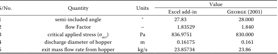
Table 4. Conical hopper design parameters
S/No. Quantity Units Excel add-in Value George (2001)
1 semi-included angle ° 27.83 28.000
2 flow Factor – 1.83529 1.840
3 critical applied stress (σacr) Pa 836.9751 830.000
4 discharge diameter of hopper m 0.16175 0.161
[image:4.595.66.533.668.759.2]are used to obtain the critical applied stress. The data for the wall friction in Table 3 are curve fit-ted, and the slope of the resulting curve is used to determine the angle of wall friction (δw) where tandw =dv du/ ≈ ∆ ∆v u/ ; and the data for the ef-fective angle of internal friction are similarly used to determine the effective angle of internal friction (δ) where tand =dy dx/ ≈ ∆ ∆y x/ .
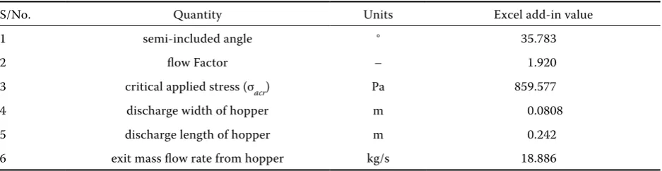
The design parameters for the conical hopper that the MS Excel add-in produced are tabulated in Table 4 along with those obtained by George (2001), using the same input data. It is seen that the largest percentage relative error of 0.84% occurred in the computed value for the critical applied stress (σacr ). This, granted that the results by George (2001) are error free, may be attributed to roundoff errors in the computational process. But this error is quite acceptable for hopper applications. Table 5 shows the design parameters for the wedge hopper based on the same input data used for the conical hopper. Here, direct comparison cannot be made as George (2001) did not consider the wedge hop-per. However, one observes that all the parameters increased except the equivalent discharge diameter (de = 0.121 m) and the mass flow rate of the wedge hopper, which are less than those of the conical hopper. Therefore, the results obtained confirm that the replacement of the Jenike’s chart by alge-braic correlations aids in computerizing the hopper design process, which is the trend in contemporary engineering practice.
COnCluSIOn
This work has eliminated the manual application of the Jenike’s hopper design charts for mass flow as well as the graphical determination of the critical applied stress. Algebraic polynomial correlations
have been generated to replace the Jenike’s hopper design charts, and a numerical scheme is used to determine the critical applied stress. A spreadsheet add-in tool in MS Excel environment has been de-veloped for the automatic design of the conical and wedge hoppers based on the Jenike’s hopper design scheme. Apart from the stand-alone application of this spreadsheet add-in tool, it can also be integrat-ed into a larger plant design software for improvintegrat-ed productivity. Of course, the add-in is also a veri-table tool for the effective teaching of engineering students how to design hoppers.
references
Bridgwater B.N., Scott H.C., 1983. Static and dynamic silo loads using FEMs. Journal of Agricultural Engineer-ing, 3: 299–308.
Chapra S.C., Canale R.P., 2002. Numerical Methods for Engineers. 4th Ed. New Delhi, Tata McGraw-Hill.
Fitzpatrick J.J., Barringer S.A., Iqbal T., 2004. Flow property measurement of food powders and sensitivity of Jenike’s hopper design methodology to the measured values. Journal of Food Engineering, 61: 399–405. George G.C., 2001. Solids flowability. University of Akron.
Available at: www.ecgf.uakron.edu/chem/fclty/chase/sol-idsNote.PDF (accessed August 2007)
Griffith M.S., 1991. Cake formation in particulate systems. New York, VCH Publishers.
Holdich R., 2002. Fundamentals of particle technology. Loughborough, Midland Information Technology and Publishing.
Hsiau S.S., Smid J., Tsai F.H., Kuo J.T., Chou C.S., 2001. Velocities in moving bed filter. Powder Technology, 114: 205–212.
Jenike A.W., 1994. Storage and flow of solids. Bulletin No. 123, Engineering Experiment Station, University of Utah. Jenike A.W., Johanson J.R., 1969. Bin loads. Journal of
[image:5.595.64.533.101.222.2]Structural Division (ASCE), 94(ST4): 1011–1041. Table 5. Wedge hopper design parameters
S/No. Quantity Units Excel add-in value
1 semi-included angle ° 35.783
2 flow Factor – 1.920
3 critical applied stress (σacr) Pa 859.577
4 discharge width of hopper m 0.0808
5 discharge length of hopper m 0.242
6 exit mass flow rate from hopper kg/s 18.886
Johanson J.R., 1966. The use of flow-corrective inserts in bin. Transactions of the ASME Journal of Engineering for Industry. 88: 224–230.
Johanson J.R., Kleysteuber W.K., 1969. Flow corrective in-serts in bins. Chemical Engineering Progress. 11: 79–83. Knowlton T.M., 1994. The importance of storage, transfer
and collection. Chemical Engineering Progress, 90: 44–54. Liengme B.V., 2000. A guide to Microsoft Excel for scientist
and engineers. London, Butterworth-Heinemann. Mustafa G., 2000. Correlations for some thermophysical
properties of air. Wageningen, NL, International Drying Symposium.
Oko C.O.C., 2008. Engineering computational methods: an algorithmic approach. Port Harcourt, University of Port Harcourt Press.
Peleg M., 1978. Flow ability of food powders and methods for its evaluation – A review. Journal of Food Process Engineering, 1: 303–328.
Rhodes M., 1990. Principles of powder technology. New York, John Wiley.
Stasiak M., Molenda M., 2004. Direct shear testing of flowability of food powders. Research in Agriculture En-gineering, 1: 6–10.
Received for publication August 19, 2009 Accepted after corrections September 14, 2009
Corresponding author:
Oko C.O.C., Ph.D., University of Port Harcourt, Faculty of Engineering, Department of Mechanical Engineering, PMB 5323 Port Harcourt, Nigeria